

Page 1
www.docherty.co.uk
SEVERN FIREPLACE INSERT
INSTALLATION MANUAL
SINCE 1960
Page 2

1. Introduction
Thank you for purchasing one of our replace stoves and congratulations on becoming the
owners of a prestigious quality appliance by Docherty.
Our replace stoves can function as additional heating to augment the atmosphere of your
home or recreational building or as the main source of environmentally-friendly heating with
high heat output, clean operation and perfect combustion. All replace heaters produced by
our company are tested in accordance with EN 13240/2002+A2/2005 or EN 13229/2002.
Please read through the manual and technical sheet thoroughly. The user is obliged to get
properly acquainted with proper installation and operation of this device with regards to its
safe operation. Please retain the manual and technical sheet as a reference guide so that you
can brush up all the information necessary for the correct operation of your replace stove
before each heating season.
We only provide a warranty on our products if all the instructions listed in this operation
manual are adhered to.
2. Technical description
Fireplace inserts are intended for building into stoves in various interiors (apartments,
recreation buildings, restaurants). Romotop replace inserts are manufactured from quality
construction materials – cast metal,
CORTEN steel and quality construction and ttings steel, with stressed parts made of
HARDOX steel. The surface of steel constructions is protected by a refractory opaque paint.
Refractory paints are not anti-corrosive.
The combustion chamber of full-plate replace inserts is padded by removable chamotte re
bricks, which are not connected by any paste material to prevent damage by heat dilatation.
The combustion chamber can be rmly closed by doors with special heat-resistant glass. The
glass not only increases the aesthetics of the ickering ames, but also facilitates pleasant
heat radiation. The glass also prevents the sparks from the burning wood and smoke from
entering the room. The oor of the combustion chamber is usually equipped with a
removable cast iron grate. Usually, a barrier, or alternatively a sheet metal or ceramic mould,
is placed in front of the grate to prevent the fuel falling and sliding onto the doors (front
window). Stoves with a grate include room for an ashpan under the grate. Some types allow
custom-conguration of the ue pipe throat for top- or back-side exhaustion.
Some types of replace inserts have a rotary exhaust ue pipe throat. The replace insert
design may include a single coating or be supplemented with an external coat of zinc-coated
sheet metal with outlets for connection to the heat system. Installation of a support fan is
recommended for vertical heat pipes longer than 4m.
Fireplace inserts equipped with a separate intake of primary and secondary combustion air
include the appropriate control elements. The primary air is taken to the burning fuel
(usually through the ashpan and grate) and is used for primary combustion. The secondary
air supports combustion of residual combustible gases in the exhaust, increasing the output
of the heater and signicantly reduces the amount of pollutants escaping into the atmosphere.
The secondary air is mostly taken to the area above the burning fuel. Its presence causes the
cold air to roll around the inner side of the front glass.
General installation and operation manual for Romotop replace inserts
- valid in general for all types of Docherty replace inserts
The attached technical sheet lists detailed technical data for each type of replace insert.
The replace inserts may only be operated in accordance with this manual!
No unauthorized changes may be performed on the replace inserts!
Page 3

This process simultaneously prevents the blackening of the front glass. The secondary air
also participates in the primary combustion process when the primary air intake is partially
or completely sealed. Keep the primary air intake fully open at the beginning of the combustion
process, when the chimney draft is still weak.
After the chimney heats up, you can partially or even completely close the primary air intake,
based on the target output of the replace insert. It is also possible to reduce the fueling
or limit the chimney draft by attaching a smoke shutter (a manual shutter in the ue pipe
limiting the air intake to at most 75%) to reduce the output of the replace insert. This is
recommended especially for chimney draft around and above 20Pa.
The secondary damper is intended to fully close the stove when it is not in operation. The
replace and ashpan covers must always be closed except for starting operation, adding fuel
and removing solid combustion remnants to prevent exhausts entering the room.
Some replace inserts are manufactured with a central air intake (CAI). This allows air to ow
into the combustion chamber in the replace insert from the exterior, halls, technical rooms
etc. Fireplace inserts with a CAI are not dependant on the amount of air in the heated area.
Thus, they not only contribute to a pleasant atmosphere in your home, but also reduce
energy expenses (since heated air already in the room is not consumed).
Fireplace inserts with a CAI are very convenient for stoves in low-energy houses. It is also
possible to equip the heating system of some replace inserts with CAI with electronic
combustion regulation to increase comfort. This can additionally increase the combustion
process and stoking intervals, increase operation safety and prevent uneconomic heating
and over-heating of replace inserts (the shutter of the central air intake is controlled by a
control unit and servomotor in relation to the current combustion phase and output exhaust
temperature).
In all cases when using the direct air connection the installer is required to install and
commission the appliance inline with current Building Regulations, manufacturer’s instructions
and any commissioning guidelines for a direct air kit, (example: the HETAS Direct Air Supply
guidelines TN010, TN011, TN012. Details are also going to be included in the next revised
standard of BS 8303). Details are available on request.
Warning: The replace inserts are not manufactured to provide continual heating and are
intended for periodic interrupted operation, mostly due to the need to empty the ashpan
when the ash has cooled down.
3. Safety regulations
Special care must be taken when installing the stove such that the requirements of the
Health and Safety at Work Act are met.
A supply of sucient amount of combustion air and room ventilation air must be ensured
when the replace stoves are in operation, especially with another heat device running
simultaneously. The regulation grate for combustion, ventilation and heating air must not be
obstructed.
When stoking fuel, always open the door very slowly. You will prevent smoke and ash from
escaping into the room. The replace stoves require casual attendance and inspection.
Flammable fuels must not be used for stoking or heating! In addition, burning plastic material
of any kind, wood materials with various chemical bonding agents (chipboards, etc) or
unsorted domestic waste with remaining plastics is prohibited.
Make sure to prevent children from handling the replace stoves during heating. The stove
may only be operated by an adult person! A reguard to BS 8423:2010 should be tted in the
presence of children, aged and/or inrm persons.
Page 4
During heating all handles and knobs must be operated using a pair of tongs, hook or by a
hand protected by a glove due to the risk of burns. Objects made from ammable materials
that could be set on re must not be stored on the replace stoves during operation and
while hot.
Please pay special attention when handling the ashpan and when removing hot ash due
to danger of burns! The hot ash must not get in contact with ammable objects -e.g. when
throwing in communal waste containers.
When the replace stove is used only seasonally and with unfavourable draught or weather
conditions, special attention must be paid when putting the stove into operation. When the
replace stove is not in operation for a longer period of time, the ueways must be checked
for obstructions before further operation.
Handling
Adequate facilities must be available for loading, unloading and site handling. This appliance
is heavy and must be handled with care.
Fire Cement
Some types of re cement are caustic and should not be allowed to come into contact with
the skin. In case of contact wash immediately with plenty of water.
Asbestos
This stove contains no asbestos. If there is a possibility of disturbing any asbestos in the
course of installation then please seek specialist guidance and use appropriate protective
equipment.
Metal Parts
When installing or servicing this stove care should be taken to avoid the possibility of personal
injury.
3.1 Safe distance:
3.1.1 Safe distance of replace inserts from ammable materials
400mm to sides
400mm to rear
800mm in front of the centre point of door assembly
Note:These distances double if material is easily ammable example, breboards,
polystyrene, polyurethane
Any storage area built into the appliance must not be used to store any combustible materials.
The installation must comply with current Building Regulations, National and European
Standards, Local Authority byelaws and other specications or regulations as they aect the
installation of the stove. The most stringent clearances to combustibles should be applied.
3.1.2 Safe distance of chimneys from ammable materials and building constructions
When constructing an enclosure (such as Silca 250) to protect the structure and fabric of the
building. It should be used to protect any adjacent walls and ceilings where re protection
is required please follow manufacturers installation instructions for protective board being
used.
It is also important that the correct levels of ventilation are installed as to ensure that no
surfaces of the installation or adjacent surfaces (including walls and ceilings) reaching a
temperature above 85 deg C.
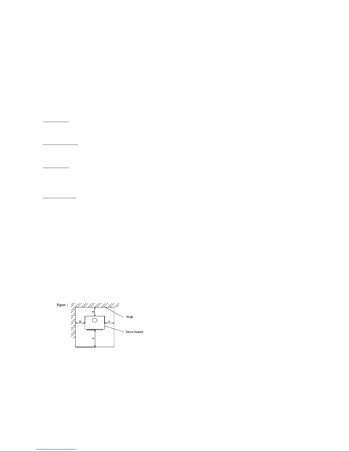
Minimal distances:
A = 80cm
B = 40cm
Page 5

3.2 Floor protection
Unless the replace is installed on a 100% non-ammable oor it will be necessary to stand
the appliance on a non-combustible base of at least 12mm thick and able to withstand the
weight of the appliance and nished construction. It should extend 800mm in front of the
appliance and 400mm to sides and rear of the appliance. However if the oor area is larger
than this it would be good practice to cover the entire internal oor area of the enclosure.
The surface temperature of the nished oor should not exceed 85 deg. C when in normal
operation, otherwise a constructional hearth of 125mm thick will be required. There is a risk
of increased temperatures if correct levels of ventilation are not achieved.
3.3 Chimney re prevention measures:
Ordinary operation, especially with humid fuel, leads to the settling of ash and tar in the
chimney. Neglecting regular checking and cleaning of the chimney in accordance with Building
Regulations increases the danger of re. We recommend that the chimney should be swept
twice a year.
In case of ash or tar catching re in the chimney, please follow this procedure:
• do not under any circumstances extinguish the re with water as it would create an
abnormal amount of steam and subsequently rip the chimney open
• if possible, the combustion chamber should be covered with dry sand, which will extinguish
the re
• close all intakes of air for combustion; if possible, cover the chimney. However, the smoke
must not accumulate back in the house
• contact your nearest re ghting brigade to assess the situation and the necessity to
report it as a re ghting emergency
• do not leave the house until the chimney is burned up; regularly check the chimney
temperature and the course of combustion
• contact a chimney service engineer before starting a new re in the stove to assess the
state of the chimney and also contact the manufacturer of the replace stove for inspection.
4. Assembly regulations
4.1 General
The replace insert must be installed on the appropriate stand supplied by the manufacturer
or on a brick pedestal on oors with an appropriate load capacity. In case of replace inserts
with an enclosure, it is necessary to also consider the weight of the enclosure! If the existing
arrangement does not meet this basic requirement, necessary steps must be taken (e.g.
using a oor plinth/hearh for distributing the load). Make sure that there is enough space for
cleaning the replace insert, connecting ue pipes and the chimney unless the chimney can
be cleaned from other method, e.g. cleaning access door designed for this purpose.
4.2 Chimney connection
Before assembling the closed replace insert it is necessary to calculate that the chimney
construction will be suitable for the installed replace insert nominal output as far as design,
vent size and eective height are concerned.
A suitable chimney (minimum prole, chimney draft, tightness, etc.) is a basic condition for
the proper functioning of the replace inserts. You should therefore contact an approved
installer before installing the replace insert. Chimney values are included in the attached
technical sheet. A smoke shutter or a draft regulator should be installed for chimneys with
too strong a draft. Such a draft can cause problems during operation, e.g. intensive burning,
high fuel consumption and can also lead to permanent damage of the replace insert.
The minimum eective height of the chimney for exhaust gas from the insert is 5m.
Page 6

4.3 Enclosure of replace inserts
Special expertise is required for building the replace insert into the replace.
The installation must comply with current Building Regulations, National and European
Standards and any Local Authority byelaws.
2. After installing the whole replace, the inlet and outlet of conventional air through any
construction parts must not be limited. The cross section of the inlet and outlet of air grilles is
listed in the technical sheet.
3. To augment the nal appearance of the replace, the dimensions of the door frames
exactly match the ceramic facing produced by Romotop spol. s.r.o.
4. The enclosure must be made of suitable, designated materials.
5. The warm conventional air outlet must be at least 30cm below the ceiling (gure 2).
6. An inammable ceiling construction must be present above the conventional warm air
outlet. Its temperature must not exceed 85deg C. Thus, the lower ceiling must be insulated
from the eects of heat coming from the replace by a barrier and at least one not fully
closeable grated opening (gure 2)
7. The same requirements also hold for the walls next to the replace and for the oor. A
ventilated air space must remain between the heat insulation and the wall.
8. The wall of the replace must not contain electric wiring and water or gas distribution
pipes. The wall nor its surface may contain ammable materials or materials which may
release harmful substances when heated.
9. Minimal free distances must be kept between the replace insert and the cover (see
technical sheet) for the whole height and width of the replace insert, so that convected air
can freely circulate and prevent the overheating of the replace set.
10. Eventual air conditioning piping must be located at least 40 cm from ammable building
constructions, or it must be documented that the heat from the piping cannot cause the
construction to catch on re. Convected air can reach temperatures of up to 300°C near the
insert!
11. Do not forget that replace inserts also spread heat in the direction of the oor. The oor
under the replace and at a distance of at least 80cm in front of the furnace and 40cm to the
sides of the furnace must be made of an inammable material. The distance is measured
from the closer edge of the furnace. The surface for the replace must have an appropriate
load capacity.
12. Do not forget that when considering the use of wooden decorative ledges, these must be
made of quality wood with a humidity of at most 15% and that convected cooling air must
ow around it with a gap of at least 1cm or they must be heat-insulated from the replace, so
that their surface temperature does not exceed 85 deg C.
13. When distributing hot air via natural air circulation, it is recommended to use horizontal
pipes at most 4m long. When distributing hot air via forced air circulation, the length of pipes
is not limited.
14. The pipes for distributing hot air must be tight and made of a material resistant to
operating temperatures. We recommend insulating them at the whole length, especially
where they traverse walls, ceilings or around ammable materials.
15. Hot air outlets must not be located at areas with materials susceptible to structural
changes caused by temperature uctuations (e.g. polyester lining, certain types of wallpapers
etc.)
16. No construction changes or adjustments may be performed on the replace insert!!!
01 – chimney vent
02 – wall
03 – insulation area above the chamber
04 – hot air chamber ceiling
05 – ventilated air gap
Vertical cross section of single-coating replace with closable furnace
06 – heat insulating layer
07 – hot air chamber area
08 – replace insert ue pipe
09 – replace insert smoke chamber
10 – closed replace furnace
Page 7
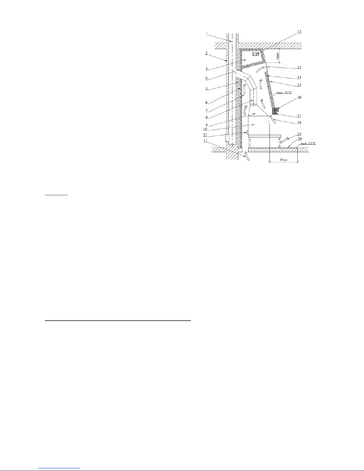
Figure 2
A chart of the replace set holds in general also
for double-coating replace inserts and replace
inserts with a heat-accumulating and warm water
exchanger
11 – air intake from other rooms (or CAI)
12 – ventilation of ceiling insulation areas 13 –
hot air outlet from the chamber
14 – heat insulating layer
15 - wall of hot air chamber
16 – replace ledge
17 – replace ledge protection
18 – air intake for hot air chamber
19 – air intake from the room to under the
replace insert
20 – inammable oor (pad) in front of the
replace
21 – CAI throat
5. Operation manual
5.1 Fuel
It is only allowed to burn wood and wood briquettes in replace inserts. To reach the
nominal parameters of the heater, we recommend using dry logs with a diameter of 5-8 cm
and length of 20-30 cm and with a humidity below 20% (ideally 10%), or compressed wood
briquettes. Oven wood and chopped pieces of wood should be used only when starting the
re. Recommended humidity can be obtained by storing the chopped logs for at least two
years in a ventilated shelter. Wood briquettes must be stored in a dry place, otherwise they
might fall apart.
The replace insert should be heated to a nominal output stated in the technical sheet, i.e.
the burning of a given amount of allowed fuel per 1 hour. Long-term excessive output could
damage the replace stove.
Never use ammable uids, coke, coal or any of the following types of waste as fuel:
chipboards, plastics, plastic bags, soaked wood or wood-shavings, saw-dust or pellets!
!!!Burning of the abovementioned material not only highly pollutes our environment but also
damages the replace insert and the chimney!!!
5.2 Starting the replace insert for the rst time
Before the rst use all remaining stickers must be removed, all accessories must be taken
out of the ashpan or replace and the same applies for the transport safety pins. Check
that bulk shutters for directing the draft, chamotte tiles and the barrier are set correctly
(as they might have slipped from their correct positions during transport or installation).
Repair any defects you might nd in setting, otherwise the proper functioning of the heater
is endangered. After setting the replace insert, connecting it to the chimney and, if need be,
connecting the
exchanger to the warm-water set and lling it with a heat-carrying medium, start heating
slowly and continue for at least one hour. Leave the stoves and ashpan doors open (approx
1-2mm) before and during the rst heating in order to prevent the sealing material to mix
with the paint. The replace insert surface is covered with heat-resistant paint. During the
rst heating, after becoming temporarily soft, the paint will eventually become hardened.
During the soft phase the paint surface is more vulnerable to being damaged by a hand or
other object. During the rst heating the replace insert should be “heated up” with a small
ame, burning only a small amount of fuel with a lower temperature. All materials must get
used to the heat load.
Page 8

You will prevent cracks in chamotte bricks, damage of the paint or deformation of the insert
materials by a careful rst heating.
Hardening of the paint on the replace insert might be accompanied by a temporary smell,
which will disappear after a while.
Make sure the room is properly aired when burning the paint. Furthermore, ensure that no
small animals or birds are present in the room containing paint exhausts.
We also recommend turning o aquariums air intakes during the rst heating.
In general, the heating up and cooling of the replace insert is accompanied by a specic
sound; this is intended.
After the replace insert and eventually the exchanger cools down, it is possible to begin
assembling the outer coating of the insert.
5.3 Kindling and ring
1. Fireplace inserts with grate - rst put crumpled paper into the chamber and then lay
chopped wood on it.
You can also used the solid re-lighter to start the re. After starting re, let it burn freely
with all air regulation elements open. It is forbidden to use ammable liquid (oil, petroleum,
etc.) for starting re!
After the re begins to burn and the draft is strong enough, bigger logs or wood briquettes
might be added without the danger of smoke. Continue stoking the amount of fuel determined based on the nominal output of the replace insert.
2. Fireplace inserts without grate - only secondary air is used for burning; therefore wood
logs need to be stoked rst, then chopped wood and nally small cuttings and paper. After
starting re, let it burn freely with all air regulation elements open. It is forbidden to use
ammable liquid (oil, petroleum, etc.) for starting re!
After the re begins to burn and the draft is strong enough, bigger logs or wood briquettes
might be added without the danger of smoke. Continue stoking the maximum amount of fuel
determined based on the nominal output of the replace insert.
Fuel consumption is always stated in the technical sheet. Burning intensity is regulated by air
intake controls or, if a smoke shutter is installed, by limiting the draft in the chimney. Larger
amount of fuel or a strong draft and air take might cause overheating and damage of the
replace insert. Too weak draft leads to glass blackening or to a smoke escaping into the
room when opening the door and stoking fuel.
Warning: Fireplace doors must always be closed, with the exception of the rst heating,
stoking fuel and removing ash. When the replace insert is not in operation for a longer
period of time, it is necessary to check that the ue pipes, chimney and combustion chamber
are clear.
5.4 Stoking fuel
In order to prevent smoke escaping into the room when stoking fuel, please follow the following procedure:
Approximately 5 or 10 seconds before opening the replace doors open the air intake regulators and then only slightly open the stoking doors, wait for few seconds for the exhaust
gas to get sucked into the chimney and only then fully open the door. When opening the
stoking door, a special attention must be paid to the danger of hot re-brands falling out.
After stocking fuel, close the door again. After the fuel starts burning (with clear re), return
the regulator back to its original position. The amount of stoked fuel should correspond to an
hourly consumption value for the concrete replace insert (see the technical sheet).
Overheating can permanently damage the replace insert construction.
Warning: To prevent exhaust gas escaping into the room during stoking add fuel after its
burning down on the glowing base.
Page 9

5.5 Operation during the transition period
The chimney draught (sucking exhaust gas from the replace insert) might be weaker during
the transition period, i.e. when the outside temperature is higher than 15°C, during rainy and
humid days or during gust airs.
During this period the replace insert should be operated with the minimum possible fuel so
that the re, as well as the chimney draft could be improved by opening the air intakes.
Tip: During this period a so-called atmospheric plug can be created in the chimney mouth
due to the draft conditions. The plug can caused smoke escaping into the room when lighting
fuel. We recommend letting a piece of paper burn down preferably in the upper part of the
combustion chamber before lighting the kindling.
This seemingly negligible smoke is enough to break through the atmospheric plug.
Afterwards you can freely light paper (or solid re-lighter) and be sure that even a humid
chimney is clear.
In this period it is also possible to use the same lighting method as for the replace inserts
without grate (with no ashpan).
5.6 Ash removal
Make sure that the ashpan is cleaned when being half full in order to prevent the ash reaching
too close to the grate and thus damaging it. At the same time the ash would block the intake
of air required for burning.
Removing ash from the ashpan should be carried out when the replace stove is cold and
preferably ready for the next heating. A vacuum cleaner designed for cleaning ash with a
lter for small lth can be also used for cleaning the cold ashpans or heater without ashpans. Ash
from burnt wood can be used for composts or fertilizing. Store the ash in closed non-ammable
containers.
Warning: Make sure that the ash does not contain any glowing remains of wood that could
cause re in the waste container.
Warning: For some replace insert types the ashpan is located in a basin under the grate
and cannot be removed from the side. The ashpan can be removed only when the heater is
cold and not in operation. The ashpan is accessible after lifting the grate.
Be careful when removing hot ash!
5.7 Cleaning the glass
The cleanliness of the window is inuenced not only by the using of suitable fuel, providing
sucient air intake and chimney draft but also by the method of operating the replace
insert. In this respect we recommend stoking only one layer of fuel and distributing the fuel
as evenly as possible and as far from the glass as possible. This also applies for briquettes
(the distance between them should be 5 to 10 mm). If the glass becomes dirty, try increasing
the burning intensity by opening the air intake and the glass will clean itself.
Sooty windows can be cleaned in cold state using newspapers or wet cloth dipped in wood
ash. Usually also liquid cleaning agents are used for cleaning the stove window. But these
may in some cases, depending on the composition of the cleaning agent and its interaction
with combustion residues (ash particles, etc.), harm the gaskets and/or the glass-ceramics
and/or the decoration colour of the replace viewing panel.
The producer is not responsible for damages, which are caused by attack in using of chemical
agents.
6. Cleaning and maintenance
Your replace insert is a high-quality product and no signicant defects will appear during
normal operation. The replace insert and exhaust pipes should be checked thoroughly
before and after the heating season. Clean the replace insert only after it cools o!
Page 10

6.1 Cleaning the replace inserts / disassembly of chamotte
All sediments in ue pipes and combustion space must be removed during cleaning. Repair,
ideally by removing, all fallen-o parts of the chamotte lining. The integrity of the chamotte
lining must be monitored also during the heating season. Spaces between individual chamotte
ttings serve as a heat dilatation preventing cracking of the ttings and must not be lled by
lling material as was usual with older types of solid fuel heaters. Cracked chamotte ttings
are still functional until they fall out! If a ue damper/shutter for directing the draught, if
used, should be removed during cleaning (this enables easier access to the space above
them). The replace insert cleaning (with the exception of glass) should be done without
water cleaner, i.e. using only vacuum cleaner or brushes. Any modications of the replace
insert are unacceptable. Use only spare parts approved by the manufacturer. Disassembly
of chamotte (see the Chamotte chamber). From time to time the friction areas of the door
hinge and the closing mechanism should be oiled using carbonic fat or grease designed for
high temperatures. Close the replace insert with corresponding slide controls when not in
operation.
6.2 Cleaning the chimney
Each user of a solid fuel heater is obliged to ensure regular maintenance and cleaning of
the chimney in accordance with Building Regulations. The frequency may alter with use but
we recommend a minimum of twice a year when burning wood with the correct moisture
content.
7. Warranty
Packaging and the discarded product should be liquidated in accordance with local byelaws.
Brand-new wood-burning stoves from Docherty Group come with a 5-year warranty. The
warranty includes manufacturing or material defects and burn-through of the main body as a
result of correct operation.
Any claims during the warranty period should be directed to the dealer who sold the stove.
All stoves from Docherty Group come with their own individual serial number this can be
found on the data plate axed to the appliance. This may be located either on the back of
the stove or within the storage area beneath the stove. Please quote stove model and serial
number to your dealer in connection with any service enquiries.
In the event of warranty repairs, a signed and dated invoice must also be produced, showing
the dealer’s name.
The warranty does not cover dismantling, transport and reassembly of your stove.
No compensation will be granted for:
• Damage during transport
• Damage to other articles resulting from use of the stove
• Damage arising from incorrect operation or use, such as overheating – avoid this by
reading the operating instructions carefully
• The directions in the operating instructions have not been followed
The stove is supplied with wearing parts (also referred to as perishable or moveable parts),
which are to be replaced due to usage of the stove.
These parts are not covered by the warranty – how often they are to be replaced is individual
and depends on the stove usage. These components include (but not limited to) the following:
Vermiculite panels or chamotte (if tted) - bae plates – all seals – operational handles.
Other items not covered by the warranty include glass, ceramic tiles and soapstone. Should
any of the above mentioned need replacing, new parts can be ordered from your dealer.
Grate (if tted), electronic components (if tted) and manual air controls carry a 24 month
warranty.
Page 11

The stove installation must be signed o (certied) by a registered installer, Building Control
Body or local authority to validate the manufacturer’s warranty. The warranty is null and void
if this is not adhered to.
Regular maintenance of the stove and annual servicing and the need to have the chimney
swept at least once a year to prevent overheating and premature failure of components.
Proof of which must be available at any time of a warranty claim. Please see section 6 for
further details on cleaning and maintenance.
Regular maintenance, annual servicing and the requirements under Building Regulations to
have the chimney swept at least once a year (we recommend twice a year) to prevent
overheating and premature failure of components. Proof of which must be available at any
time of a warranty claim.
Warranty claims are only accepted and processed for the purchaser.
When transferring items for warranty, the purchaser is obliged to inform and eventually
document the type label of the product and a detailed description of the defect (e.g. in which
mode and how the defect manifests, how long after combustion, description of operation of
the item before the defect etc).
Page 12
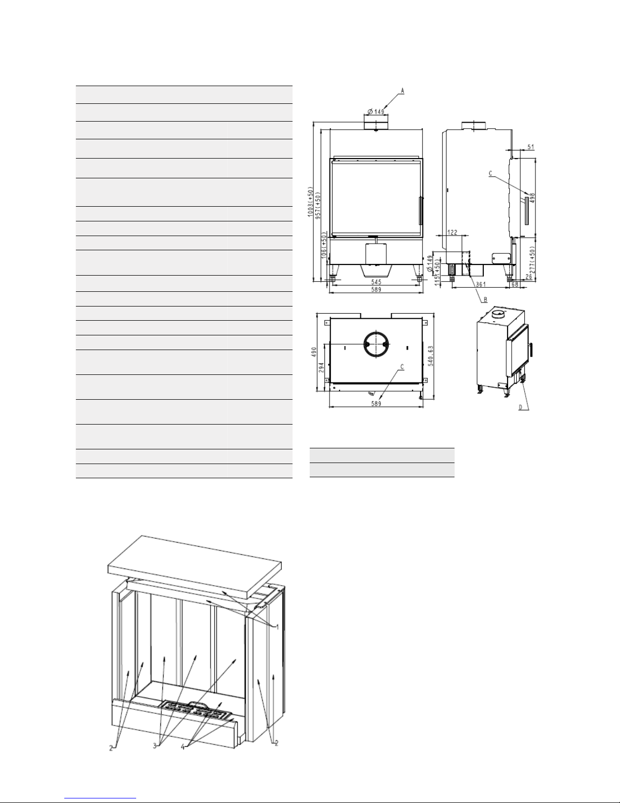
8. Technical information
Nominal output 7 kW
Regulated output 3.5 - 10 kW
Eciency 85%
Weight 150 kg
Flue outlet 150 mm
Dimensions (mm)
1003x589x
490
Average wood consumption (kg/h) 1.9
Max. allowed wood batch (kg/h) 2.5
The greatest height of the lling 1/3 of rebox
Fuel supply interval for the rated
output
1 hour
Fuel delivery method Manual
Prescribed fuel Wood
Door with spring return Yes
Door design Left
Chimney draft (Pa) 12
Mass ow rate of dry ue gases
(g/s)
4.9
The concentration of CO in the ue
gases at O2 = 13%
0.089
The concentration of CO in the ue
gases at O2 = 13% (mg/Nm3)
1117
The concentration of CO in the ue
gases at O2 = 0% (mg/MJ)
753
Dust at O2 = 13% (mg/Nm3) 13
Average ue gas temperature (°C) 218
Approvals
EN 13240/2002+A2/2005
3
DIN plus
3
EN – Procedure for exchange of chamottes:
1. Pull out the ceiling reclay plat – 1
2. Pull out the side reclay plates - 2
3. Pull out the bottom reclay plates - 4
4. Pull out the rear reclay plates - 3
5. Use the reverse order for re-assembly
Note: Cracks in the chamotte do not have
any eect on the combustion and service
life of the stove. The chamottes should not
remain crumbled to the metal for prolonged
periods of time.
Warning: When stoking logs, make sure they
do not hit the chamottes hard to prevent
damage!
Page 13
www.docherty.co.uk
Docherty Group
55 Woodburn Road, Birmingham, B66 2PU
Tel: 0121 555 6789
Email: [email protected]
Warranty registration form
Name and address of installation:
Date of installation:
Name and address of installer:
HETAS registration number:
Signed: Date:
Severn Tweed
Please return to Docherty Group 55 Woodburn Road, Birmingham, B66 2PU
DerwentInsert brand:
Alternatively, you can ll out the form below and post it back to Docherty Group
It’s quick and easy to register your Docherty stove online.
Simply visit our website at www.docherty.co.uk and complete
the warranty registration form
www.docherty.co.uk/stove-warranty-registration
WARRANTY REGISTRATION
SINCE 1960
 Loading...