

Page 1

WokerWoker--Attandance Device of Construction SiteAttandance Device of Construction Site
RFID&BiometricsRFID&Biometrics
SystemSystem
RFID&BiometricsRFID&Biometrics
SystemSystem
GatewareGateware--FVSFVS
ver. ver. –– 1.01.0
User ManualUser Manual
Page 2

GATEWARE-EM
Doalltech
C
o
n
t
e
n
t
s
Contents
User Manual
l Matters that require attention
l Product Explanation
1. Starting
l 1. Check of the supply items
l 2. Installation method
l 3. Each part Name & Function of the Device
2. System setting
l Explanation of the Screen UI
l Explanation of the keypad control
----------------- 3
----------------- 6
----------------- 7
----------------- 8
---- 9
---------------- 11
---------------- 12
2
User Manual
l Matters that require attention
l Product Explanation
1. Starting
l 1. Check of the supply items
l 2. Installation method
l 3. Each part Name & Function of the Device
2. System setting
l Explanation of the Screen UI
l Explanation of the keypad control
l Menu Control - Enter
l Menu Control – Select the item
l Menu Control – Check the status
l Menu Control – Default setting
l Menu Control – Serial pot setting
l Menu Control – Relay setting
l Menu Control – Special setting
l LAN Setting
l USB setting
l Time setting
l Password setting
3. Reference
l External Interlocking device – Turn-Gate
l External Interlocking device – Items
l Additional Function
l FAQ
l Before A/S Request
l Product Size
l FCC RF INTERFERENCE STATEMENT
l Additional charge item
English
----------------- 3
----------------- 6
----------------- 7
----------------- 8
---- 9
---------------- 11
---------------- 12
---------------- 15
---------------- 16
---------------- 17
---------------- 18
---------------- 19
---------------- 20
---------------- 21
---------------- 22
---------------- 23
---------------- 24
---------------- 25
--------- 26
-------------- 27
---------------- 28
---------------- 30
---------------- 32
---------------- 38
-------------- 39
Page 3

GATEWARE-EM
Doalltech
Matters that require attention– Sign explanation, Power supply
W
a
r
n
I
n
g
&
C
a
u
t
ØSign explanation
v Please read this manual and keep the using method because for prot
ecting risks or damages on property by using the product correctly.
l This is composed of contents on the possibility of death or
serious wound in case of violating instructions.
l If violate the instruction, you are vulnerable to wounds or
occurrence of property loss.
caution
warning
3
W
a
r
n
I
n
g
&
C
a
u
t
I
o
n
English
Theses images are just for reference. It can be different from real product appearance
Ø Please plug into correct place
§ In case of unstable situation, it causes fire or
electronic shock
Ø Don’t touch the Power supply with wet hand
§ It causes fire or electronic shock
Ø Power supply
warning
Reference
Page 4

GATEWARE-EM
Doalltech
W
a
r
n
I
n
g
&
C
a
u
t
Matters that require attention
Ø Please don’t use a damaged plug or loose outlet
§ It causes fire & electronic shock
Ø Please do not use a lot of plugs into one outlet.
§ It causes a fire owing to abnormal heat of the
warning
W
a
r
n
I
n
g
&
C
a
u
t
I
o
n
English
Theses images are just for reference. It can be different from real product appearance
Ø Don’t press the power line with heavy things
and bend forcibly or pull it.
§ It causes fire & electronic shock
Ø When moving the product, please turn down
the switch certainly and then move it after taking
out external cable.
§ It causes fire & electronic shock
Ø Please do not use a lot of plugs into one outlet.
§ It causes a fire owing to abnormal heat of the
outlet.
4
Reference
Page 5

GATEWARE-EM
Doalltech
Matters that require attention
W
a
r
n
I
n
g
&
C
a
u
t
Ø Don’t make DC Power supply (Adapter) device
wet & keep away from water
§ It causes fire & electronic shock
Ø Don’t put the Power supply device or Power
supply wire around heater.
§ It causes fire
caution
5
W
a
r
n
I
n
g
&
C
a
u
t
I
o
n
English
Theses images are just for reference. It can be different from real product appearance
Ø When you pull out Power supply plug, please
use only plug which is not wire. It causes wire
problem
§ it causes power switch problem or fire
Ø when Thunderstorm or lightening situation,
please pull out the power supply plug
§ It causes electric shock and fire appliances’ a
bnormality.
Reference
Page 6

GATEWARE-EM
Doalltech
S
t
a
r
t
Product summary
1. Summary
l The entry control management using
RFID card & Finger Vein Pattern.
l Real-time confirmation on the entry situation
l It stores output data of workers and has transmi
tting function to remote- place server by using
network
6
• Product appearance& specification can be changed for high quality improvement
1. Summary
l The entry control management using
RFID card & Finger Vein Pattern.
l Real-time confirmation on the entry situation
l It stores output data of workers and has transmi
tting function to remote- place server by using
network
2. Feature
l Photographing, external camera input, image ou
tput, external RFID device input, external RS-232
device input, sensor input and relay output are
available by connecting with various external de
vices.
3. Interlockable External device
l CCTV Camera, TV Monitor
l Turnstile Gate, Automatic door
l Crossing barrier,Eletric sign,Flash light and so on
l 13.56Mhz RFID Reader, Finger Vein Reader
English
Reference
Page 7

GATEWARE-EM
Doalltech
A
d
v
.
p
r
e
p
a
r
a
t
I
1. Composition item check
Gateware FVS Main body Main body holder
A
d
v
.
p
r
e
p
a
r
a
t
I
o
n
s
7
• Picture size of each item can be different from real product size,, Some part items
can be changed depending on the situation.
Gateware FVS Main body Main body holder
Main body Adapter Main body Key
SD Memory USB Memory User Description
English
Reference
Page 8

GATEWARE-EM
Doalltech
2. Installation method
A
d
v
.
p
r
e
p
a
r
a
t
I
②
Holder
Holder
①
8
A
d
v
.
p
r
e
p
a
r
a
t
I
o
n
s
English
Install to fix the holder
EX) In case of installing at gate guard post
① Please confirm the installation position after matching up
per end of the fixing board and eye level of the worker.
② Please install the fixing board to installation position by
using steel plate screw.
③ Hang it by fitting back bolt of the equipment and fixing
hole.
③
Holder
Back of the
Gateware device
Reference
Page 9

GATEWARE-EM
Doalltech
A
d
v
.
p
r
e
p
a
r
a
t
I
3. Each part name & function (Front)
FRONTFRONT
2
1
3
5
6
A
d
v
.
p
r
e
p
a
r
a
t
I
o
n
s
9
English
This image is just for reference. So it’ can be different from real situation
Product appearance& specification can be changed for high quality improvement
Each part name
Function
1.Camera
When workers scan the card,it takes a photo
2.FLASH
Flash is working as the Time zone of User setting for card check
3.LCD
Camera view & Product status(Reference to 7page)
4.RFID REGISTER
Card check part for worker attendance
5.Status LED
LED shows depending on the Product status
6.Finger Vein Register
Finger Vein check part for worker attendance
7.KEY PAD
Use Key pad when user set the product setting
4
7
Reference
Page 10

GATEWARE-EM
Doalltech
3. Each part name & function(Bottom)
A
d
v
.
p
r
e
p
a
r
a
t
I
BOTTOMBOTTOM
1 2 3 4 5 6 7 8 9
10
A
d
v
.
p
r
e
p
a
r
a
t
I
o
n
s
English
This image is just for reference. So it’ can be different from real situation
Product appearance& specification can be changed for high quality improvement
Each part name
Function
1.ON/OFF
Product ON/OFF button
2.PWR
Connection terminal of Power supply Adapter
3.RESET
Product default setting
4.Screen in/output
terminal
Installation pot of Additional camera
(Reference to 14page)
5.SPEAKER output
terminal
Installation pot of Additional speaker
(Reference to 14page)
6.SERIAL PORT
Installation pot of Additional RFID READER,
Finger Vein Reader.
(Reference to 9, 14page)
7.LAN PORT
Internet connection Pot
8.Signal in/output
terminal
Installation Pot of RELAY,SENSOR
(Reference to 14page)
9.USB PORT
USB connection Pot
Reference
Page 11

GATEWARE-EM
Doalltech
S
c
r
e
e
n
U
I
Screen UI Explanation
5
6
7
1
2
3
① Company name, construction work, type of occupations, name
and information of the card number are marked after card rec
ognitions.
② The resident registration number is showed in case of setting k
eypad input.
③ In case of occurring power supply, network and other errors, th
e contents will be appeared.
– During Menu setting mode, key pad instruction is displayed
④ Current year, month, day, day of the week are displayed
⑤ Current Time is displayed
⑥ USB Memory,SD Card Memory connection status are displayed
⑦ Power supply status is displayed
– Charging quantity and using time will be appeared in case of battery
mode.
English
This image is just for reference. So it’ can be different from real situation
Screen & Menu function can be changed for high quality improvement
8
4
11
Reference
Page 12

GATEWARE-EM
Doalltech
K
e
y
p
a
d
C
o
n
t
r
Keypad control explanation
K
e
y
p
a
d
C
o
n
t
r
o
l
① MENU This displays button Menu.
② Setting Menu is displayed in the default screen. In t
he Setting menu, please move with the Save button
③ ESC This makes get out of current screen.
④ F1 This makes display Help word expressio
n or move previous screen.
– Usage method is marked at the message windo
w where the Help word is required.
⑤ Move to previous screen in Menu setting screen. Th
e focus moves to flash starting Time when located
at flash end Time.
English
This image is just for reference. So it’ can be different from real situation
Screen & Menu function can be changed for high quality improvement
Save
1
ESC
MENU
F1
(HELP)
3
2
12
Reference
Page 13
GATEWARE-EM
Doalltech
K
e
y
p
a
d
C
o
n
t
r
Keypad control explanation
K
e
y
p
a
d
C
o
n
t
r
o
l
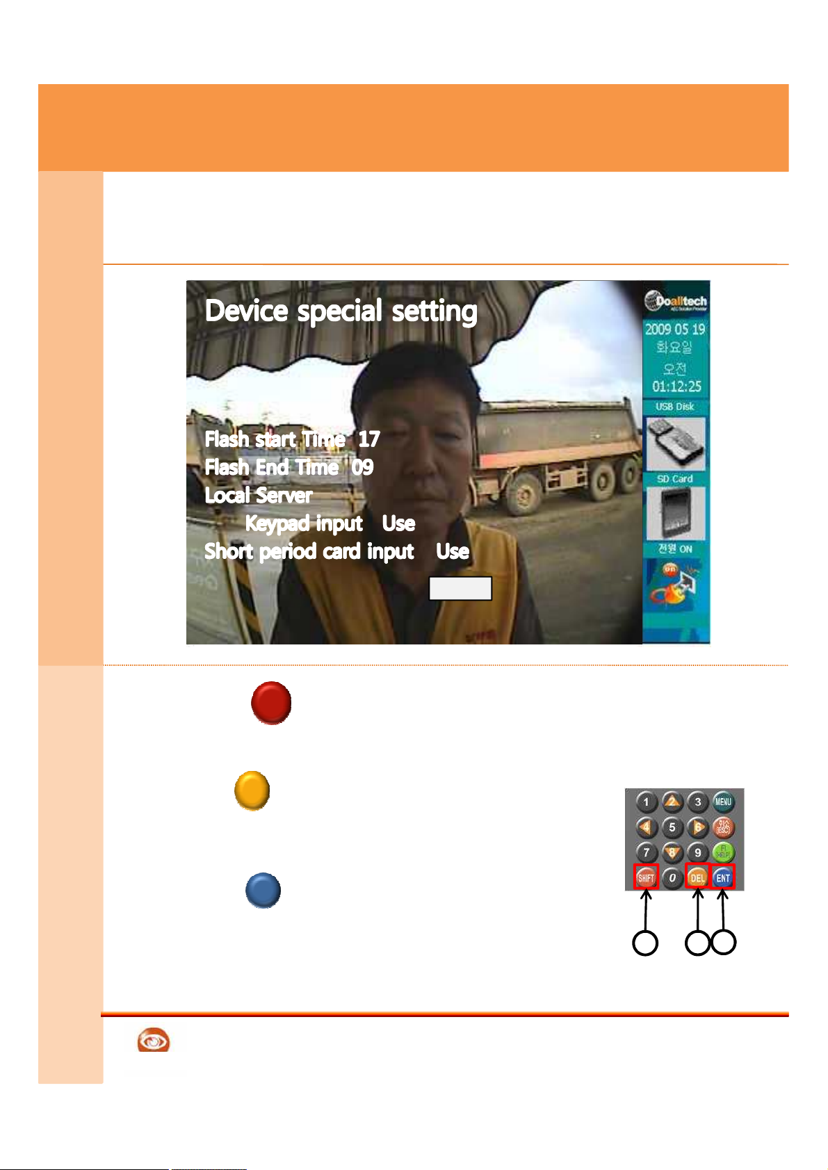
① SHIFT This makes the button to next stage.
– The focus moves to the position of flash end Ti
me when locating in flash start Time. .
② DEL This deletes box contents of button text.
– When there is not contents to be deleted on the
IP input text box, this makes movement to previ
ous text.
③ ENT Input the figure of button selection.
– In the Save button, this makes movement to Me
nu selection page after saving data.
– In the list box, select previous item.
English
This image is just for reference. So it’ can be different from real situation
Screen & Menu function can be changed for high quality improvement
Save
1
SHIFT
DEL
ENT
3
2
13
Reference
Page 14
GATEWARE-EM
Doalltech
K
e
y
p
a
d
C
o
n
t
r
Keypad control explanation
K
e
y
p
a
d
C
o
n
t
r
o
l
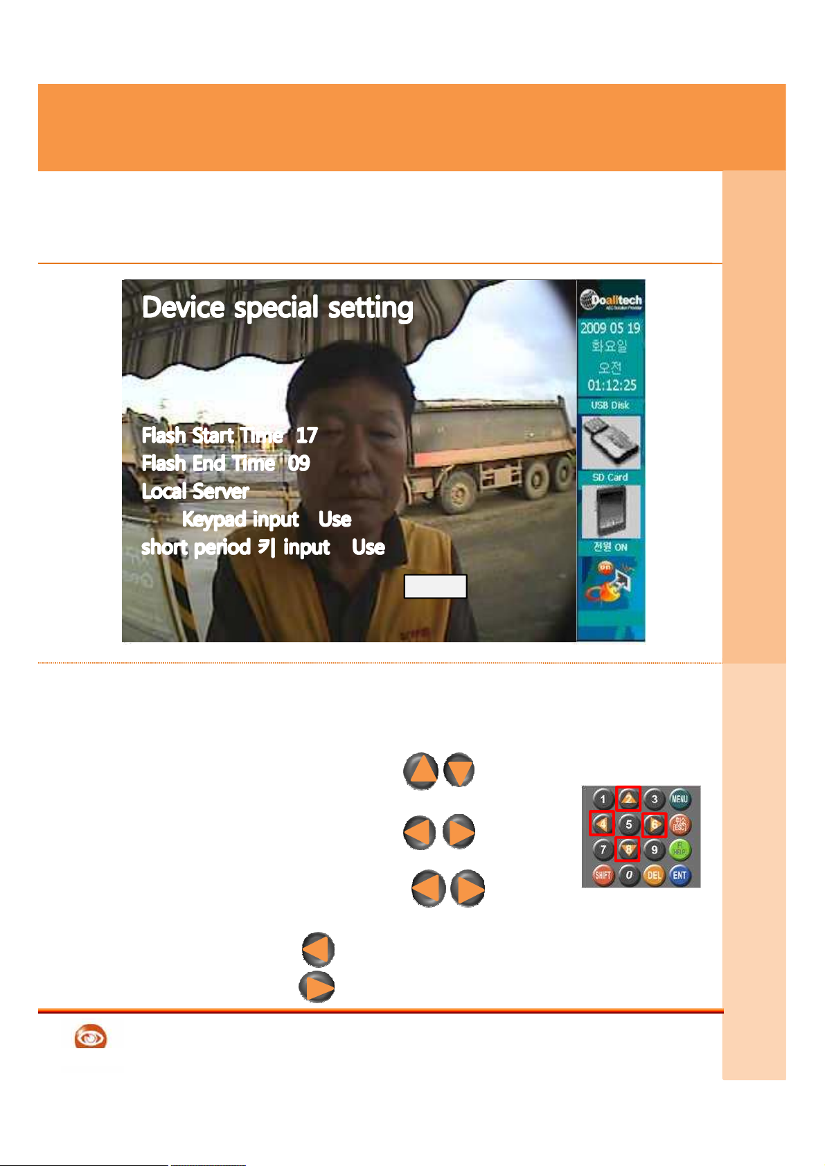
① When inputting Keypad 1~0 in Menu setting
text box, you can input
② In main screen, Keypad 2,4 button :
Controlling Volume up & down
③ In main screen, Keypad 4,6 button
Controlling Screen brightness
④ In project Code, Keypad 4,6 button 6
Changing English code.
– Number key 4 Changing English code A to B
– Number key 6 Changing English code A to Z
English
This image is just for reference. So it’ can be different from real situation
Screen & Menu function can be changed for high quality improvement
Save
2
8
4
6
4 6
4
6
14
Reference
Page 15
GATEWARE-EM
Doalltech
E
n
v
i
r
o
n
.
S
e
t
t
i
1. Menu setting – Enter the Menu
E
n
v
i
r
o
n
.
S
e
t
t
i
n
g
15
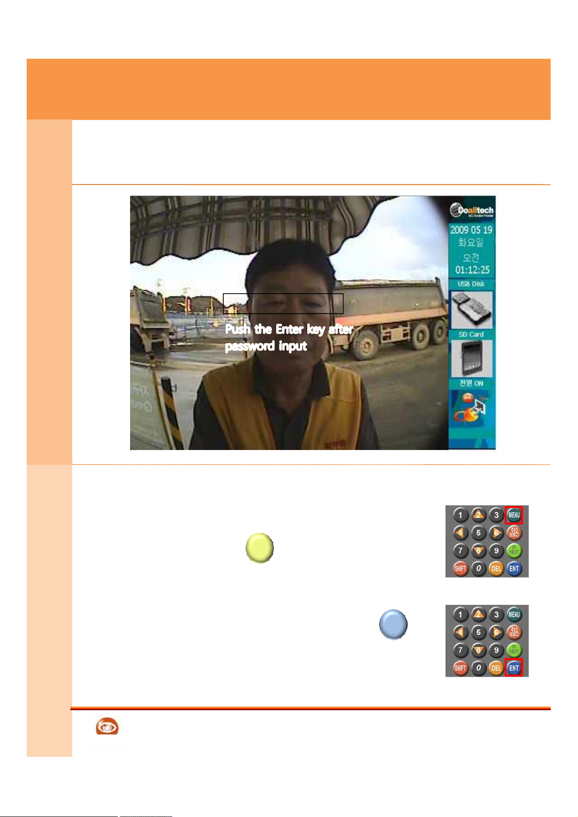
① This is Main Screen. Camera image is
displayed
② Push the MENU button
③ Password prompt is displayed
④ After pushing the Password + ENTER ,
you can see the Product setting Menu
This image is just for reference. So it’ can be different from real situation
Screen & Menu function can be changed for high quality improvement
* Password The first password is ‘0000’
MENU
ENT
English
Reference
Page 16
GATEWARE-EM
Doalltech
E
n
v
i
r
o
n
.
S
e
t
t
i
2. Setting Menu – Selecting item
1. Setting view
2. Default setting
3. Serial Pot setting
4. Relay setting
5. Special setting
ENTER next page
6. LAN setting
7. USB use
8. Time setting
9. password setting
ENTER next page
Menu2
②
E
n
v
i
r
o
n
.
S
e
t
t
i
n
g
16
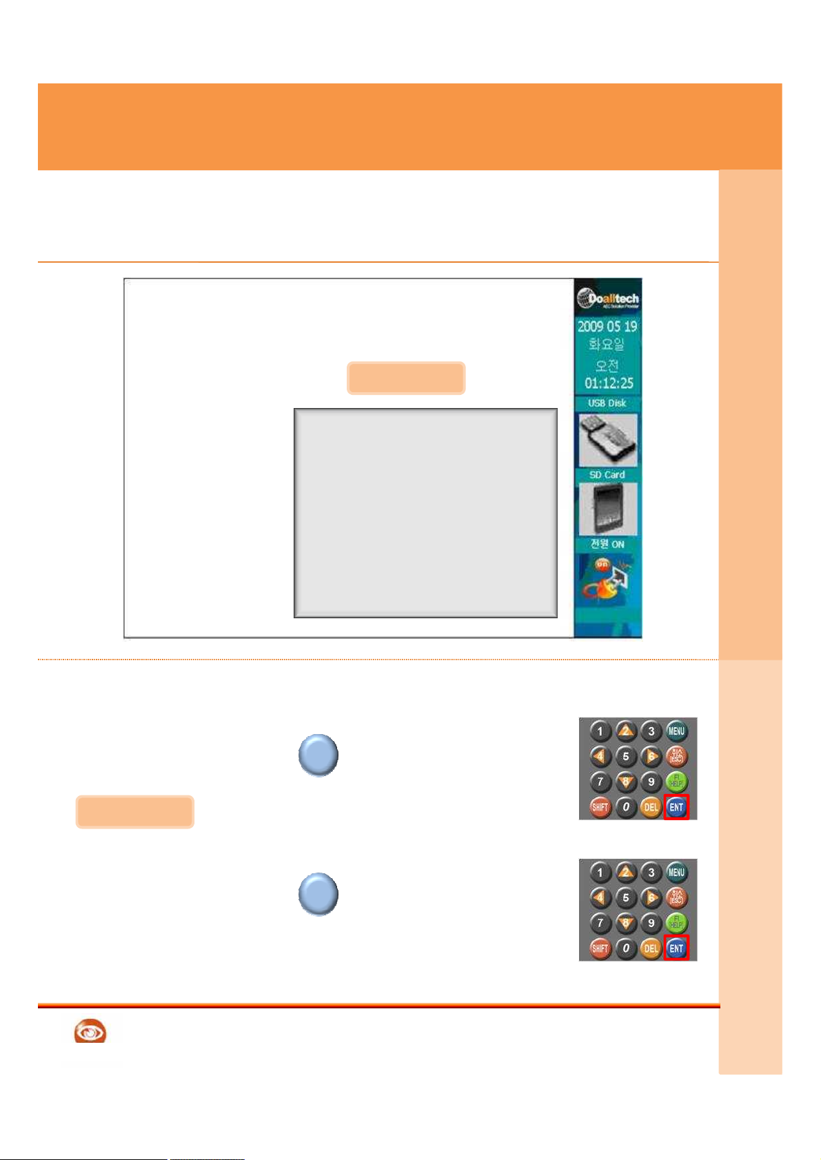
① This is product setting Menu page
② If you push the ENTER button, you can move to next
page
③ This is low Menu of the Product setting
④ If you push the ENTER button, you can move to
next page
⑤ Select the Menu by key pad to move
English
This image is just for reference. So it’ can be different from real situation
Screen & Menu function can be changed for high quality improvement
Menu2
ENT
ENT
④
Reference
Page 17
GATEWARE-EM
Doalltech
E
n
v
i
r
o
n
.
S
e
t
t
i
3. Menu setting – Status check
Device Status info, network status info.
Project codeIBDD2008 IP use status DHCP
Attendance IN/OUT IP Address 192.168.1.100
Camera use 1 Channel Default Gateway 192.168.1.1
Pot1 13.56Mhz Subnet Mask 255.255.255.0
Pot2 Not Use DNS 1 168.126.63.1
Pot3 Not Use DNS 2 168.126.63.2
Pot4 Not Use
Relay1 Not Use
Relay2 Not Use
Relay3 Not Use
Relay4 Not Use
Flash start 16
Flash end 09
E
n
v
i
r
o
n
.
S
e
t
t
i
n
g
17
① Current system status is displayed
② If u push the ESC button,
u can return to Menu selection screen
English
This image is just for reference. So it’ can be different from real situation
Screen & Menu function can be changed for high quality improvement
ESC
Reference
Page 18
GATEWARE-EM
Doalltech
E
n
v
i
r
o
n
.
S
e
t
t
i
4. Menu setting - Default setting
Device Default setting
Project code IBDD2008
Input data in English
Device number 1
Attendance IN/OUT
Camera use 1 Channel
Save
E
n
v
i
r
o
n
.
S
e
t
t
i
n
g
18
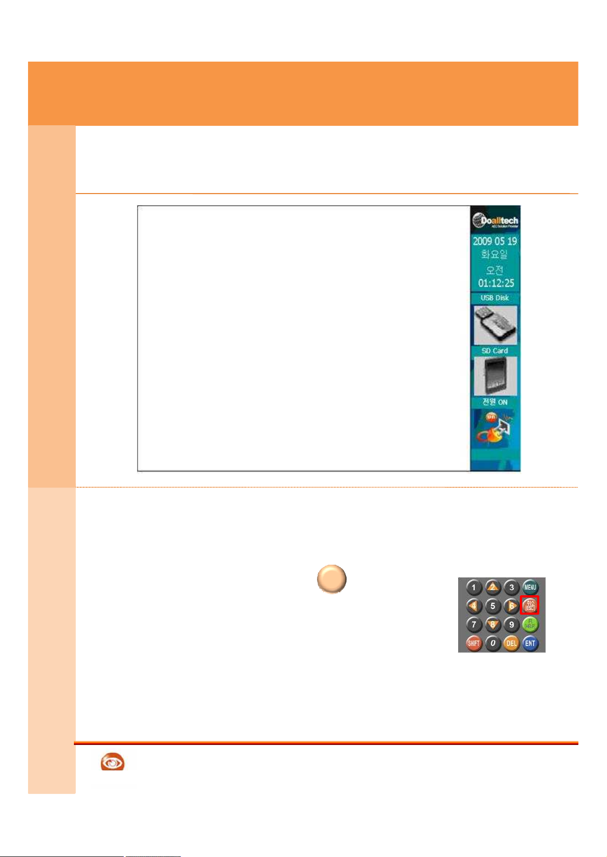
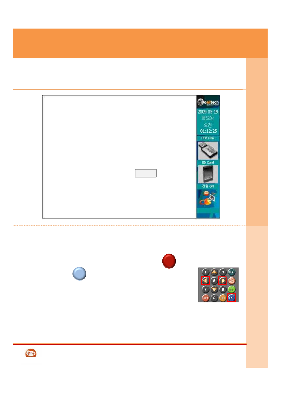
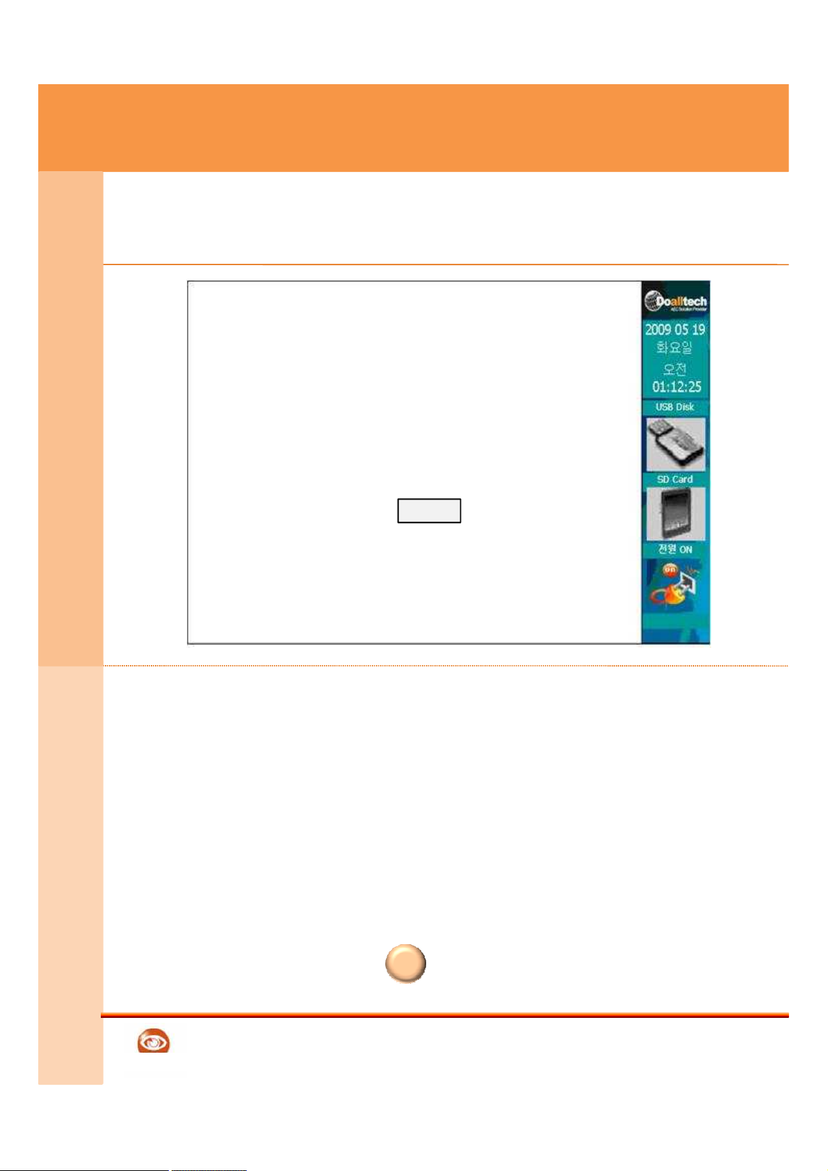
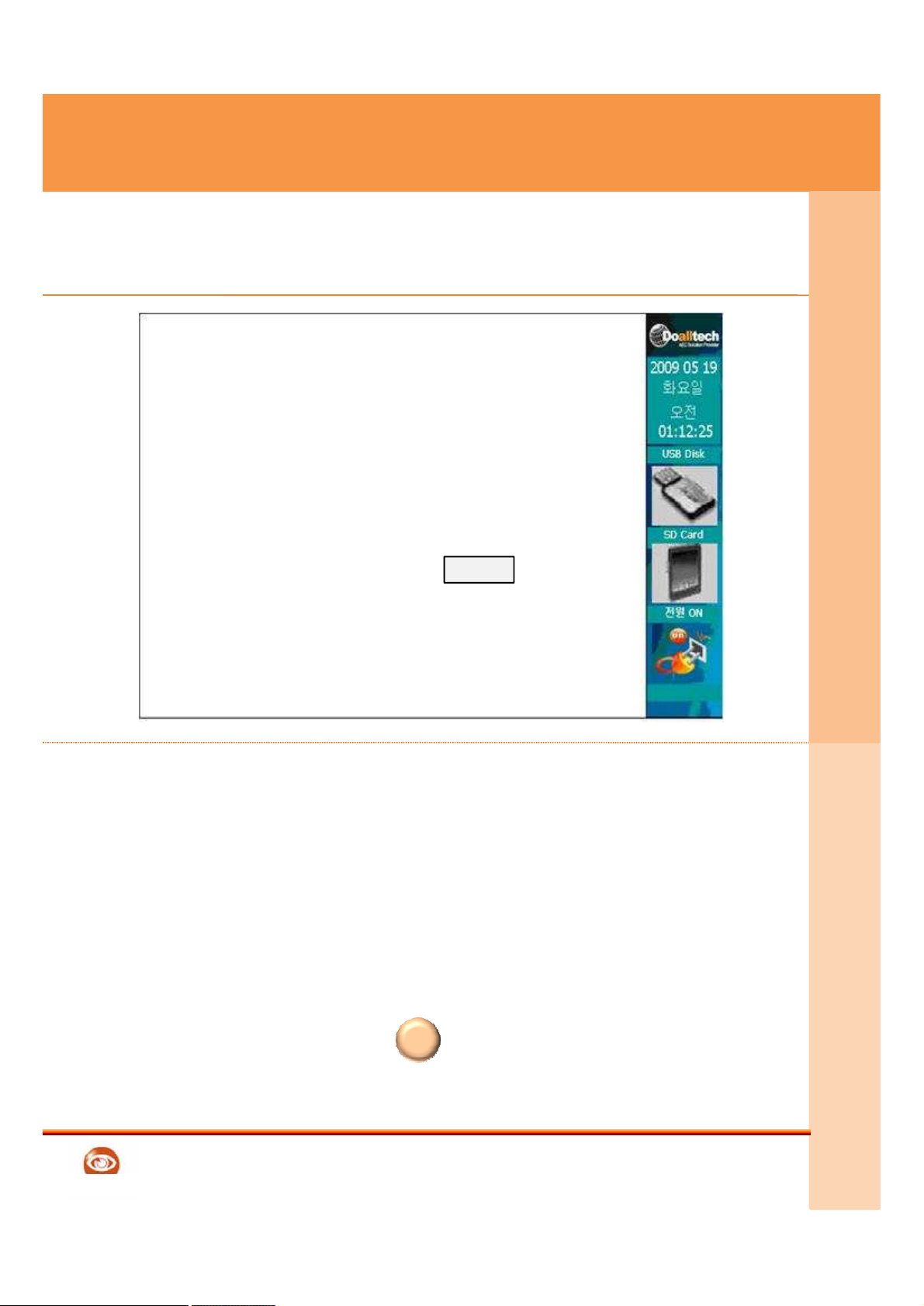
① Default setting Screen of the Product
② Enter the project code
– When inputting English in project code,
Move to the project code by using SHIFT button.
ENTER in inputting English.
This button is used after changing 4, 6 key of
alphabet A indication to English figure.
③ Enter the device number
④ Set the IN/OUT setting
⑤ Set the Camera setting
⑥ Push the Save to save setting code
⑦ If u push the ESC button, you can return to Menu
selection Screen
• Project code English input by enter key / setting number by Keypad number
• In case Device number site, If device are 2ea ,please input each 1,2 number
English
ENT
Reference
SHIFT
Page 19
GATEWARE-EM
Doalltech
E
n
v
i
r
o
n
.
S
e
t
t
i
5. Menu setting – Serial Pot setting
Serial Pot setting
Pot1 13.56Mhz
Pot2 Not Use
Pot3 Not Use
Pot4 Not Use
Save
E
n
v
i
r
o
n
.
S
e
t
t
i
n
g
19
① This is setting Screen of the RFID Serial Pot
② Set the RFID Serial Pot
③ Pot1 is Internal Pot, Pot2,3,4 are External Pot.
④ Set the Additional RFID TYPE.
⑤ Save the setting
⑥ If u push the ESC you can return to setting Menu
English
This image is just for reference. So it’ can be different from real situation
Screen & Menu function can be changed for high quality improvement
ESC
Reference
Page 20
GATEWARE-EM
Doalltech
E
n
v
i
r
o
n
.
S
e
t
t
i
6. Menu setting – Relay setting
Relay setting
Relay1 Allow Port 1
Relay2 Deny Port 1,2
Relay3 Not Use
Relay4 Not Use
Save
E
n
v
i
r
o
n
.
S
e
t
t
i
n
g
20
① Relay setting Screen
② After selecting the Allow(registration), Set the Pot
③ After selecting Deny(rejection), Not applied even though set
the Pot
④ Push the save button for saving setting
⑤ If you push the ESC button, you can return to setting
Menu
• Allow è,Enrolling card Data input, Relay works in Serial Pot
• Deny è Unenrolled card Data input, Relay works in Serial Pot,
English
ESC
Reference
Page 21
GATEWARE-EM
Doalltech
E
n
v
i
r
o
n
.
S
e
t
t
i
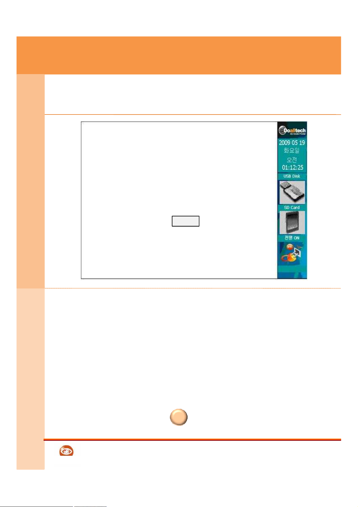
7. Menu setting – Special setting
Device special setting
Flash Start Time 17
Flash End Time 09
Local Server
Keypad input Use
short period key input Use
Save
E
n
v
i
r
o
n
.
S
e
t
t
i
n
g
21
① Flash start Time& End Time setting
② Enter the IP of Local Server
③ The setting of Keypad input use or not
– If it’s possible to enter citizen number without card
④ Short period card setting
– After card check, citizen number is entered from Short
period worker
⑤ Push the Save to save edit code
⑥ If u push the ESC button u can move to next
page
• Inputting 24Time way in Flash start Time
• Example) Start Time PM = 17 , End Time AM 9 = 09
English
ESC
Reference
Page 22
GATEWARE-EM
Doalltech
E
n
v
i
r
o
n
.
S
e
t
t
i
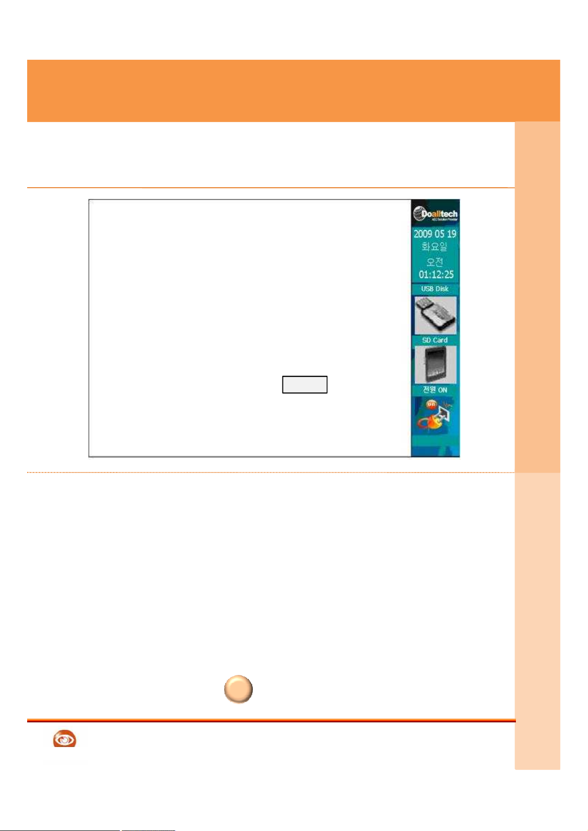
8. Menu setting – LAN setting
LAN setting change
DHCP/STATIC
IP ADDRESS
SUBNET MASK
DEFAULT GATEWAY
DNS 1
DNS 2
Save
E
n
v
i
r
o
n
.
S
e
t
t
i
n
g
22
① Select the DHCP/STATIC use or not
② STATIC Application situation, set the IP ADDRESS
③ Set the SUBNET MASK
④ Set the DEFAULT GATEWAY
⑤ Set the DNS 1 setting
⑥ Set the DNS 2 setting
⑦ Push Save button to save setting Code
⑧ If you push the ESC button, you can return to setting Menu.
English
* DHCP– Internet connection setting method by IP ADDRESS router (Automatically IP allocation)
* STATIC – Internet connection setting method by Direct input of IP ADDRESS
ESC
Reference
Page 23
GATEWARE-EM
Doalltech
E
n
v
i
r
o
n
.
S
e
t
t
i
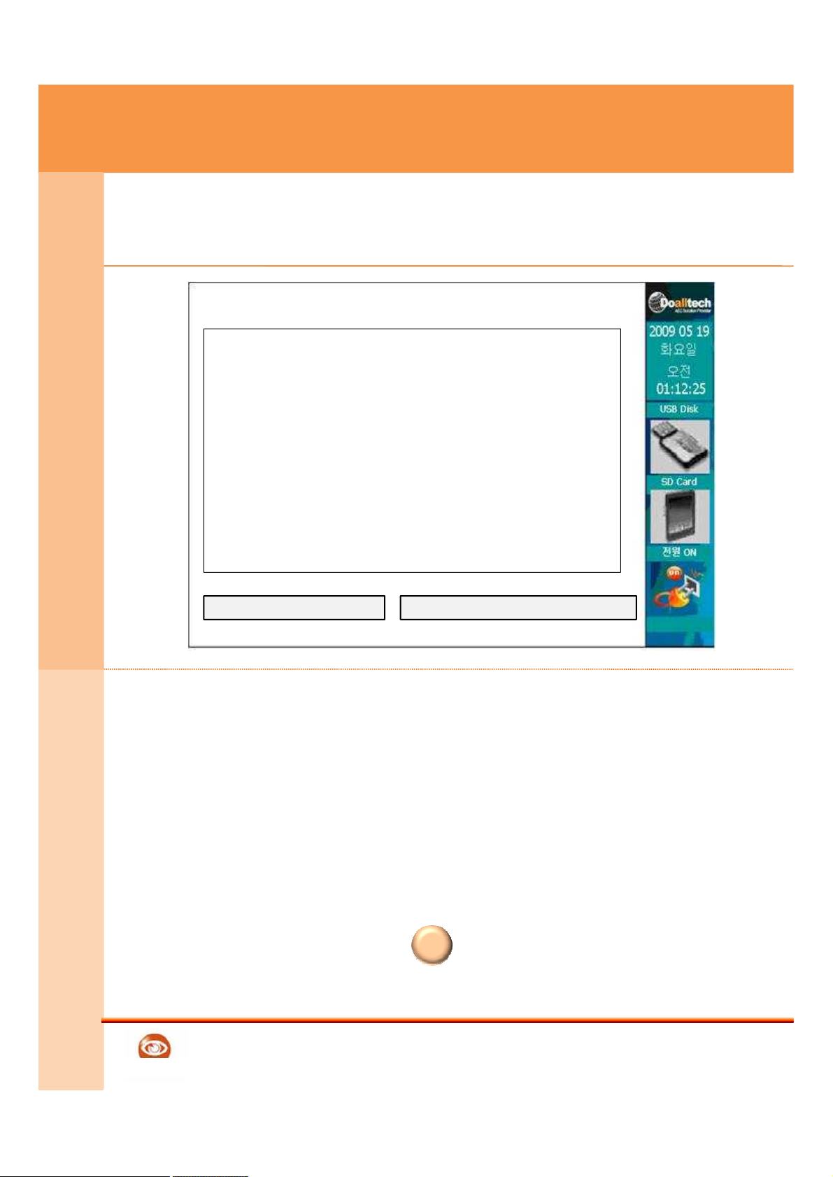
9. Menu setting – by using USB
USB Data in&output
E
n
v
i
r
o
n
.
S
e
t
t
i
n
g
23
① USB application setting Screen
② Connect the USB memory to product
③ Save the worker data by pushing the Worker data save button
④ Select the save button to copy worker attendance data to
Attendance Data USB by memory stick
⑤ If you push the ESC button, you can return to setting
Menu
English
C/S Version is only available
Input output from Gateware folder Data of USB memory
Save worker Data
copy to attendance Data USB
ESC
Reference
Page 24
GATEWARE-EM
Doalltech
E
n
v
i
r
o
n
.
S
e
t
t
i
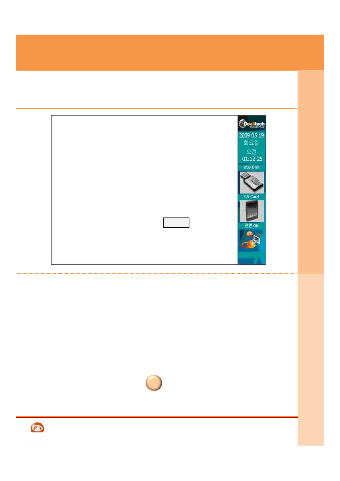
10. Menu setting – Time setting
Current Time & Time zone setting
2009 year 5 month 14 day
12 hour 15 min 30 sec
(GMT+09:00)Seoul
Korea Standard Time
Save
E
n
v
i
r
o
n
.
S
e
t
t
i
n
g
24
① Enter the current year, month, day
② Enter the current hour, min, second
③ Select the Standard Time zone
④ Push the Save button for save setting
⑤ If you push the ESC button, you can return to
setting Menu
English
This image is just for reference. So it’ can be different from real situation
Screen & Menu function can be changed for high quality improvement
ESC
Reference
Page 25
GATEWARE-EM
Doalltech
E
n
v
i
r
o
n
.
S
e
t
t
i
11. Menu setting – Password
Password change
Save
E
n
v
i
r
o
n
.
S
e
t
t
i
n
g
25
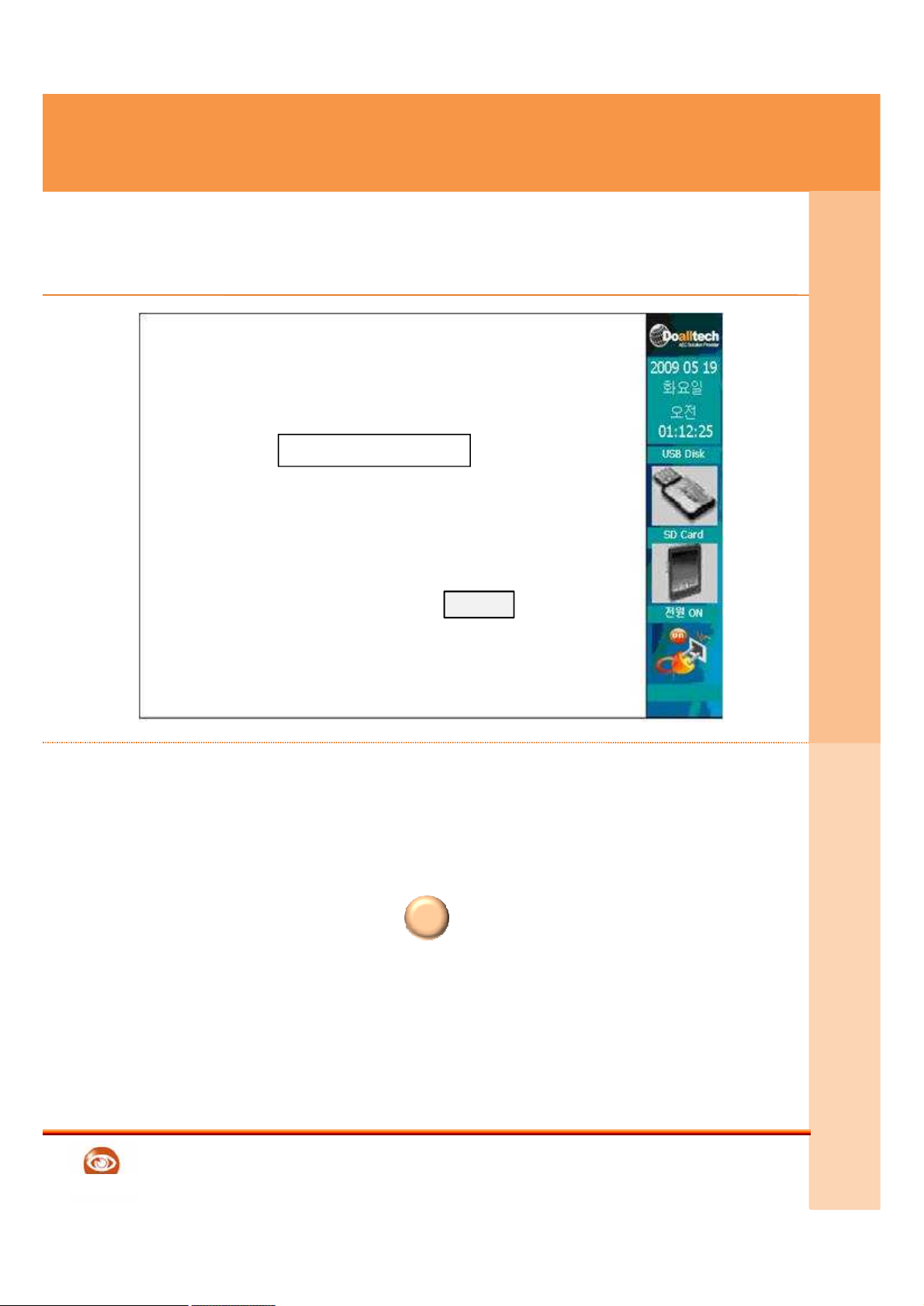
① Product password setting
② Pushing the Save button to save the password
③ If you push the ESC button, you can return to
setting Menu
.
English
This image is just for reference. So it’ can be different from real situation
Screen & Menu function can be changed for high quality improvement
Default setting password is 0000.
ESC
Reference
Page 26
GATEWARE-EM
Doalltech
R
e
f
e
r
e
n
c
e
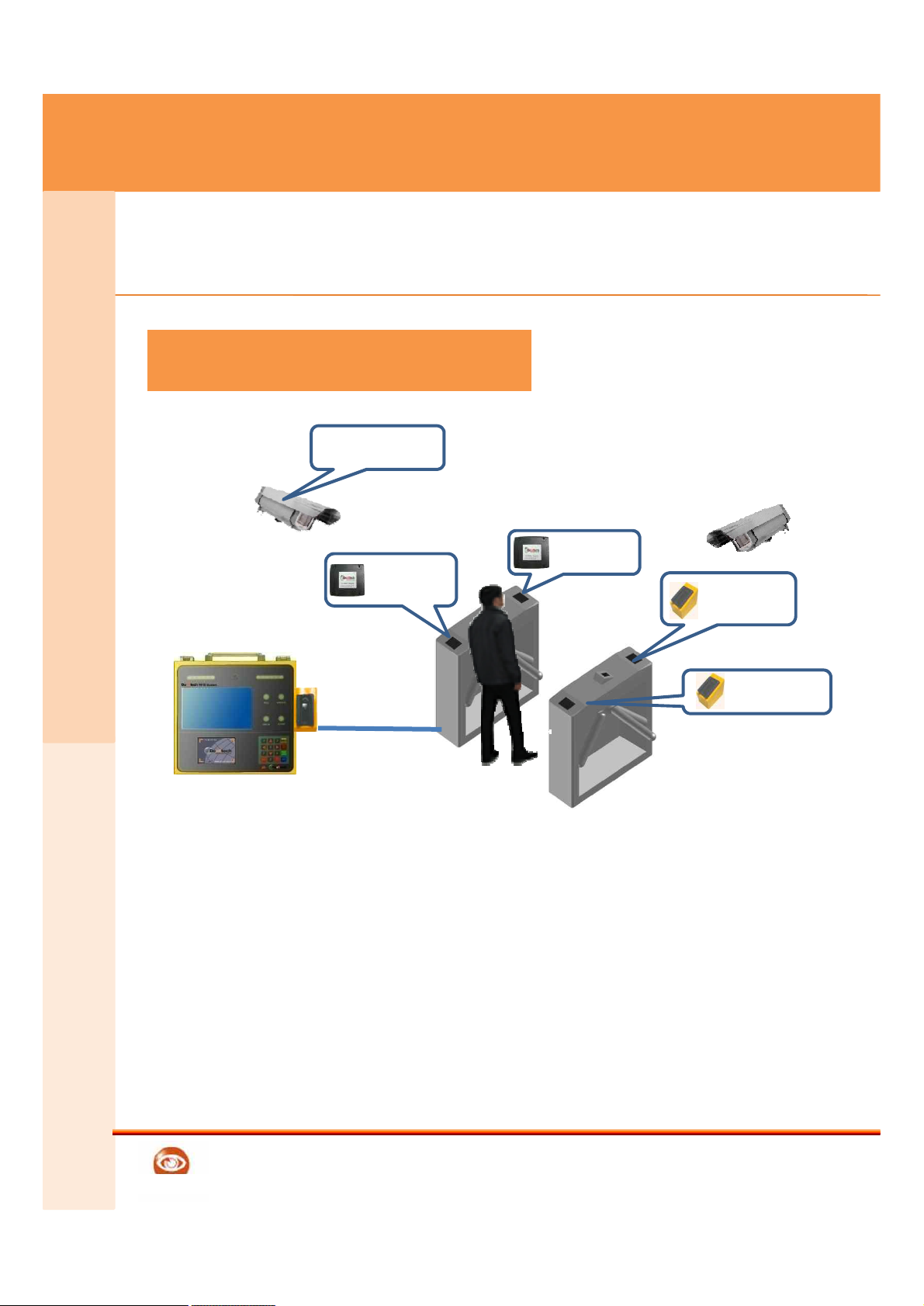
1. External Interlocking device - Turn-Gate
13.56Mhz
READER
13.56Mhz
READER
CCTV for Safety
management
Turnstile Gate SystemTurnstile Gate System
Finger Vein
READER
26
English
This is a use example. This can be composed differently in case of actual application.
Photo 1.
①Using Various RFID TYPE(13.56Mhz) and
Finger Vein TYPE at the same time is available
②When worker check the scan card, device takes a picture by
Safety CCTV automatically
Photo 1 Turnstile Gate System
Reference
Finger Vein
READER
Page 27
GATEWARE-EM
Doalltech
2. External Interlocking device – Composition item
R
e
f
e
r
e
n
c
e
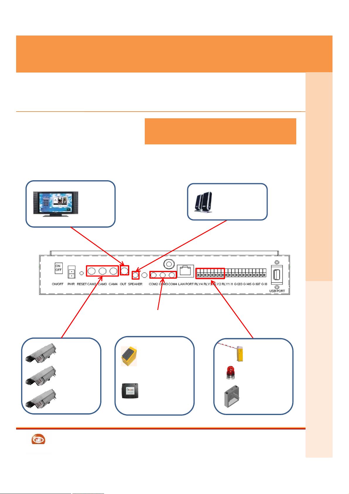
External Interlocking productExternal Interlocking product
External
Speaker
External
Monitor
27
English
Can interlock with another various devices
Camera1
Camera2
Camera3
RFID
13.56Mhz
Crossing
barrier for car
Flashlight
Turnstile Gate
System
Reference
Finger Vein
READER
Page 28
GATEWARE-EM
Doalltech
R
e
f
e
r
e
n
c
e
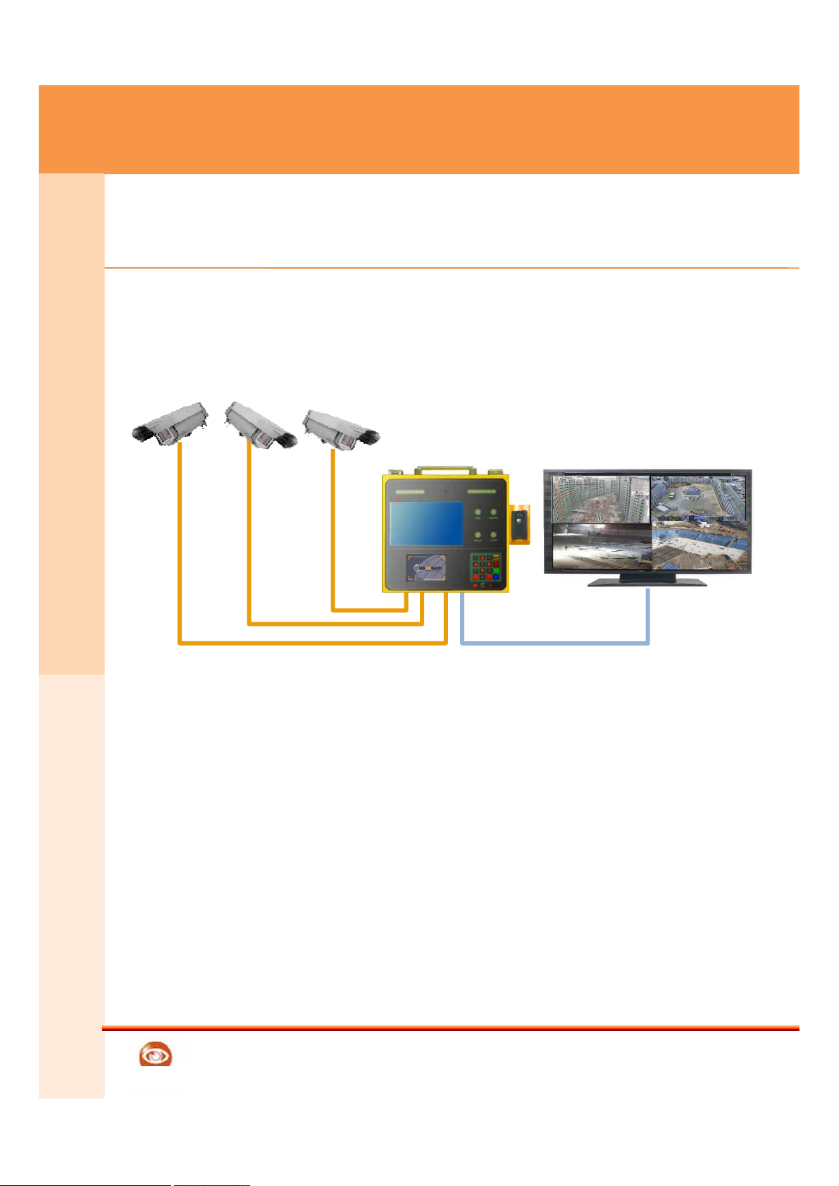
1. Additional function
• Transmission of field pictures through network aft
er image capturing of 1/4 channel camera.
English
This is a use example. This can be composed differently in case of actual application.
28
Reference
• Transmission of field pictures through network aft
er image capturing of 1/4 channel camera.
Page 29
GATEWARE-EM
Doalltech
Case 1
System is not working
→ Please check the Power supply connection
→ Please check the Battery charge status
2. F A Q
R
e
f
e
r
e
n
c
e
Case 2
Data down and upload don't work.
→ Please check the internet connection
→ Please check the Modem & Network status
29
English
Please check FAQ before A/S Request
29
Case 3
Camera is not displayed
→ Please check the Camera connection
→ Please check the Menu setting
Case 4
RFID card recognition doesn't work.
→ Please check the RFID Reader connection
→ Please check the Menu setting
Case 5
There is no system response. (EX : Time sign stops)
→ Please push the RESET button and restart
Reference
Page 30
GATEWARE-EM
Doalltech
Case 6
LCD Screen is monotonous in the state of ash or black color.
→ push the RESET or power switch to restart
→ When being occurred same symptom after re-start, please contact to Doall
tech and then confirm it
R
e
f
e
r
e
n
c
e
2. F A Q
Case 7
There is no sound during working
→ Please check the volume button by key pad
→ When being occurred same symptom after re-start, please contact to Doall
tech and then confirm it.
English
Please check FAQ before A/S Request
* Battery is consumption goods & 6months A/S warranty available
Case 8
The battery does not be charged.
→ Please check the Power supply cable, Adapter, internal battery terminal
connection
→ Change the old battery to new battery
Case 9
There is error message window On the Screen
→ Please press the ENT button of keypad.
(When the program is abnormal, it will be worked again after closing).
→ In case the keypad does not be inputted, please start again by using
RESET button or power switch.
→ When being occurred same symptom after re-start, please contact to Doal
ltech and then confirm it.
Reference
Page 31

GATEWARE-EM
Doalltech
Error type
Cause and Solution
In case of Power
supply failure
Please check the Power supply cable.
Please check the 220 volt as right voltage
Please check the electronic status of receptacle
Please check the System Power supply Cable
3. Before A/S Request
R
e
f
e
r
e
n
c
e
31
In case system is not
Working
Please check loss of Internal supply item
Please check Error message from Monitor
In case of
Monitor Screen
Shutting down by
itself
Please check Monitor Power supply cable
Please check the Monitor Cable connection
Please Check the system Power supply
In case of Camera
screen failure
Please check the Camera cable connection
Please check the Menu setting
English
31
Page 32

GATEWARE-EM
Doalltech
Error type
Cause and Solution
In case internet is
not working
Please network setting in LAN setting
Menu
Please check LAN cable connection
Please contact with internet company
In case Router is not
Please check the router motion lamp,
Power supply cable & Adapter
Please check LAN cable connection
R
e
f
e
r
e
n
c
e
3. Before A/S Request
In case Router is not
working
Please check LAN cable connection
Please check Router menu setting
In case External
Relay is not working
(Turn gate,Flash light)
Please check Power supply cable
Please check the Relay Data cable
connection
Please setting code from Relay setting
Menu
In case of not
recognizing the RFID
tag
Please check the RFID Reader cable
connection
Please check the RFID Reader setting from
Serial Pot Menu
English
Page 33

GATEWARE-EM
Doalltech
Error type
Cause and Solution
Key pad doesn’t
work
Please check Key pad cable connection
Please make sure to push key pad
Please confirm whether input at current
Menu is possible. (There are keys that do
not be operated at partial menu)
Please check the Flash cable connection
3. Before A/S Request
R
e
f
e
r
e
n
c
e
33
If flash lamp is not
turned on
Please confirm the setting figure of
related flash in the setting Menu
Please check Flash lamp status
In case power supply
and status indication
of RFID recognition
lamp do not turned
on
Please check the Lamp connection cable
Please confirm whether RFID recognition
is correct
Please confirm whether the system is
turned on.
In case other
operations are not
correct
Please after shutting down, restart
Please after checking error type, contact
with doalltech
English
33
Page 34
GATEWARE-EM
Doalltech
R
e
f
e
r
e
n
c
e
4. Product Size - Hardware
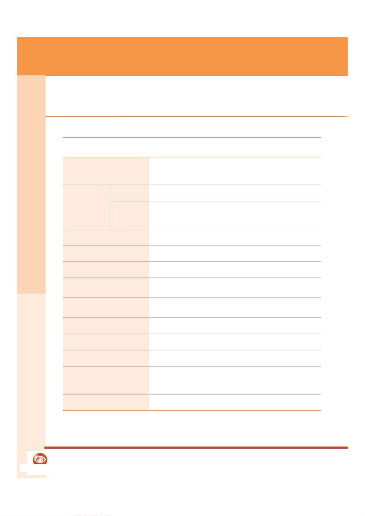
Hardware
CPU
Processor Marvell PXA320-P
(ARM11 Core 806Mhz)
Memory
RAM
133Mhz DDR SDRAM 512MByte
Nand
Flash
NAND Flash 128MByte
EPLD
Lattice isp MACH LC4128V
Display
800 X 480 (7” Wide TFT Color LCD)
English
Product specification can be changed for high quality improvement
Touch Screen
Touch Screen Controller
SD / MMC
SD / MMC 1 Slot
LAN
10/100 M Ethernet (91C111)
Camera
CCD Camera
Audio
AC97 (WM9712) Internal x 2, External x 1
UART
Max3232 (Debugger x1, Serial x3)
Video Controller
Video IN x 3, Video OUT x 1
(Techwell TW2835)
KEY PAD
4x4 Push Button
Reference
Page 35

GATEWARE-EM
Doalltech
RFID
ATMEGA 13.56Mhz Reader
Finger Vein
FDV-566,567
USB
Host
USB 1.1 Host
Client
USB 2.0 Client
CPU-JTAG
JTAG Emulator – 20pin
E-JTAG
JTAG Emulator – 8pin
Relay
Signal Out Relay x 4
Sensor
Signal Input Sensor x 8
4. Product Size - Software
R
e
f
e
r
e
n
c
e
35
Battery
Li-ion 14V, 8800 mAh
LED
Color LED x 3
Flash
Light Flash x 2
English
Product specification can be changed for high quality improvement
35
Software
O/S
Windows CE 5.0 Core
Application
Doalltech GatewareEM / GatewareCS
Reference
Page 36
GATEWARE-EM
Doalltech
R
e
f
e
r
e
n
c
e
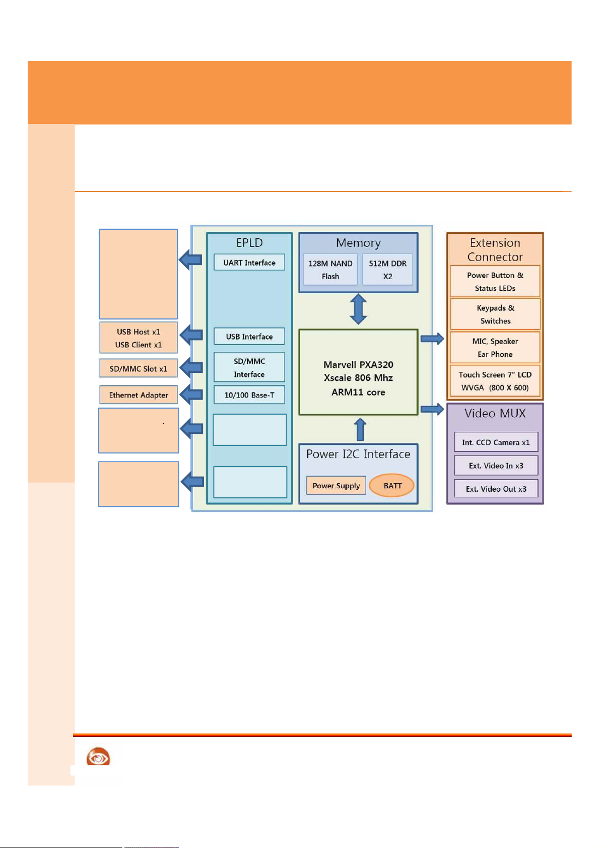
4. Product Size – Block Diagram
Int. Serial Port x1
(13.56Mhz RFID)
Ext. Serial port x3
(13.56Mhz RFID
Reader,
Finger Vein Reader)
Debugger port x1
Photo Sensor,
English
Product specification can be changed for high quality improvement
Turnstile Gate,
Vehicle Control Bar
Photo Sensor,
Roof Coil Sensor
Relay X4
Sensor X8
36
Reference
Page 37

GATEWARE-EM
Doalltech
5. FCC RF INTERFERENCE STATEMENT
R
e
f
e
r
e
n
c
e
FCC RF INTERFERENCE STATEMENT
NOTE :
This equipment has been tested and found to comply with the limits for a Class B
digital device, pursuant to Part 15 of the FCC Rules. These limits are designed to
provide reasonable protection against harmful interference in a residential
installation.
This equipment generates, uses and can radiate radio frequency energy and, if
not installed and used in accordance with the instructions, may cause harmful
interference to radio communications. However, there is no guarantee that
interference will not occur in a particular installation.
37
English
Product specification can be changed for high quality improvement
Reference
FCC RF INTERFERENCE STATEMENT
NOTE :
This equipment has been tested and found to comply with the limits for a Class B
digital device, pursuant to Part 15 of the FCC Rules. These limits are designed to
provide reasonable protection against harmful interference in a residential
installation.
This equipment generates, uses and can radiate radio frequency energy and, if
not installed and used in accordance with the instructions, may cause harmful
interference to radio communications. However, there is no guarantee that
interference will not occur in a particular installation.
If this equipment does cause harmful interference to radio or television reception
which can be determined by turning the equipment off and on, the user is
encouraged to try to correct the interference by one or more of the following
measures.
- Reorient or relocate the receiving antenna.
- Increase the separation between the equipment and receiver.
- Connect the equipment into an outlet on a circuit different from that to
which the receiver is connected.
- Consult the dealer or an experienced radio, TV technical for help.
- Only shielded interface cable should be used.
Finally, any changes or modifications to the equipment by the user not expressly
approved by the grantee or manufacturer could void the users authority to
Operate such equipment
Page 38
GATEWARE-EM
Doalltech
5. FCC RF INTERFERENCE STATEMENT
R
e
f
e
r
e
n
c
e
38
English
Product specification can be changed for high quality improvement
Reference
Page 39
GATEWARE-EM
Doalltech
R
e
f
e
r
e
n
c
e
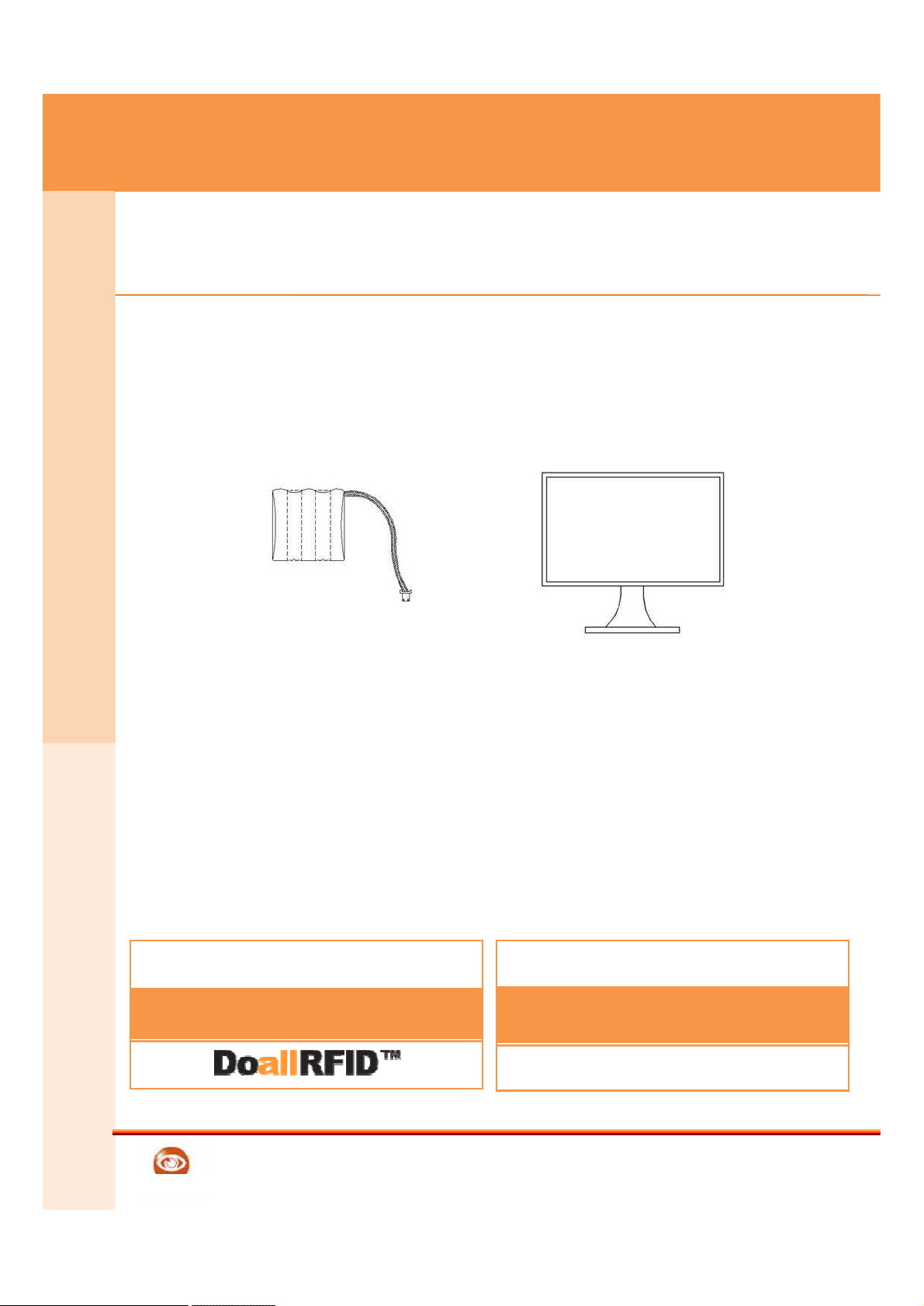
Additional charge item
English
Picture size of each item can be different from real product size,, Some part items can
be changed depending on the situation
Battery
AV LCD MONITOR
39
Internet homepage
www.doalltech.com
Contact
0707-018-5900
02) 555-9779
Ubiquitous team
Reference
 Loading...