

Page 1

Supernova™ Flex
Installation Guide
User Guide
Service Guide
Contents
A Safety Instructions / Instructions de sécurité ······················· 2
B Required tools ····························································· 4
C Box contents ······························································· 5
D Planning ···································································· 6
E Mounting screen assembly ············································· 8
F Setting new stop positions ··············································· 14
G Remote control button functionality ··································· 16
H Communication ···························································· 17
I Troubleshooting ····························································· 20
J Cleaning ······································································ 21
K Sales & delivery terms ··················································· 22
L Planning guide ······························································ 24
Page 2
Page 2
A Safety Instructions / Instructions de sécurité
A1 Important Safety Instructions (EN)
Read these instructions.
Keep these instructions.
Heed all warnings.
Follow all instructions.
Clean only with dry cloth.
Do not block any ventilation openings. Install in accordance with the manufacturer’s
instructions.
Do not defeat the safety purpose of the grounding-type plug. A grounding type plug
has two blades and a third grounding prong. The third prong is provided for your
safety. If the provided plug does not fit into your outlet, consult an electrician for
replacement of the obsolete outlet.
Protect the power cord from being walked on or pinched particularly at plugs,
convenience receptacles and the point where they exit from the apparatus.
Unplug this apparatus during lightning storms or when unused for long periods of
time.
WARNING! To reduce the risk of fire or electric shock, do not expose this apparatus
to rain or moisture. Do not operate screen before it is installed on wall.
The apparatus shall not be exposed to dripping or splashing and no objects filled
with liquids, such as vases, shall be placed on the apparatus.
Follow all installation instructions. Incorrect installation can lead to severe
injury and/or permanent product damage and will invalidate the dnp warranty.
Be sure that the wall studs or other mounting fixtures are suitable for mounting the
screen and …
Be sure that the screen is mounted correctly and securely to the wall or the dnp
warranty will be invalidated.
The mains plug, extension cord, appliance inlet or power strip is used as the
disconnect device, the disconnect device must remain readily operable.
The screen is a class I construction and shall be connected to a mains socket outlet
with protective earthing connection. Do not install without a ground connection.
Do not pull or tug on screen when mounted on wall.
Do not restrict the screen from moving.
Do not scratch or bend screen material during handling.
Operate within specified temperature and humidity range (see section I).
Do not attempt to disassemble any part of the screen (electric shock hazard).
Do not permit children to play with screen controls.
Examine the screen for imbalance or signs of wear during operation. If needed,
adjust before operating .
Page 3
Page 3
A2 Instructions de sécurité importantes (FR)
Lire ces instructions.
Conserver ces instructions.
Tenir compte de tous les avertissements.
Suivre toutes les instructions.
Nettoyer uniquement avec un chiffon sec.
Ne bloquer aucune ouverture de ventilation. Installer conformément aux instructions
du fabricant.
Ne pas négliger la sécurité que procure une prise avec raccordement à la terre.
Une prise avec raccordement à la terre comporte deux fiches plus une troisième
reliée à la terre. Cette troisième fiche est là pour votre sécurité. Si le connecteur
fourni ne s’insère pas dans votre prise de courant, consulter un électricien afin de la
remplacer.
Protéger le cordon d’alimentation principale afin qu’il ne soit pas écrasé ou pincé,
en particulier au niveau des prises de courant et au point de sortie de l’appareil.
Débrancher cet appareil en cas d’orage avec risque de foudre ou lorsqu’il n’est pas
utilisé pendant des péri odes pr ol ong ées .
ATTENTION! Pour réduire le risque d’incendie ou de choc électrique, ne pas
exposer cet appareil à la pluie ou à l'humi di t é. Ne pas faire fonctionner l'écran avant
qu'il ne soit installé sur le mur.
L’appareil ne doit pas être exposé à un égouttement ou des éclaboussures et il
convient de ne placer aucun objet contenant un liquide, comme un vase, sur
l’appareil.
Suivez toutes les instructions d'installation. Une installation incorrecte peut causer
de sévères blessures et/ou des dommages importants au produit et invalider la
garantie du produit.
Assurez-vous que le matériel d'installation correspond bien à la nature du support
et des vis de fixation.
Assurez vous que l'écran est installé correctement et solidement au mur ou la
garantie dnp sera invalidée.
La prise secteur, le cordon, l’alimentation de l’appareil ou la barrette d’alimentation
sont utilisés comme dispositifs de déconnexion et doivent être facile à actionner.
L’écran est de classe I et doit être connecté à une prise secteur disposant d’une
mise à la terre. Ne pas installer le système en l’absence de prise de terre.
Ne pas tirer sur l’écran une fois qu’il est monté sur le mur.
Ne pas empêcher l'écran de bouger.
Ne pas érafler ou courber le matériel de l’écran lors des manipulations.
Utiliser l’écran selon les plages de température et d’humidité spécifiées (cf. section
I).
Ne pas tenter de démonter quelque partie de l’écran que ce soit (danger de choc
électrique).
Ne pas laisser les enfants jouer avec les commandes de l’écran.
Examiner l’écran afin de détecter tout déséquilibre ou signe d’usure pendant le
fonctionnement. Si nécessaire, ajuster avant de faire fonctionner.
Page 4
Page 4
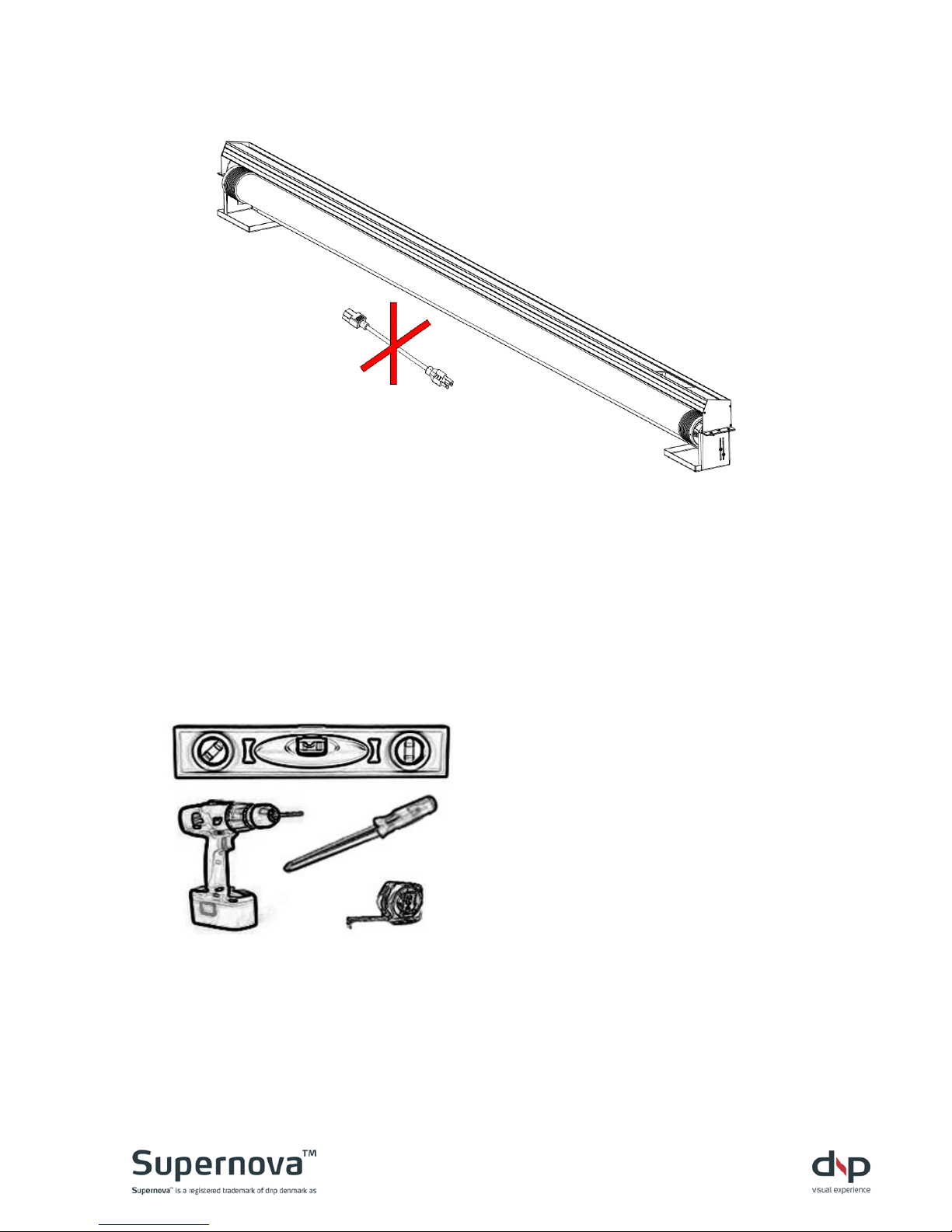
B Required tools
You will need the following tools:
Level
Phillips screwdriver
Power drill
Tape measure
WARNING! Do not connect power
until screen assembly is
completely mounted.
Page 5
Page 5
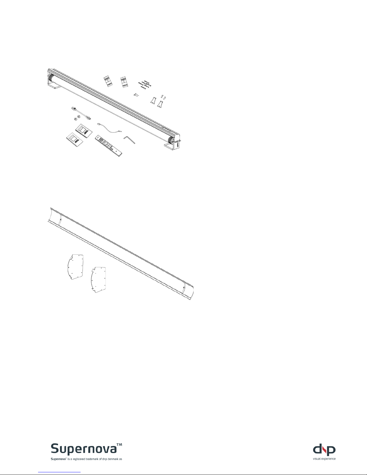
C Box contents
Box 1
Box 2
Check box for:
Box 1 – Screen
1 Installation manual (this
document)
1 User manual
1 Screen assembly
1 Remote control
1 CR2032 3V battery
2 Wall brackets
2 #8-32 screws for securing
screen to wall bracket
4 #8 x 2½” wall mounting
screws
2 #8 x 2½” leveling screws
2 Washers for leveling screws
2 End-caps for lower bar
1 Power cable
1 IR cable with clip
Box 2 - Cover
1 Cover
2 Security clips
2 #8-32 screws for security clip
2 Washers for security clip
2 End-plates for on-wall
version
Page 6
Page 6
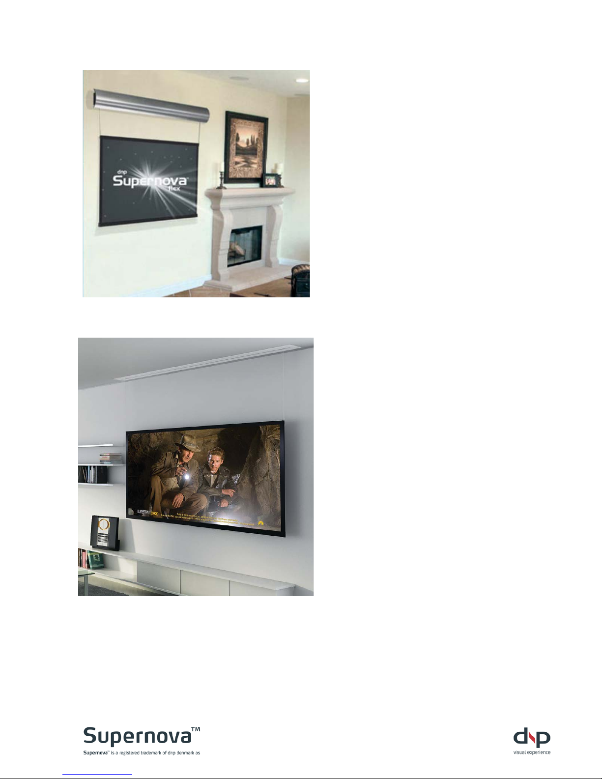
D Planning
See also section J Planning guide
D1
Planning screen location
a. Locate wall studs or other
structural member suitable for
bracket mounting.
Note: Select studs for mounting
that are at least 4” [101 mm] in
from end of cover.
b. Leave enough clearance at ends
to permit access for removing
screws from shipping fixtures.
c. Leave enough top clearance to
tighten security screws on top of
wall brackets.
d. Custom spacers are available if
the screen assembly needs to be
spaced further away from the wall
to clear obstructions when rolling
down.
NOTE! See separate manual for inceiling installation!
Page 7
Page 7
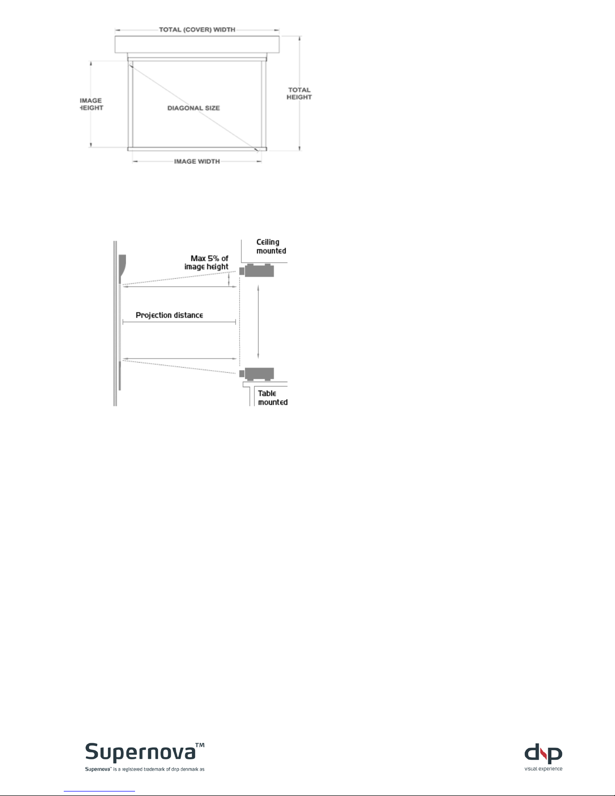
D2
Checking screen dimens ions
a. Determine space requirements for
installation.
b. Refer to section J Planning guide
c. Ensure proper clearances.
_____
D3
Planning projector location
a. The projector can be positioned
freely on a vertical centerline,
perpendicular to the screen, up to
5% above (ceiling mounted) or up
to 5% below (table mounted) the
image area.
b. Projection distances must be
based on manufacturer’s
specifications for the exact model
and lens choice.
Page 8
Page 8
E Mounting screen assembly
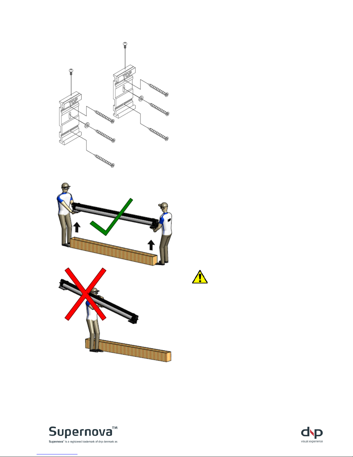
E1
Unpacking bracket hardware
a. Unpack two wall brackets.
b. Unpack mounting and securing
hardware.
E2
Lifting screen from box
a. Use two people to lift screen from
box.
b. Lift from box using the two
shipping fixtures at the ends as
handles.
Warning! Do NOT lift from
middle of screen.
Page 9
Page 9
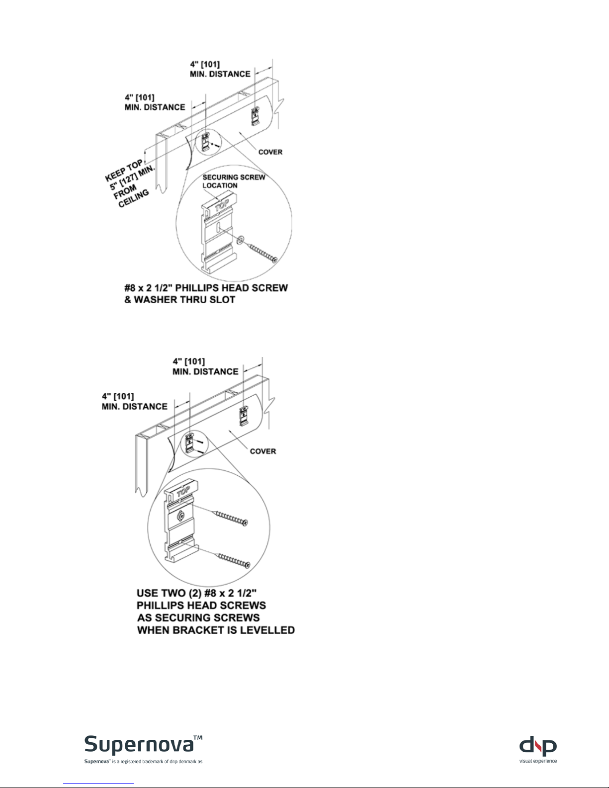
E3
Leveling brackets
a. After planning screen location...
(using section J Plan ning guide)
b. Mount wall bracket with securing
screw at top of bracket.
c. Loc ate wall brackets at least 4”
[101 mm] in from end of cover.
d. Level wall brackets to each other
and tighten leveling screws.
____
E4
Securing wall brackets
a. Secure each wall bracket with two
wall mounting screws.
b. Tighten all screws.
Page 10
Page 10
E5
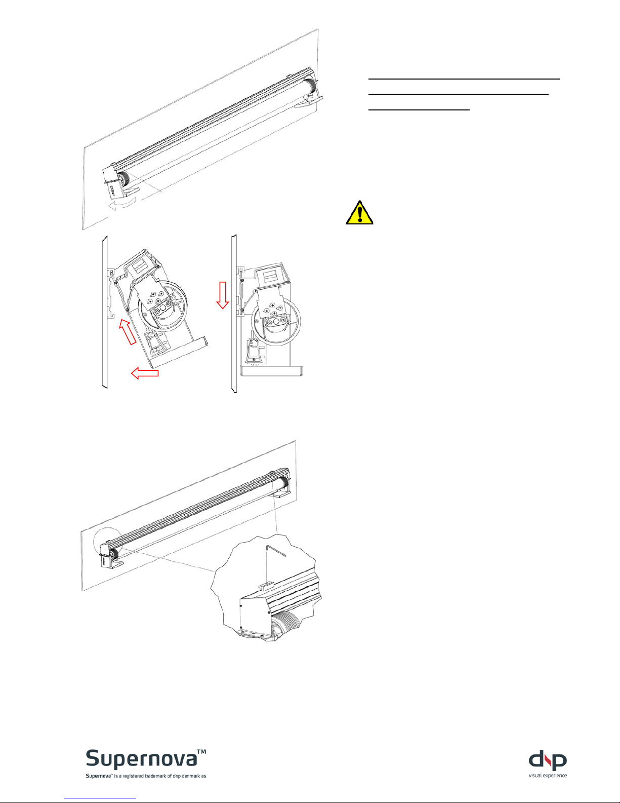
Mounting screen
a. Leave shipping fixtures attached
to ends while mounting screen
assembly to wall.
b. Using two people, grasp fixtures,
lift (1), rotate (2), and seat (3)
screen assembly into wall
brackets.
Warning! Be sure that screen
assembly is securely seated
before releasing grip.
_____
E6
Securing screen assembly
a. Ensure that screen is properly
seated into both wall brackets.
b. Use securing screws to tighten
down screen assembly to wall
brackets.
1
2
3
Page 11
Page 11
E7
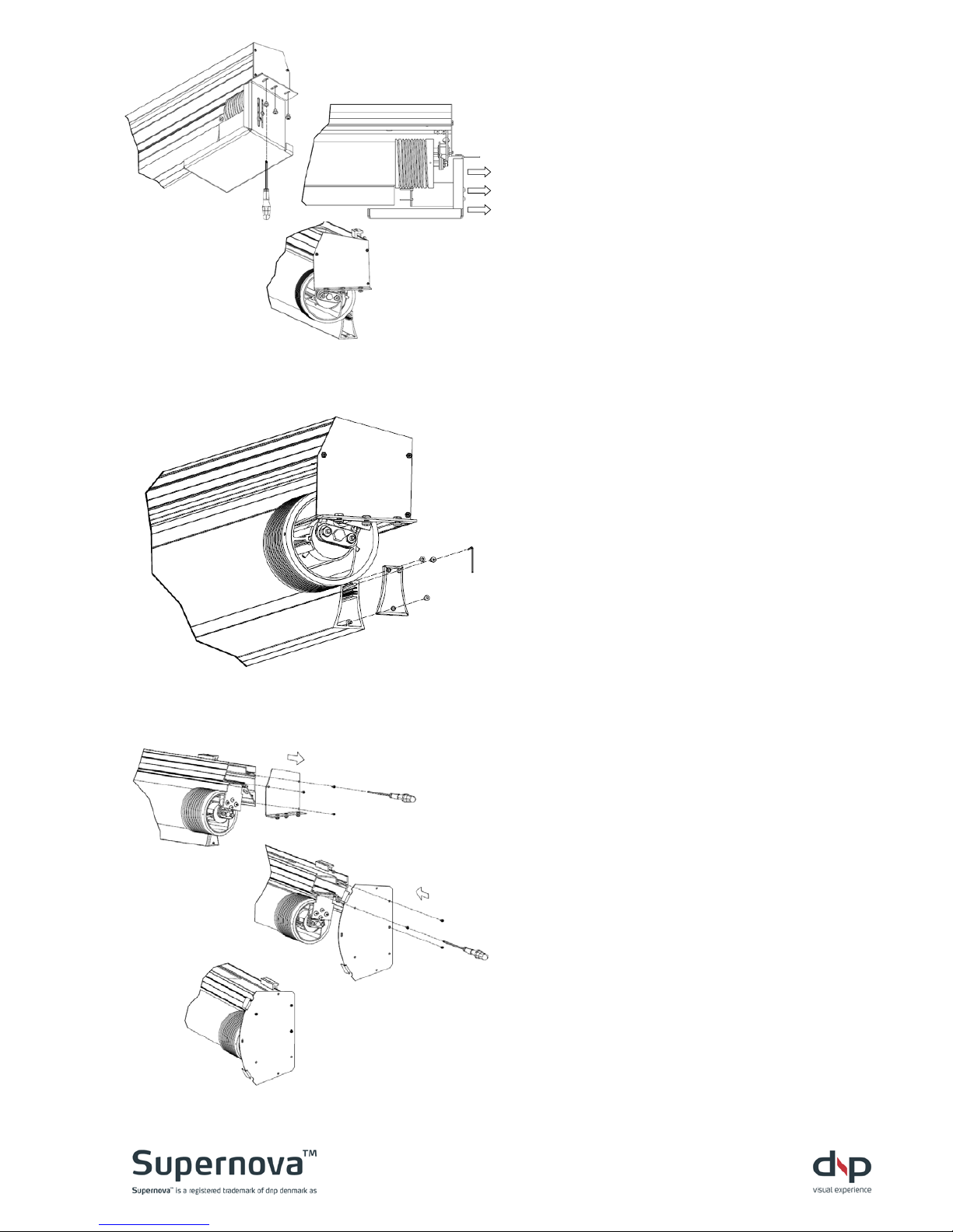
Removing fixtures
a. Remove connection screws from
shipping fixtures (1) and …
b. Carefully remove lower part of
shipping fixtures from ends of
screen assembly (2).
c. Upper part of shipping fixture
stays on master frame (3)
_____
E8
Mount end-caps
a. Unpack two end-caps and screws.
b. Attach end-caps to lower bar and
tighten the screws.
_____
E9
Replace shipping fixture
NOTE! Only for on-wall installation
a. Detach screws in upper par of
shipping fixture. Keep screws.
b. Unpack end-plates in box 2.
c. Re-use screws from above to
attach end-plates.
1
2
3
Page 12
Page 12
E10
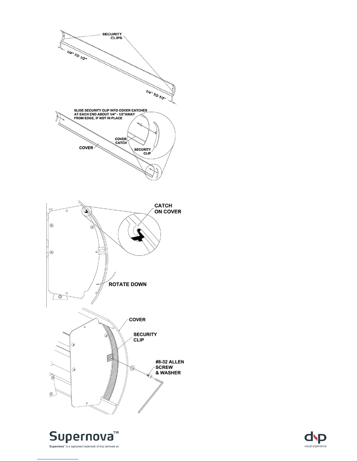
Attaching security clips
a. Slide security clips into the cover
catches at the ends of the cover.
b. Be sure ends of security clips are
seated in the cover catches.
c. Loos ely position security clips
near ends of cover.
_____
E11
Seating cover
a. Lift cover onto screen assembly.
b. Mate the catches on back of cover
to lip on top of screen assembly.
c. Rotat e cover down until it stops.
E12
Securing cover
a. Position security clips on outside
of screen assembly ends and …
b. Secure with #8-32 screws and
washers.
Page 13
Page 13
´
E13
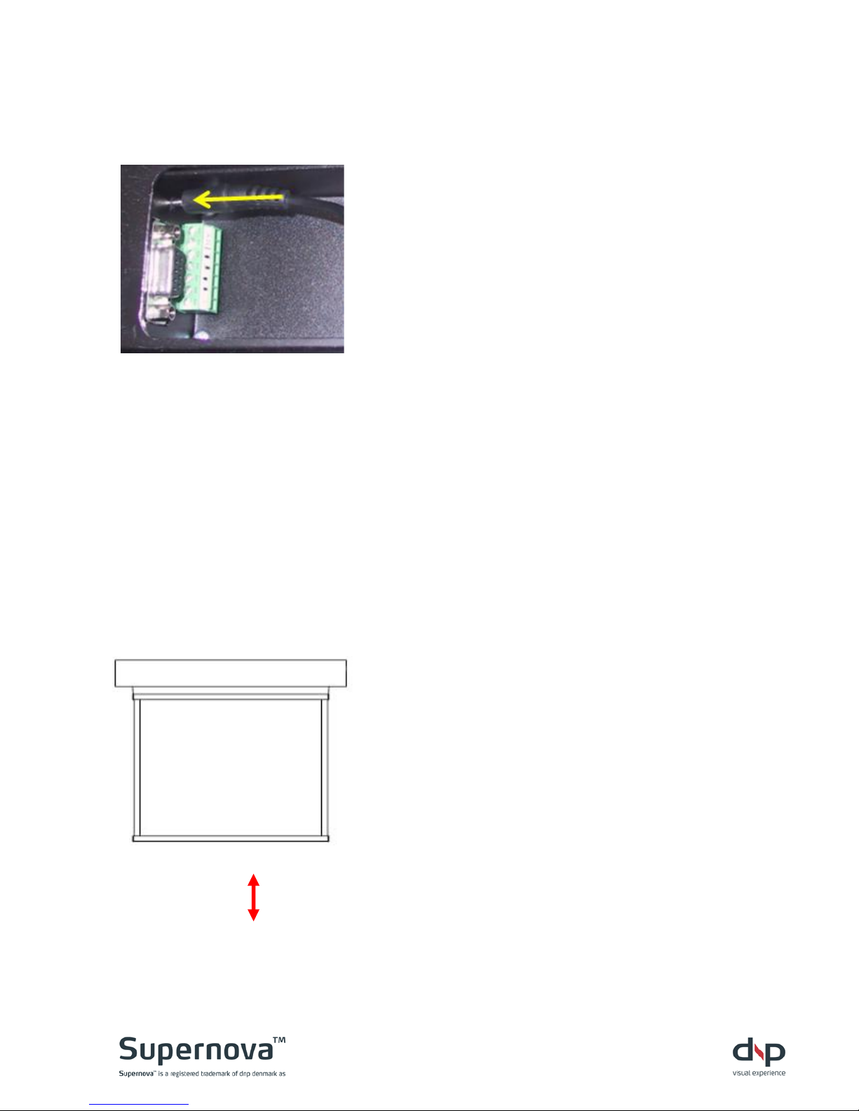
Powering up (Plug in)
a. Insert the plug of the IR receiver cable into
the mini-jack socket in the screen (located
next to the RS-232 socket). See photo left.
b. Place the infrared eye in the metal holder and
ensure that good visible contact to the remote
control can be obtained.
c. Plug the power cord into the screen- and wall
sockets. A green LED is lit when power is on
(positioned left of the green Phoenix plug)
d. See section G Remote control button
functionality for detailed information on the
remote control
e. Press the lower button [DOWN] on the
remote control to move the screen to the
factory set bottom stop position
See section F Setting new stop positions for
information on how to set a new bottom stop
position
f. Press the upper button [UP] on the remote
control to move the screen to the factory set
top stop position
E14
Checking smooth operation
a. Check extension and retraction of screen.
b. Ensure that screen retracts smoothly and
does not snag on any parts.
c. Ens ure that full screen extension operates
without hitting obstacles.
Page 14
Page 14
F Setting new stop positions
Top- and bottom stop positions are pre-set at the factory.
Do NOT change the top stop position!!!
High risk of damaging the screen If not done correctly.
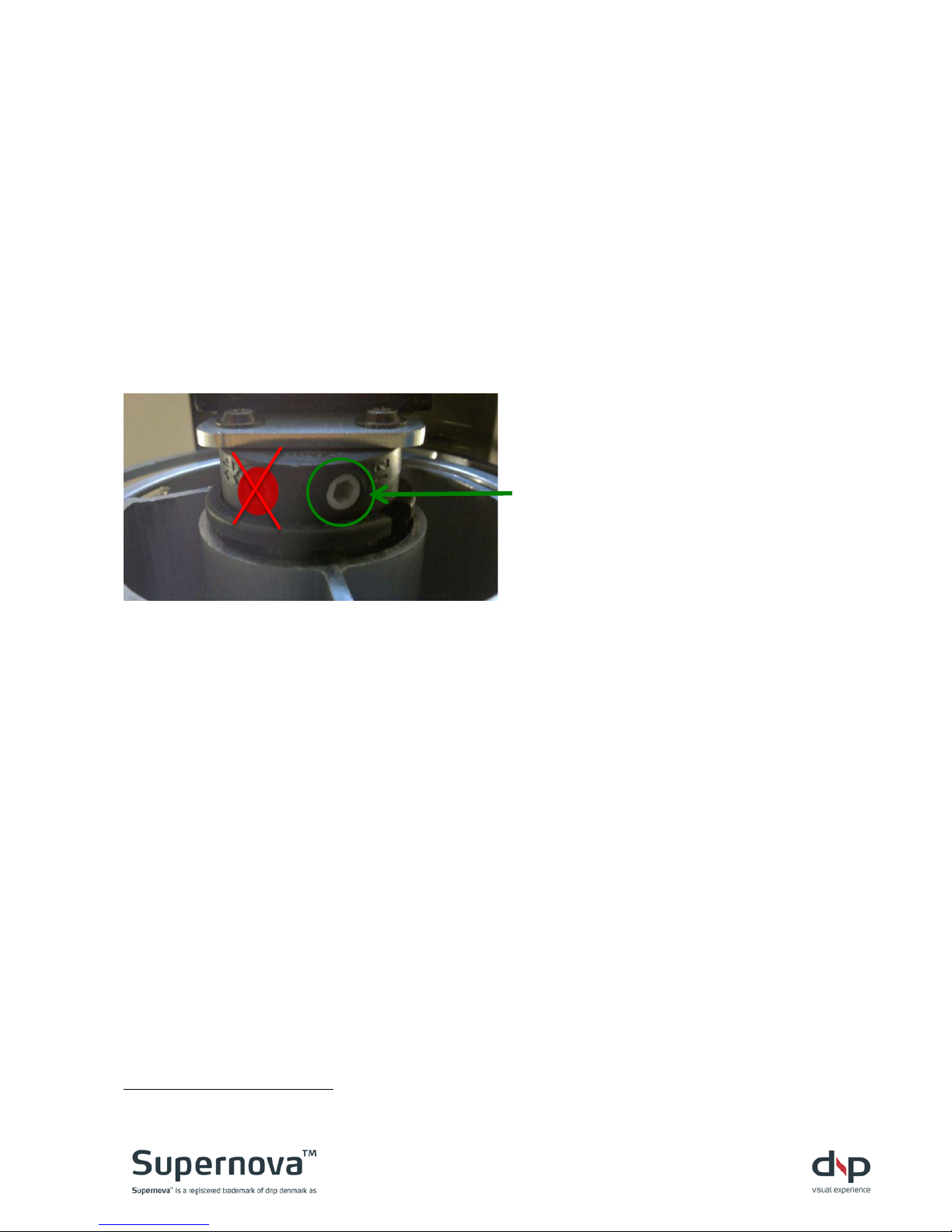
On the motor there are two hex-screws, marked 1 and 2, that are used to
manually adjust the stop p ositions .
Screw #1 is used to adjust the top stop position (sealed from factory
1
)
Screw #2 is used to adjust the bottom stop position
Adjustment screw #2 is
positioned to the right
(side view).
To set a new TOP position:
As highlighted above this is NOT recommended and will void the warranty.
NOTE! When the screen is up there must be space between the bottom bar
and the backside of the screen material and to the master frame. If the top
position is set too high, and the bottom bar is touching the screen material
and/or the master frame, permanent stress is applied to screen components
when the screen is up. This may lead to permanent damages to the screen
material and/or framing system This is NOT covered by the dnp warranty
1
Do not break seal. Bre aking seal would void the dnp warrant y.
Page 15
Page 15
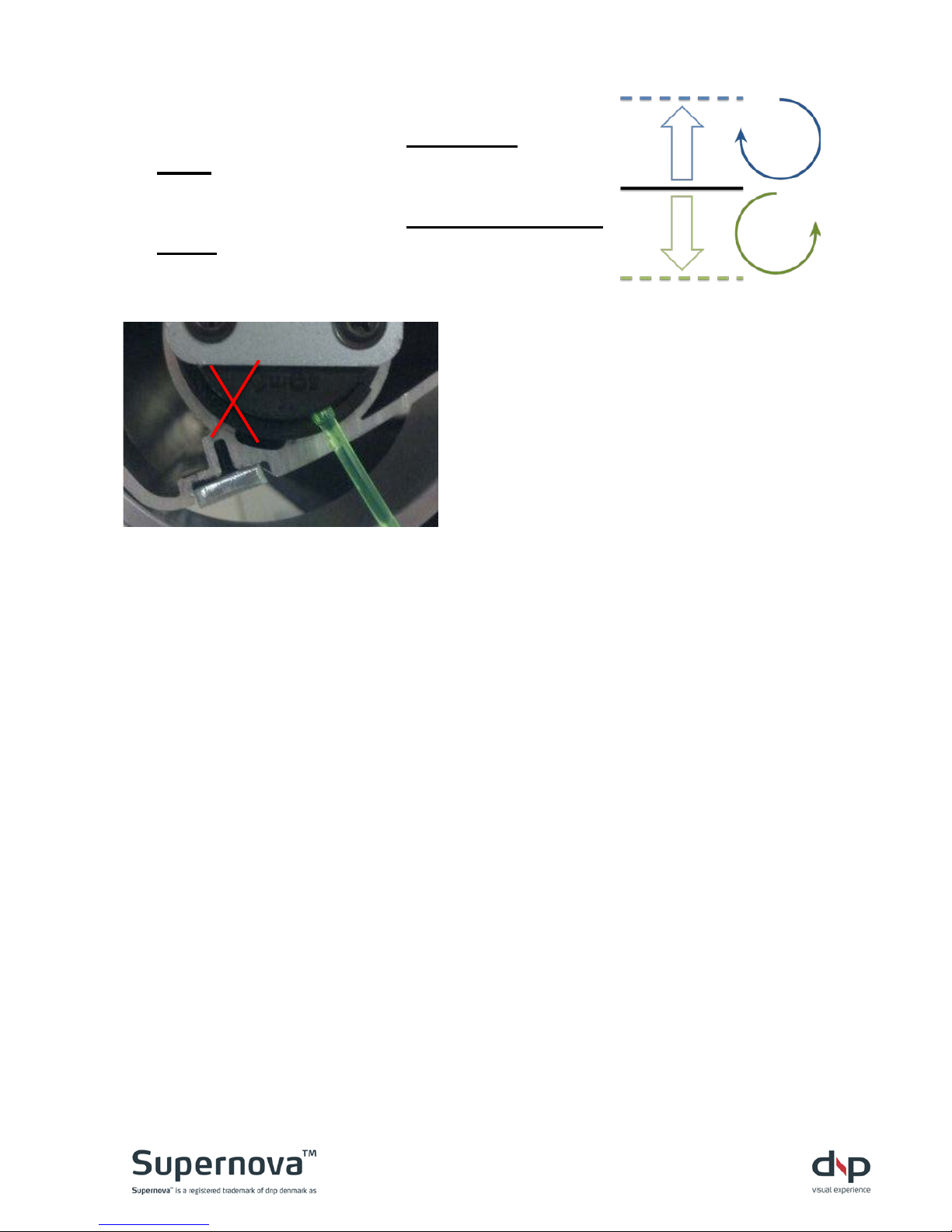
To set a new BOTTOM position:
Turn adjustment screw #2 clockwise
to raise the bottom stop position
Turn adjustment screw #2 counterclockwise
to lower the bottom stop position
One turn of the adjustment screw
will move the stop approximately 2”
CAUTION! Leave at least two revolutions of the steel wire on the helixes.
Otherwise there is risk of the lower part of the screen separating from the
helix/roller. This is NOT covered by the dnp warranty.
CAUTION! Be careful not to lower the screen too far. If the screen is
continuously lowered it will eventually reverse on the roller, which may lead to
permanent damage of screen components. This is NOT covered by the dnp
warranty
Page 16
Page 16
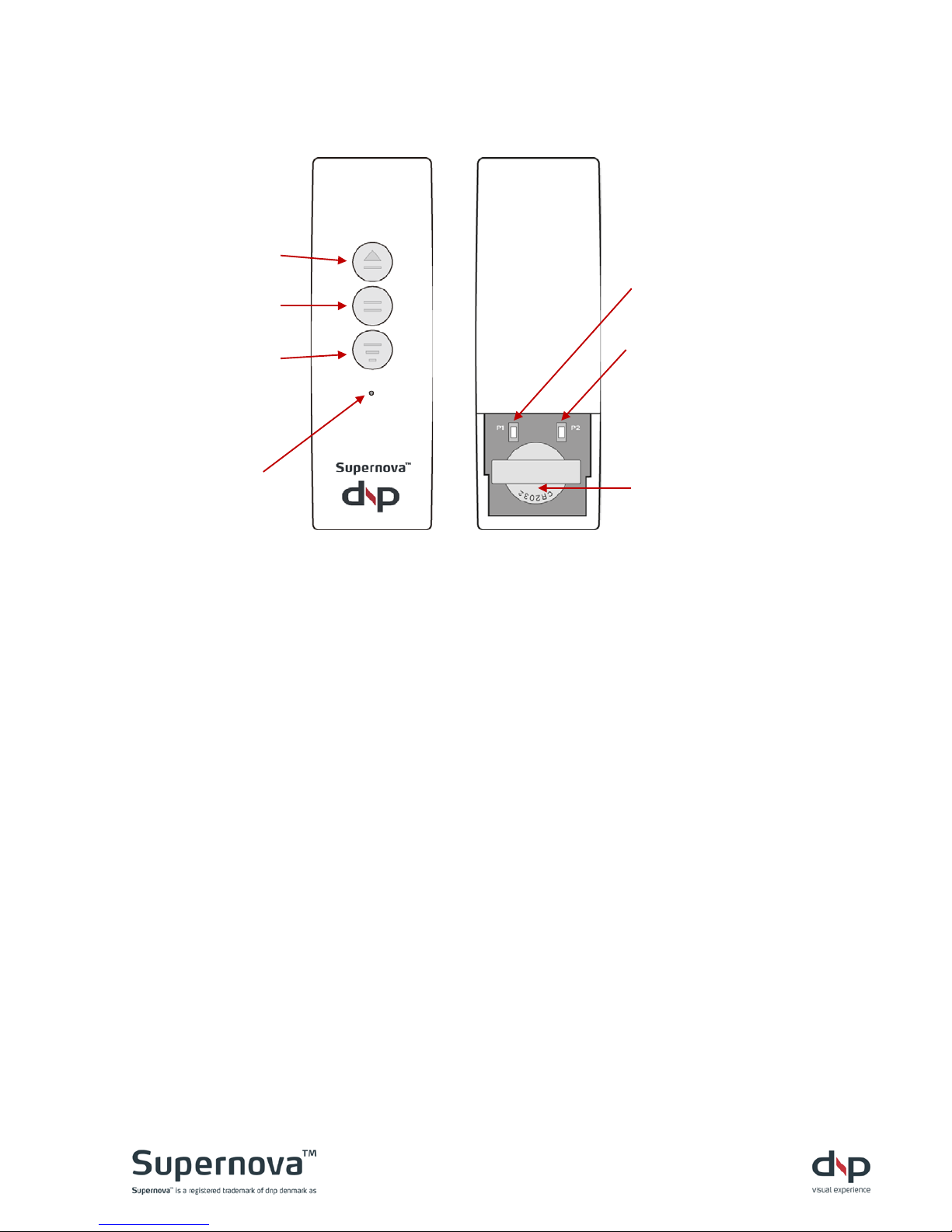
G Remote control button functionality
Front Rear
NOTE! Be aware when installing two screens close to each other or close to
other equipment using the same IR communication protocol. Commands may
activate other electronic components.
Batteries
3V CR2032 battery included. Remove battery cover and insert battery with + out.
Check that LED is lit when pressing a button. Rep
CAUTION!
Danger of explosion if battery is incorrectly replaced.
Replace only with the same or equivalent type.
Do not use re-chargeable batteries.
Batteries (battery pack or batteries installed) shall not be exposed to excessive heat such
as sunshine, fire or the like.
ATTENTION!
Danger d'explosion si la pile n’est pas remplacée correctement.
Ne remplacer que par le même type ou un type équivalent.
Ne pas utiliser de piles rechargeables
Les batteries (bloc de batteries ou batteries installées) ne doivent pas être exposées à une
chaleur excessive telle que celle du soleil, d’un feu ou d’origine similaire
.
[UP]
move screen to
top position
[STOP]
stop screen
in current position
[DOWN]
move
screen to bottom position
DIODE
lit when
button is pressed
[Stepwise UP]
step screen up
[Stepwise DOWN]
step screen down
Battery
3V CR2032
Page 17
Page 17
H Communication
IR remote control
See section G Remote control button functionality on how to operate the IR
remote control. The remote is using a special IR protocol. Conta ct dnp
denmark for more information.
Contact closure
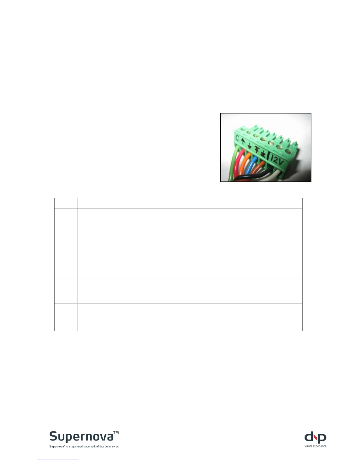
To operate the Supernova Flex through contact
closures, a pluggable terminal block connection
is available. The terminal block has seven
positions for wires.
For contact closure operation, the five terminals
on the left side of the terminal block are used.
The operation of the screen through this port is
as follows:
Label Name Description
C
Common Common wire, shorted to others for control.
Raise
Momentarily connect to common to raise the screen
incrementally. The screen will rise as long as this contact
remains shorted to common.
Lower
Momentarily connect to common to lower the screen
incrementally. The screen will lower as long as this contact
remains shorted to common.
Top
Momentarily connect to common to send the screen to the
preprogrammed top position. It is not necessary to continue
connecting to common after motion begins.
Bottom
Momentarily connect to common to send the screen to the
preprogrammed bottom position. It is not necessary to continue
connecting to common after motion begins.
12V-Trigger control
For low-voltage trigger operation the two terminals on the right side of the
terminal block are used. Applying 5V to 12V (AC or DC) to these two
terminals will cause the screen to lower to the bottom position; removal of the
voltage will cause the screen to return to the top position. Polarity is not
important (either polarity works for DC voltag e).
Page 18
Page 18
RS-232 serial control
Introduction
The interface is based on RS-232 using 115200 Baud, 8 databits, 1 start bit,
1 stop bit and no parity.
Protocol
The protocol is line-oriented. The controller expects single command lines
containing a command word - optionally followed by one or more parameters,
each separated by one or more spaces. Command lines must be terminated
by a single carriage return (ASCII code 13) and may be optionally followed by
a linefeed (ASCII code 10).
Command words are not case-sensitive. They may be abbreviated.
The controller will respond to command lines with a status message. In
response to some commands the controller may send multi line responses.
When powered up, the controller will send an initial welcome message, which
includes the serial number and the firmware version.
dnp denmark – Supernova Flex
Serial no. 123456. FW ver. 7.8.9
User commands
This section describes most common user commands in detail. Items
enclosed in square brackets are optional. For example, the command syntax
for moving the screen to the bottom stop position is:
B[ottom]
Possible command lines are
“B“ or “b“ or “BOTTOM“ or “bottom“
Status messages are sent by the controller in response to a command line:
“moving to bottom stop position”
Page 19
Page 19
b[ottom]
Moves the screen to the bottom stop position.
bottom
moving to bottom stop position
done
d[own]
Moves the screen o ne st ep down.
down
moving one step down
done
h[elp] or ?
Lists all available commands.
help
Command list follows:
B[ottom] : Move screen to bottom stop position
D[own] : Move screen one step down
H[elp] : List available commands
I[nfo] : Show system information
T[op] : Move screen to top position
U[p] : Move screen one step up
X : Immediately stop screen movement
? : List available commands
i[nfo]
Shows system information.
Info
dnp denmark – Supernova Flex
Serial no. 123456. F W ver. 7.8.9
t[op]
Moves the screen to the top stop position.
Top
moving to top stop position
done
u[p]
Moves the screen one step up.
Up
moving one step up
done
x
Immediately stops current screen movement.
x
stopped by user
Page 20
Page 20
I Troubleshooting
The screen will not move:
Check
Solution
Is the power cord connected?
Plug into screen and wall socket.
Is power on (is green LED lit)?
Turn on power
Is screen at top position?
Screen cannot move beyond top position. Move down.
Is screen at bottom position?
Screen cannot move beyond bottom position. Move up, or change
bottom stop position (see section F Setting new stop positions).
If low-voltage trigger is used:
- are connections OK?
- is signal correctly sent?
Connect wires correctly (see section H Communication)
May help to change to longer pulse-signal or change to permanent
on-signal
If contact closure is used:
- are connections OK?
- is relay working properly?
Connect wires correctly (see section H Communication)
Make sure that relay is short circuiting.
If RS-232 is used:
- is correct protocol used?
- is correct command used?
- is there an error message?
See section H Communication for communication protocol.
See section H Communication
for available commands.
Try resetting controller by power off and power on. If the error
message re-occurs contact place of purchase.
If IR remote control is used:
- is IR remote working?
- is battery correctly inserted?
- is visible contact to IR sensor OK?
Check that LED is lit when pressing buttons . Check that signal is
sent by looking through (mobile phone ) camera.
Ensure that battery is correctl y installed w ith + up/out
Re-position sensor or move any obstructions.
A number of failures (i.e. screen
overload) will automatically disable
the controller.
1) Disconnect and re-connect power.
2) Follow section E Mounting screen assembly
on how to start up
after power off.
Still not working?
Contact place of purchase.
Page 21
Page 21
J Cleaning
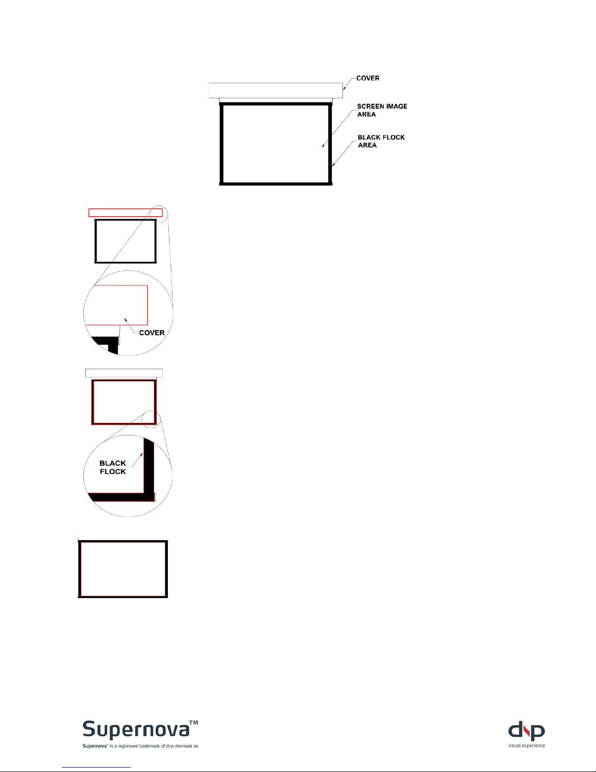
Cover / Chassis
Slightly dusty
Dust with a feather duster or
something similar. Light vacuum
cleaning is possible, but make
sure to use a fitting with bristles
that are not too soft but not hard
enough to scratch t he s ur face.
Dirty
Use a standard detergent for
household cleaning – never
harsh acidic or alkaline cleaners,
as they may stain the frame.
Take care to avoid scratching.
Dry with a lint-free cloth.
Black velvet area
Slightly dusty
Dust with a feather duster or
something similar.
Dirty
Clean with a gentle detergent
solution. Apply with a small
brush. We recommend a soft
toothbrush. Dry with a lint-free
cloth or with a hairdryer without
heat.
Screen image area
Slightly dusty
Dust with a feather duster or
something similar.
Dirty
Use an ordinary window cleaner
with ammonia or alcohol. Treat
the entire image area and clean
with a paint pad or lint-free cloth.
Apply gentle counter-pressure
on the opposite side.
Make sure the screen is
completely dry afterwards –
leave it down overnight to dry.
Page 22

Page 22
K Sales & delivery terms
1. SCOPE. Thes e sales and delivery terms apply to all quotations, orders, sales, and deliveries of
mechanical products more specific Supernova Flex, Supernova Epic, and Supernova Mobile from
dnp denmark as unless otherwise agreed in writing.
2. PRODUCT INFORMATION FROM DNP DENMARK A/S. Information in advertising materials,
folders, installation guidelines etc. on construction, materials, specifications, installation, and use of
dnp denmark's products is subject to change without notice. Such information is binding on dnp
denmark only if agreed in writing or confirmed by dnp denmark. dnp denmark reserves the right to
make changes to agreed specifications, instructions on installation and mounting if this is possible
without disadvantage to the customer.
3. PAYMENT. Payment shall be made by the customer at latest on the due date fixed in dnp
denmark's invoice. In case of late payment dnp may add interest on the sum owing at the rate of 2%
per running month from the due date. Unless otherwise agreed in writing, all deliver ie s will b e
made when dnp denmark has received payment from the customer.
4. DELIVERY. All deliveries from dnp denmark are ex works unless other terms of delivery are
agreed in writing. If so, the terms of delivery shall be interpreted and understood in accordance
with the Incoterms applicable as of the date of the agreement.
5. DELAY. The delivery date is fixed in accordance with dnp denmark's best estimate based on the
conditions applying as of the date of the agreement. Unless otherwise expressly agreed, a
postponement by dnp denmark of 30 days of the delivery date attributable to circumstances
relating to dnp denmark shall be deemed in all respects to be timely delivery, and the customer
shall not be entitled to terminate the agreement or invoke any of the breach of contract provisions
otherwise applicable as a consequence of the postponement.
If the order includes various products confirmed for delivery at the same time, dnp denmark shall
be entitled to deliver the products which are ready for delivery at the agreed time and to postpone
delivery of the other products included in the agreement against payment of fr eight costs
associated with such delivery by dnp. In such event the customer shall not be entitled to canc el the
agreement or to claim breach of contract as a consequence of the delay.
If dnp denmark is prevented from fulfilling the agreement or if fulfilment of the agreement would be
unreasonably burdensome by reason of extraneous circumstances (force majeure) such as strike,
fire , war, requisitioning of operating equipment, sequestration, currency restrictions, civil
disturbance or unrest, or missing or delayed deliveries from subcontractors attributable to the
above circumstances, the delivery time shall be postponed by the duration of the disturbance and
none of the parties shall be entitled to claim against each other.
dnp denmark will advise the customer of changes to the delivery date with out undue delay in
accordance with the above provisions and as far as possible give a new delivery date.
6. DEFECTS AND DEFICIENCIES. Immediately on receipt of the delivery the customer is required
to examine the delivery in accordance with normal business practices.
If the customer wishes to claim a defect or deficiency, dnp denmark shall be advised immediately
in writing. The customer shall otherwise forfeit any claim against dnp denmark.
dnp denmark may rectify the deficiency by replacement of product parts, repair or redelivery.
Freight costs in connection with return of the delivery to dnp denmark will be refunded to the
customer if dnp denmark can accept that the delivery was defective.
If defects or deficiencies have not been claimed against dnp denmark within (24) months of the
delivery, the customer shall not be entitled to make subsequent claim.
Page 23

Page 23
dnp denmark shall not be liable for defects and deficiencies attributable to circumstances outside
of dnp’s control or of no concern to dnp including
° Inadequate training of the customer's personnel
° Failure to observe dnp denmark's instructions
° Faults arising from normal use
° Damage arising during the purchaser's transport of the delivery.
7. WARRANTY. dnp denmark as warrants the product against defects in material and
workmanship under normal use in accordance with dnp denmark’s instructions on installation, use,
maintenance, and repair etc. dnp denmark as will for a period of (1) year from date of invoice
without extra cost for the customer make replacements, repair or redelivery of the parts with
defects due to defective materials or workmanship. Replacement, repair, or redelivery is made by
dnp denmark as at its option and the warranty hereof is valid f or t he remaining period of the
original warranty period.
To obtain warranty service the product serial number or other identification according to the
agreement may not be removed or defaced. Furthermore, this warranty does not apply to damages
or defects caused by normal use, accidents, wear and tear, reckless use of the product, use of the
product for other than intended purposes and/or use not complying with dnp denmark’s instructions
on correct use, maintenance, handling, or installation. Claims during the warranty period also
require that the product is used according to the current local technical or security standards, and
no unauthorised or non-approved accessories have been used, as well as any modificat ions and
changes in the product regardless of the reason and regardless if the adjustment has been
correctly made. Additionally warranty claims are conditioned by no use of unauthorised software or
virus and the warrant does not apply to damage caused by force majeur e among others fire, flood
etc.
The warranty does only apply product defects in the above stated. The guarantee does not cover
financial losses, direct or indirect losses or consequential damages.
8. PRODUCT LIABILITY. dnp denmark is liable for damage or injury to person only if documentary
evidence can be provided that the damage is attributable to error or negligence on the part of dnp
denmark. dnp denmark shall not be liable for damage to property or chattels belonging to the
purchaser or others unless the damage is due to gross negligence on the part of dnp denmark. dnp
denmark's liability may in no case exceed DKK five (5) million. dnp denmark can in no event be
held liable for operating loss, loss of profit or any other indirect losses.
If product liability is ascribed to dnp denmark by third party, the customer shall indemnify dnp
denmark to the limit of dnp denmark's liability under this provision.
9. LIMITATION OF LIABILITY. The customer may in no event claim compensation for operating
loss, loss of profit or other indirect losses in cases of delays, defects or deficiencies, irrespective of
whether the delay, defect or the deficiency may be attributable to dnp denmark.
The customer may only claim a proportionate rebate in the purchase sum or compensation for the
customer's direct documented loss if the delay or the deficiency is attributable to gross negligence
on the part of dnp denmark.
10. DISPUTES AND JURISDICTION. Unless otherwise agreed in writing, any dispute between the
parties concerning the agreement shall be settled by arbitration in Copenhagen, Denmark, at the
Danish Institute for Arbitration, det Danske Voldgiftsinstitut, in accordance with the rules for
processing of cases at the General Arbitration Court in Denmark, "Regler for behandling af sager
ved Det Danske Voldgiftsinstitut". Danish law shall apply.
Page 24
Page 24
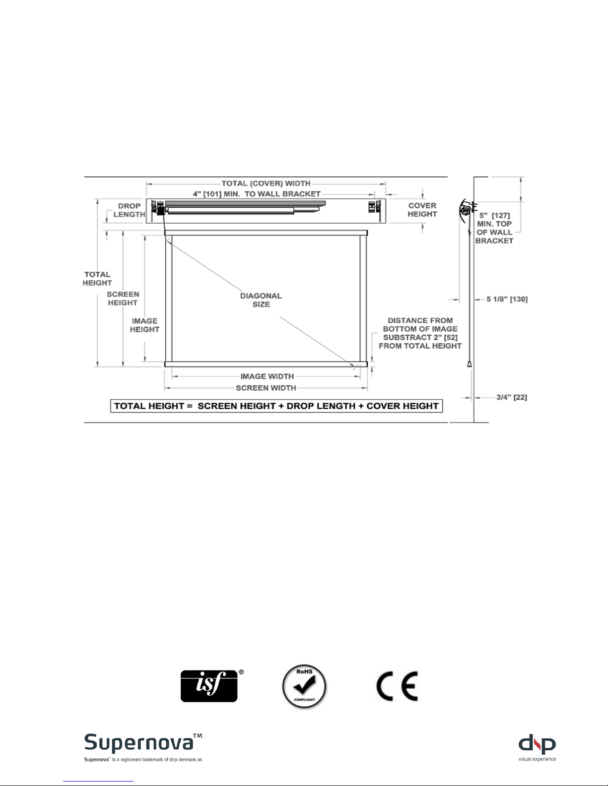
L Planning guide
Use below information and size specifications to determine the placement of
the screen and the wall brackets.
NOTE! See the Supernova Flex datasheet for screen specifications and
dimensions for your size of screen.
www.dnp-screens.com
dnp denmark as – Skruegangen 2 – 2690 Karlslunde – Denmark
Tel: +45 46 16 51 00 – Fax: +45 46 16 52 00 – [email protected]
US hotline: +1 (619) 600 2892
Rev. 3.01
 Loading...