

Page 1
> dnp | A | 3000 | HD | S
> dnp
| A | 3000 | HD | I
w
w
w
.dnp-
la
s
e.com
Page 2
2
Table of Contents ............................2
Usage Notice ...................................3
Safety Information ...............................3
Precautions .........................................4
Introduction ......................................6
Package Overview ..............................6
Product Overview ...............................7
Main Unit ..............................................7
Control Panel .......................................8
Input/Output Connections ....................9
Remote Control ..................................10
Installation ..................................... 11
Connecting the Projector ..................11
Connect to Computer/Notebook ........ 11
Connect to Video Sources .................12
Powering the Projector On / Off ........13
Powering On the Projector .................13
Powering Off the Projector .................14
Warning Indicator ...............................14
Adjusting the Projected Image ..........15
Adjusting the Projector’s Height ........15
Adjusting the Projector’s Focus .........16
Adjusting Projection Image Size
(Diagonal) ..........................................17
User Controls ................................18
Control Panel & Remote Control ......18
Control Panel .....................................18
Remote Control ..................................19
On-screen Display Menus ................21
How to operate .................................21
Picture ................................................22
Screen ...............................................24
Settings ..............................................26
Volume ...............................................28
Options ..............................................29
Options | Laser Settings ....................31
3D ......................................................32
Blending mode ...................................33
Interactive ..........................................34
LAN ....................................................44
Multimedia .....................................53
EZView..............................................53
Accessing Multimedia Files ..............57
How to access Multimedia mode .......57
Appendices ....................................64
Installing and Cleaning the Optional
Dust Filter .........................................64
Compatibility Modes .........................65
VGA Analog .......................................65
HDMI Digital .......................................67
RS232 Commands and Protocol
Function List .....................................69
RS232 Port Settings ..........................69
RS232 Signals Connection ................69
Commands Set List ...........................70
Crestron ............................................73
Ceiling Mount Installation ..................76
T rouble-shooting ...............................77
Regulation & Safety Notices .............83
Table of Contents
Page 3
3
Usage Notice
Safety Information
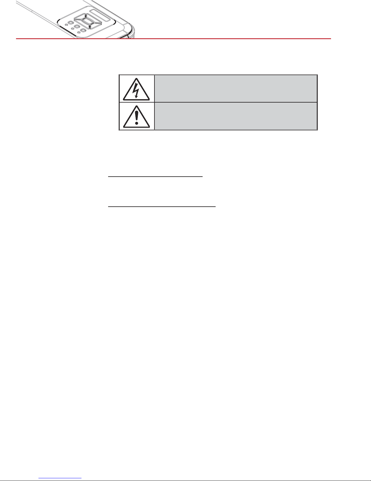
The lightning flash with arrow head within an equilateral triangle is
intended to alert the user to the presence of uninsulated “dangerous
voltage” within the product’s enclosure that may be of sufficient
magnitude to constitute a risk of electric shock to persons.
The exclamation point within an equilateral triangle is intended to alert
the user to the presence of important operating and maintenance
(servicing) instructions in the literature accompanying the appliance.
WARNING: TO REDUCE THE RISK OF FIRE OR ELECTRIC SHOCK, DO NOT
EXPOSE THIS APPLIANCE TO RAIN OR MOISTURE. DANGEROUS HIGH
VOLTAGES ARE PRESENT INSIDE THE ENCLOSURE. DO NOT OPEN THE
CABINET. REFER SERVICING TO QUALIFIED PERSONNEL ONLY.
Class B emissions limits
This Class B digital apparatus meets all requirements of the Canadian
Interference-Causing Equipment Regulations.
Important Safety Instruction
1. Do not block any ventilation openings. To ensure reliable operation of
the projector and to protect from over heating, it is recommended to
install the projector in a location that does not block ventilation. As an
example, do not place the projector on a crowded coffee table, sofa,
bed, etc. Do not put the projector in an enclosure such as a book case
or a cabinet that restricts air flow.
2. Do not use the projector near water or moisture. To reduce the risk
of fire and/or electric shock, do not expose the projector to rain or
moisture.
3. Do not install near heat sources such as radiators, heaters, stoves or
any other apparatus such as amplifiers that emits heat.
4. Clean only with dry cloth.
5. Only use attachments/accessories specified by the manufacturer.
6. Do not use the unit if it has been physically damaged or abused.
Physical damage/abuse would be (but not limited to):
> Unit has been dropped.
> Power supply cord or plug has been damaged.
> Liquid has been spilled on to the projector.
> Projector has been exposed to rain or moisture.
> Something has fallen in the projector or something is loose inside.
Do not attempt to service the unit yourself. Opening or removing covers
may expose you to dangerous voltages or other hazards.
7. Do not let objects or liquids enter the projector. They may touch
dangerous voltage points and short out parts that could result in fire or
electric shock.
8. See projector enclosure for safety related markings.
9. The unit should only be repaired by appropriate service personnel.
Page 4
4
Usage Notice
Precautions
Please follow all warnings, precautions and
maintenance as recommended in this user’s
guide.
> Warning- Do not look into the projector’s lens when the lamp is
on. The bright light may hurt and damage your eyes.
> Warning- To reduce the risk of fire or electric shock, do not ex-
pose this projector to rain or moisture.
> Warning- Please do not open or disassemble the projector as this
may cause electric shock.
Page 5
5
Usage Notice
Do:
> Turn off and unplug the power plug from the AC outlet before
cleaning the product.
> Use a soft dry cloth with mild detergent to clean the display
housing.
> Disconnect the power plug from AC outlet if the product is
not being used for a long period of time.
Do not:
> Block the slots and openings on the unit provided for
ventilation.
> Use abrasive cleaners, waxes or solvents to clean the unit.
> Use under the following conditions:
- In extremely hot, cold or humid environments.
> Sea level to 6000 feet
Extremely hot: > 35°C
Extremely cool: < 5°C
> 6000 feet above
Extremely hot: > 30°C
Extremely cool: < 5°C
> Extremely humid: > 70% R.H. (Relative Humidity)
-
In areas susceptible to excessive dust and dirt.
- Near any appliance generating a strong magnetic field.
- In direct sunlight.
Page 6
6
Introduction
> Some regions
may have
different
accessories.
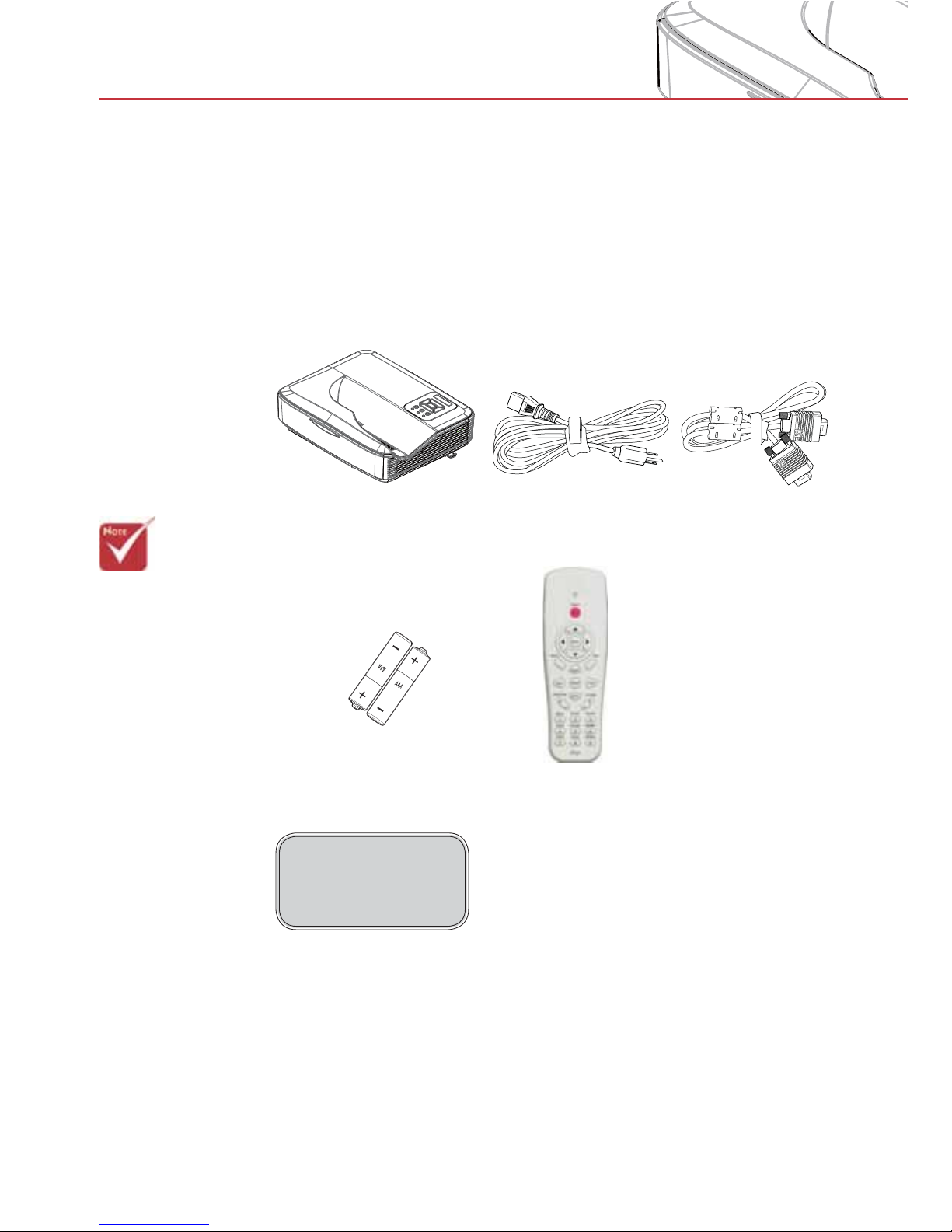
Power Cord
Package Overview
Unpack and inspect the box contents to ensure
all parts listed below are in the box. If something
is missing, please contact your nearest customer
service center.
Projector
VGA Cable
Documentation :
User’s Manual
2 × AAA Batteries
IR Remote Control
Page 7
7
Introduction
Product Overview
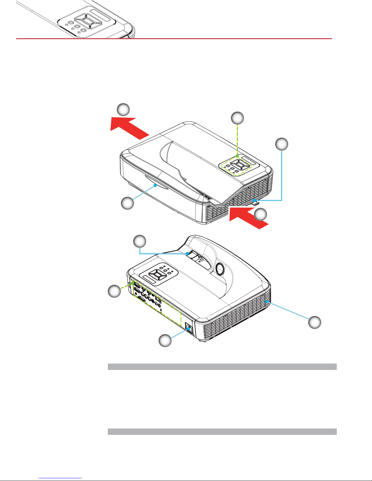
Main Unit
1. Control Panel
2. Focus Switch
3. Ventilation (inlet)
4. IR Receiver
5. Ventilation (outlet)
6. Speaker
7. Power Socket
8. Input / Output
Connections
9. Lens
6
7
8
4
2
5
3
1
9
Page 8
8
Introduction
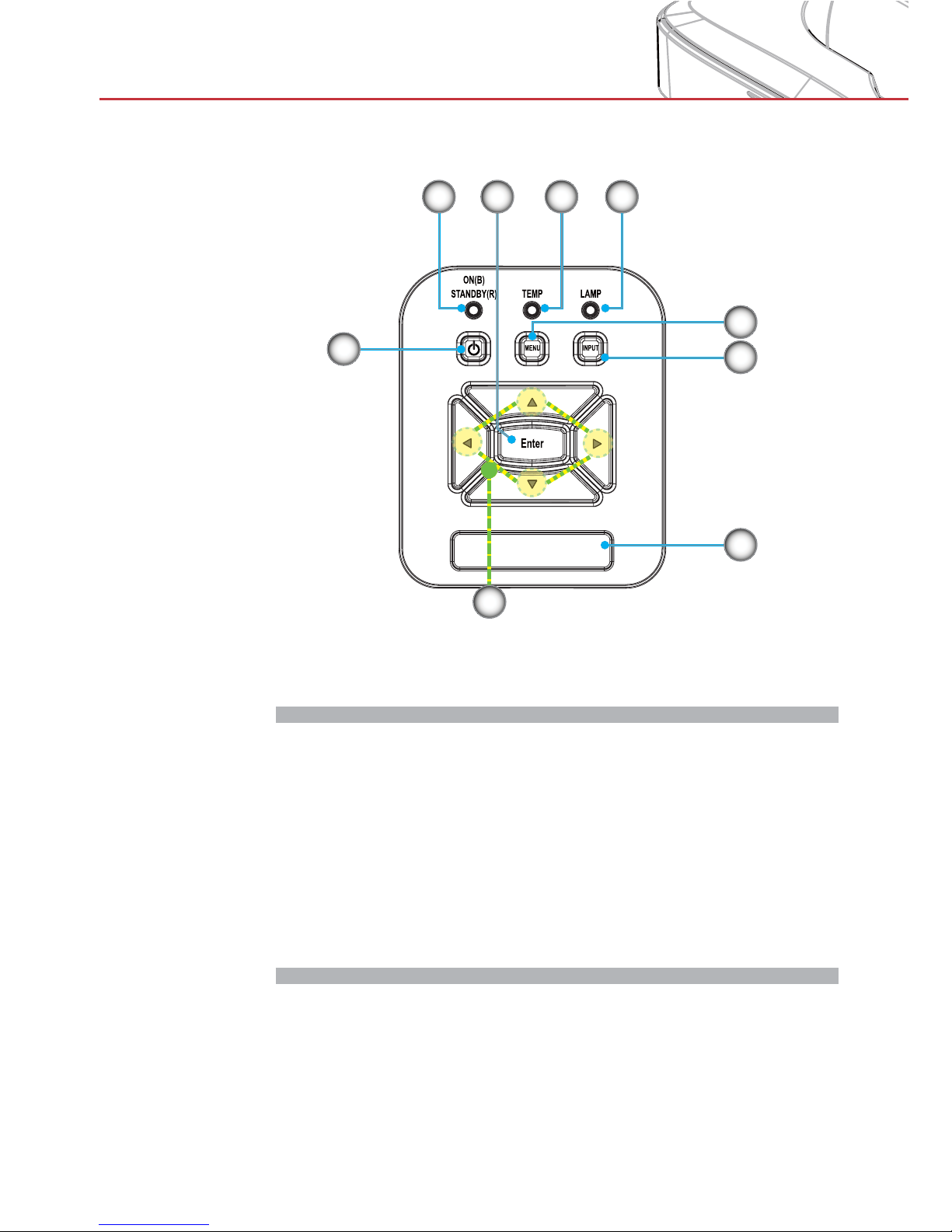
Control Panel
1. Power LED
2. Enter
3. Temp LED
4. Lamp LED
5. Menu
6. Input
7. Four Directional Select Keys
8. Power/Standby button
9. IR Receiver
3
6
9
8
7
21 4
5
Page 9
9
Introduction
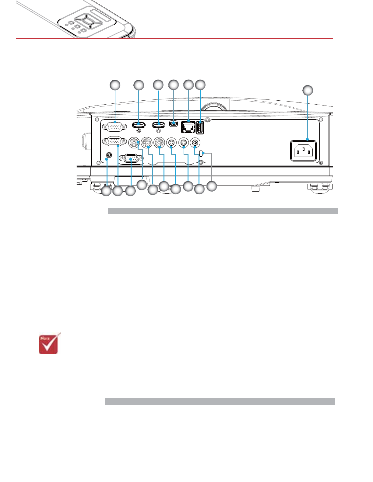
Input/Output Connections
> Monitor loop
through only
support in VGA1In/YPbPr.
VGA1-In/YPbPr Connector 1.
(PC Analog Signal/Component Video Input/HDTV/YPbPr)
HDMI2 Input Connector 2.
HDMI1 Input Connector 3.
USB Connector (Connect to PC for Remote Mouse 4.
function)
RJ45 connector (Optional)5.
USB Type A Connector (Optional)6.
Power Socket7.
Interactive Connector (3.5 mm mini jack, Optional)8.
VGA-Out/VGA2-In Connector9.
RS-232 Connector (9-pin DIN Type)10.
Composite Video Input Connector11.
Composite Audio Input (right) Connector 12.
Composite Audio Input (left) Connector 13.
Audio Output Connector (3.5mm mini jack) 14.
Audio Input Connector (3.5mm mini jack) 15.
Audio Input Connector (microphone) 16.
Kensington17.
TM
Lock Port
7
1 2
4
10
14
53
11
12
16
869
13 15
17
Page 10
10
Introduction
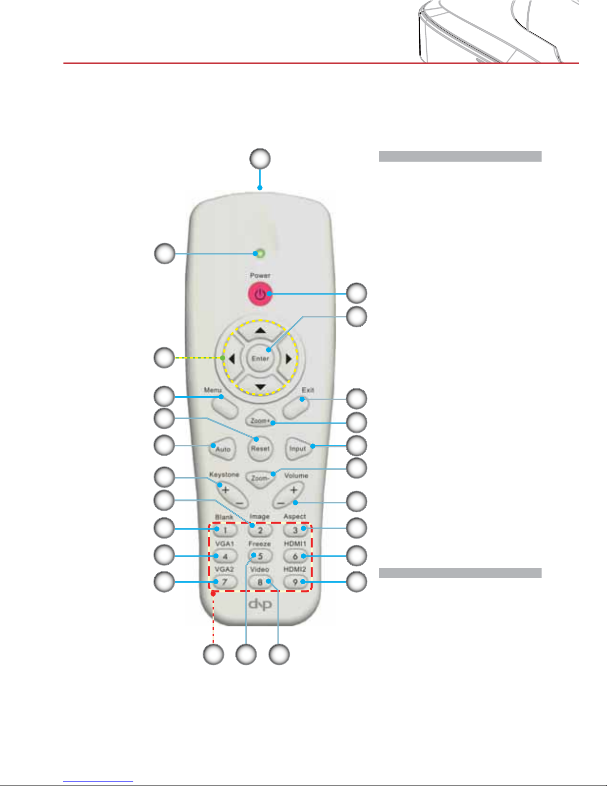
Remote Control
1. Infrared transmitter
2. LED Indicator
3. Power On/Off
4. OK
5. Four Directional
Select Keys
6. Menu
7. Exit
8. Zoom in
9. Reset
10. Auto
11. Source
12. Zoom out
13. Volume +/-
14. Keystone +/-
15. Image
16. Black screen
17. Aspect ratio
18. VGA1
19. HDMI1
20. VGA2
21. HDMI2
22. Video
23. Screen freeze
24. Numbered keypad
1
17
2223
20
18
16
9
15
13
21
24
2
11
14
10
7
12
6
5
3
4
8
19
Page 11
11
Installation
Connecting the Projector
> Some regions
may have different
accessories.
> (*) Optional
accessory
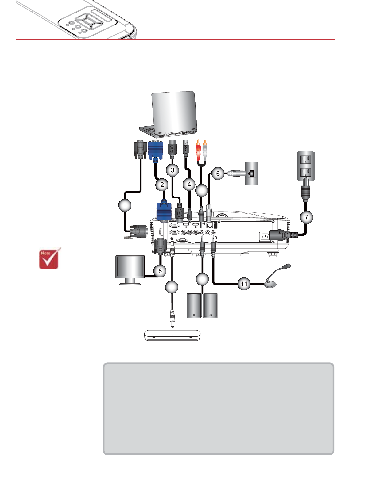
Connect to Computer/Notebook
E62405SP
R
MOLEX
1
5
10
9
Audio Output
Microphone
External
Display
Router / Network Switch
1................................................................................................*RS232 Cable
2.....................................................................................................VGA Cable
3..................................................................................................*HDMI Cable
4....................................................................................................*USB Cable
5......................................................................................... *Audio Cable/RCA
6.................................................................................................. *RJ45 Cable
7....................................................................................................Power Cord
8........................................................................................*VGA Output Cable
9............................................................................................*DC to DC Cable
10....................................................................................*Audio Output Cable
11 .......................................................................................*Audio Input Cable
Page 12

12
Installation
E62405SP
R
1
5
6
4
7
3
2
8
Connect to Video Sources
1................................................*15-Pin to 3 RCA Component/HDTV Adaptor
2..................................................................................................*HDMI Cable
3......................................................................................... *Audio Cable/RCA
4..................................................................................................*Audio Cable
5....................................................................................................Power Cord
6................................................................................*Composite Video Cable
7......................................................................................... *Audio Cable/RCA
8.........................................................................................*Audio Input Cable
> Some regions
may have different
accessories.
> (*) Optional
accessory
Composite Video Output
DVD Player, Set-top Box,
HDTV receiver
Microphone
Audio Output
Page 13

13
Installation
Powering the Projector On / Off
> Turn on the
projector first and
then select the
signal sources.
Powering On the Projector
1. Securely connect the power cord and signal cable. When
connected, the POWER/STANDBY LED will turn Orange.
2. Turn on the lamp by pressing “
” button either on the projec-
tor or on the remote. At this moment, the POWER/STANDBY
LED will now turn Blue.
The startup screen will display in approximately 10 seconds.
The first time you use the projector, you will be asked to
select the preferred language and power saving mode.
3. Turn on and connect the source that you want to display
on the screen (computer, notebook, video player, etc). The
projector will detect the source automatically. If not, push
menu button and go to “OPTIONS”.
Make sure that the “Source Lock” has been set to “Off”.
>If you connect multiple sources at the same time, press the
“INPUT” button on the control panel or direct source keys on
the remote control to switch between inputs.
>When the power
mode is in standby
mode (power consumption < 0.5W),
the VGA output/
input and audio
will be deactivated
when the projector
is in standby.
POWER/STANDBY
1
Page 14
14
Installation
>
Contact the
nearest service
center if the
projector displays
these symptoms.
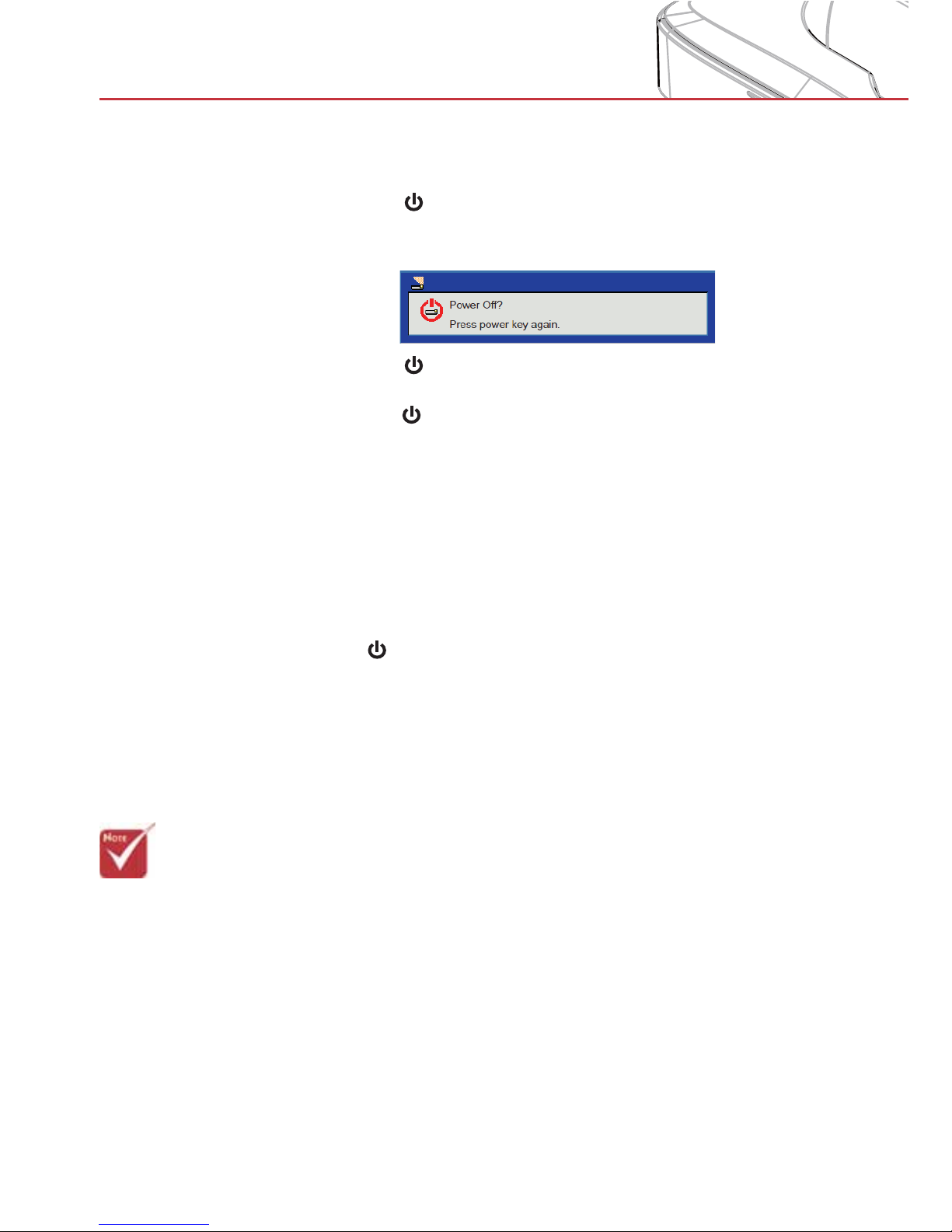
Powering Off the Projector
1. Press the “ ” button on the remote control or
on the control panel to turn off the projector.
The following message will be displayed on the screen.
Press the “ ” button again to confirm otherwise the
message will disappear after 10 seconds. When you
press the “ ” button for the second time, the fan will start
cooling the system and will shut down.
2. The cooling fans continue to operate for about 4 seconds
for cooling cycle and the POWER/STANDBY LED will
flash Orange. When the POWER/STANDBY LED lights
solid Orange, the projector has entered standby mode.
If you wish to turn the projector back on, you must wait
until the projector has completed the cooling cycle and
has entered standby mode. Once in standby mode, simply
press “
” button to restart the projector.
3. Disconnect the power cord from the electrical outlet and
the projector.
Warning Indicator
When the warning indicators (see below) come on,
the projector will automatically shutdown:
> “LAMP” LED indicator is lit red and if “POWER/STANDBY”
indicator flashes amber.
> “TEMP” LED indicator is lit red, this indicates the projector
has overheated. Under normal conditions, the projector
can be switched back on.
> “TEMP” LED indicator flashes red and if “POWER/
STANDBY” indicator flashes amber.
Unplug the power cord from the projector, wait for 30 seconds and try again. If the warning indicator light up again,
please contact your nearest service center for assistance.
Page 15
15
Installation
Adjusting the Projected Image
Adjusting the Projector’s Height
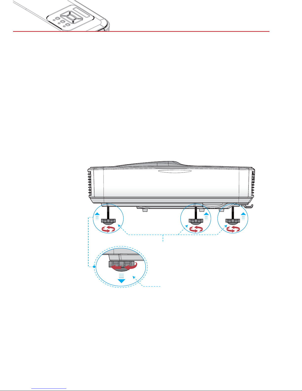
The projector is equipped with adjustable feet for adjusting the image height position.
1. Locate the foot you want to adjust on the underside of the
projector.
2. Turn the adjustable foot counter-clockwise to move it
outwards or clockwise to move it inwards. Repeat with the
remaining feet as needed.
Adjustable Feet
Adjustable Ring
Page 16
16
Installation
Adjusting the Projector’s Focus
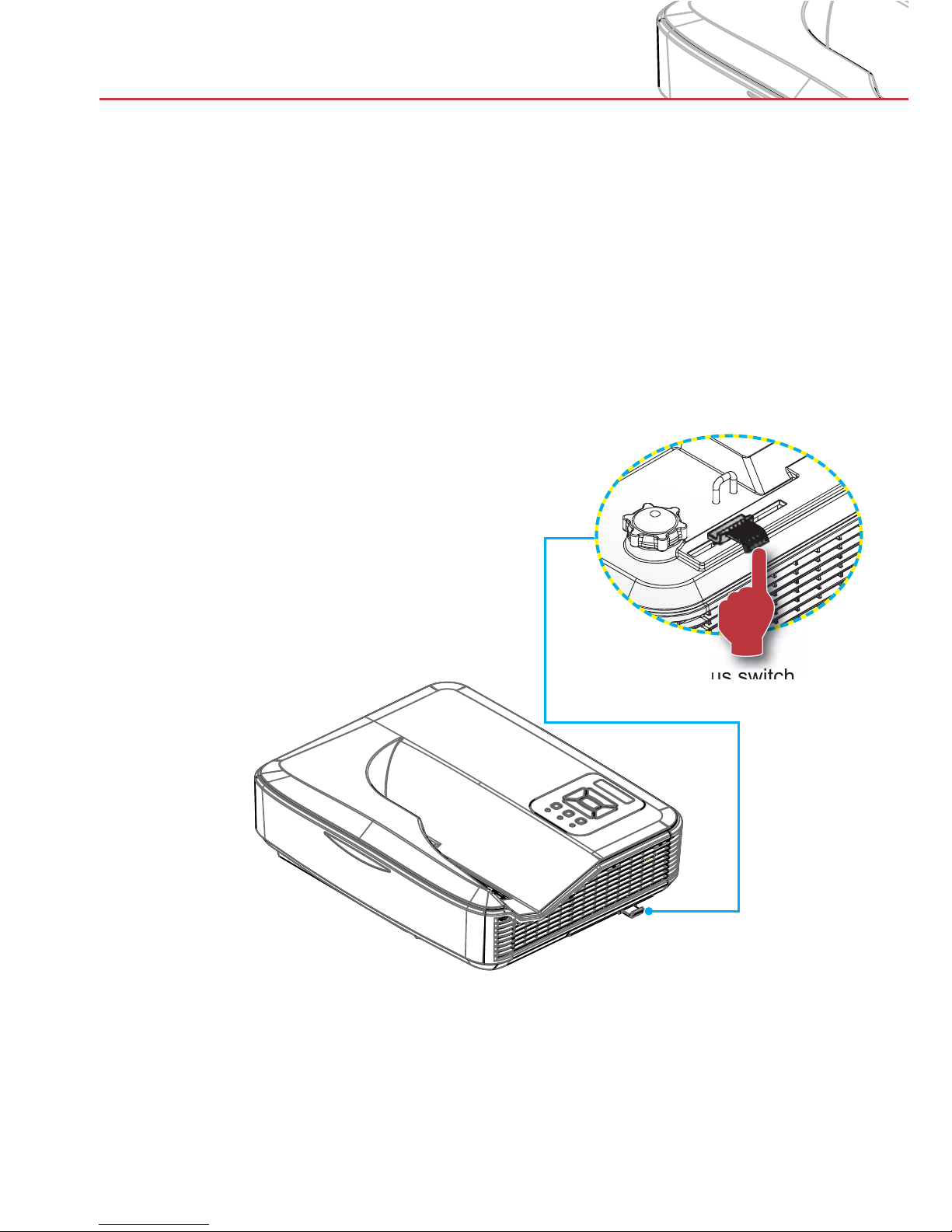
To focus the image, slide the focus switch to left/right until the
image is clear.
>
The projector will focus at distances (lens to wall) from
1.59~1.87 feet (0.49~0.57 meters)
Focus switch
Page 17
17
Installation
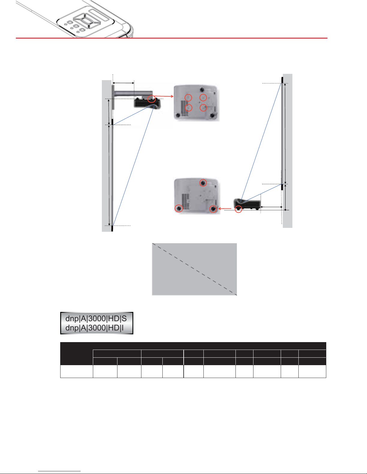
Adjusting Projection Image Size (Diagonal)
dnp|A|3000|HD|S
dnp|A|3000|HD|I
Diagonal
size (inches)
Image size Projection distance Offset
mm inches mm inches mm inches mm inches
W H W H D D Hd1 Hd1 Hd2 Hd2
100 2214 1245 87.2 49.0 305 12.0 322 12.7 325 12.8
> This table is for user’s reference only.
Width
Height
Diagonal
! "
! "
Page 18
18
User Controls
Control Panel
Control Panel & Remote Control
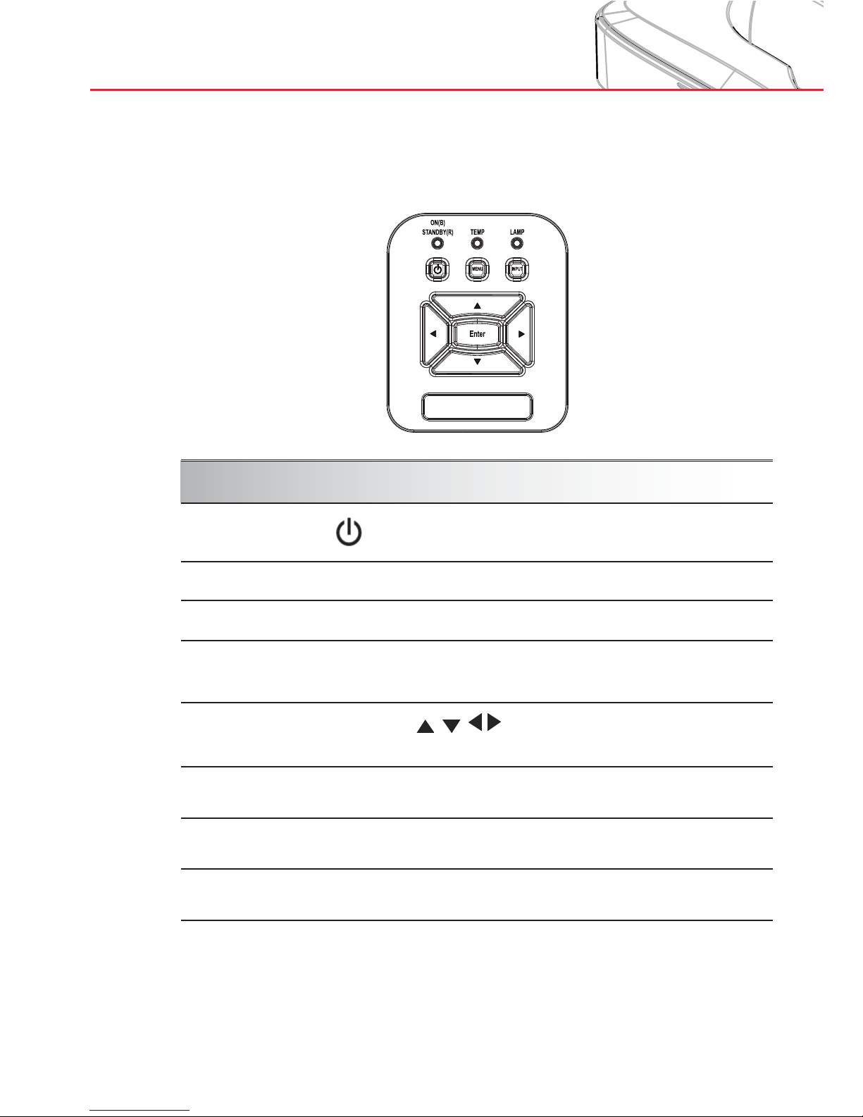
Using the Control Panel
POWER
Refer to the “Power On/Off the Projector”
section on pages 13-14.
Enter Press “Enter” to confirm your item selection.
INPUT Press “INPUT” to select an input signal.
MENU
Press “MENU” to launch the on-screen display
(OSD) menu. To exit OSD, press “MENU” again.
Four Directional
Select Keys
Use
to select items or make
adjustments to your selection.
LAMP LED
Refer to the LED indicator of the projector light
source status.
TEMP LED
Refer to the LED indicator of the projector
temperature status.
ON/STANDBY
LED
Refer to the LED indicator of the projector
power status.
Page 19
19
User Controls
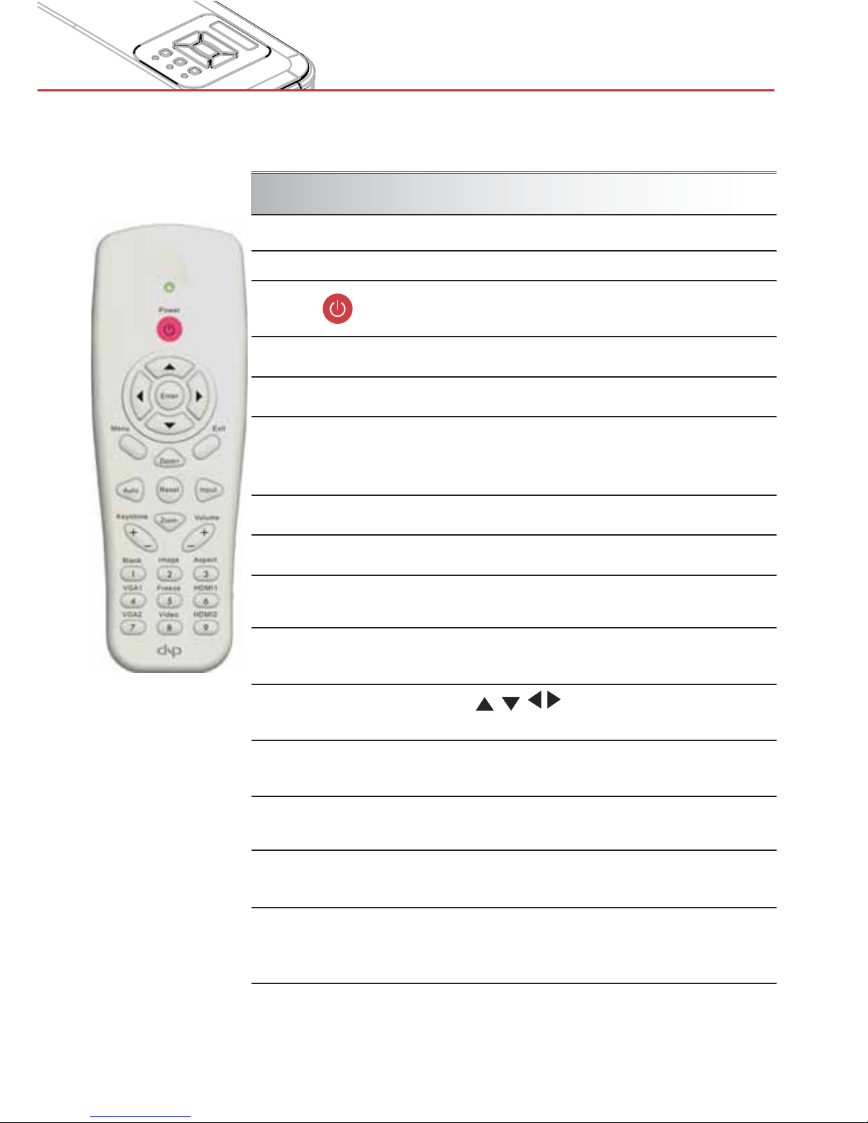
Remote Control
Using the Remote Control
Infrared transmitter Sends signals to the projector.
LED LED Indicator.
Power
Refer to the “Power On/Off the
Projector” section on pages 15-16.
Exit Press “Exit” to close the OSD menu.
Zoom in Zoom in the projector display.
Reset
Return the adjustments and settings to
the factory default values. (except for
lamp counter)
Zoom out Zoom out the projector display.
OK Confirm your item selection.
Source
Press “Source” to select an input
signal.
Auto
Automatically synchronizes the
projector to the input source.
Four Directional
Select Keys
Use
to select items or make
adjustments to your selection.
Keystone +/-
Adjust image distortion caused by tilting
the projector.
Volume +/- Adjust the volume.
Aspect ratio
Use this function to choose your desired aspect ratio.
Menu
Press “Menu” to launch the on-screen
display (OSD) menu. To exit OSD,
press “Menu” again.
Page 20
20
User Controls
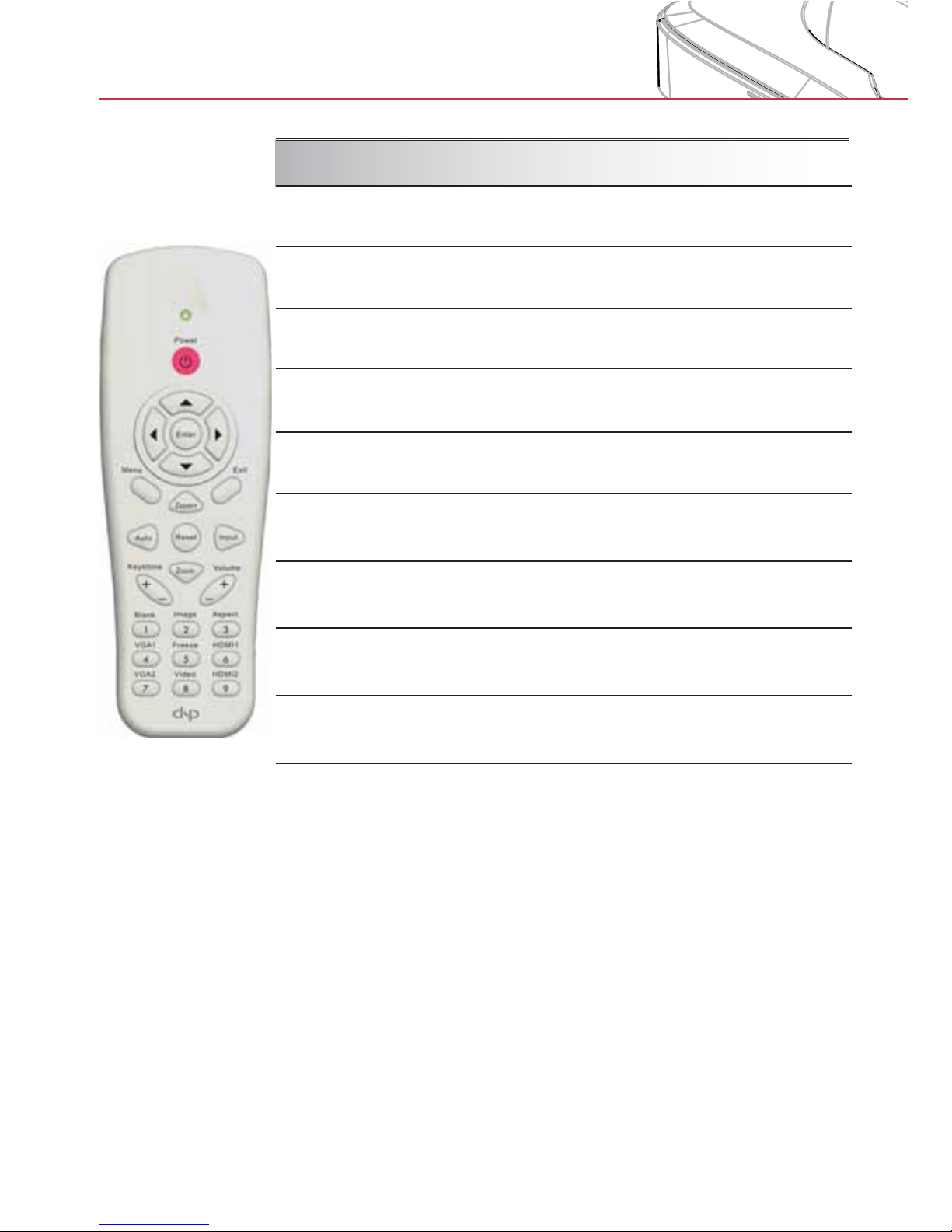
Using the Remote Control
Blank
Momentarily turns off/on audio and
video (black screen on/off).
Image
Select the display mode from Bright,
PC, Movie, Game, and User.
Aspect
Select the desired image format.
VGA1
Press “VGA1” to choose VGA IN 1
connector.
Freeze
Pause the screen image. Press again
to resume the screen image.
HDMI1
Press “HDMI1” to choose HDMI IN 1
connector.
VGA2
Press “VGA2” to choose VGA IN 2
connector.
Video
Press “Video” to choose Composite
video source.
HDMI2
Press “HDMI2” to choose HDMI IN 2
connector.
Page 21
21
User Controls
On-screen Display Menus
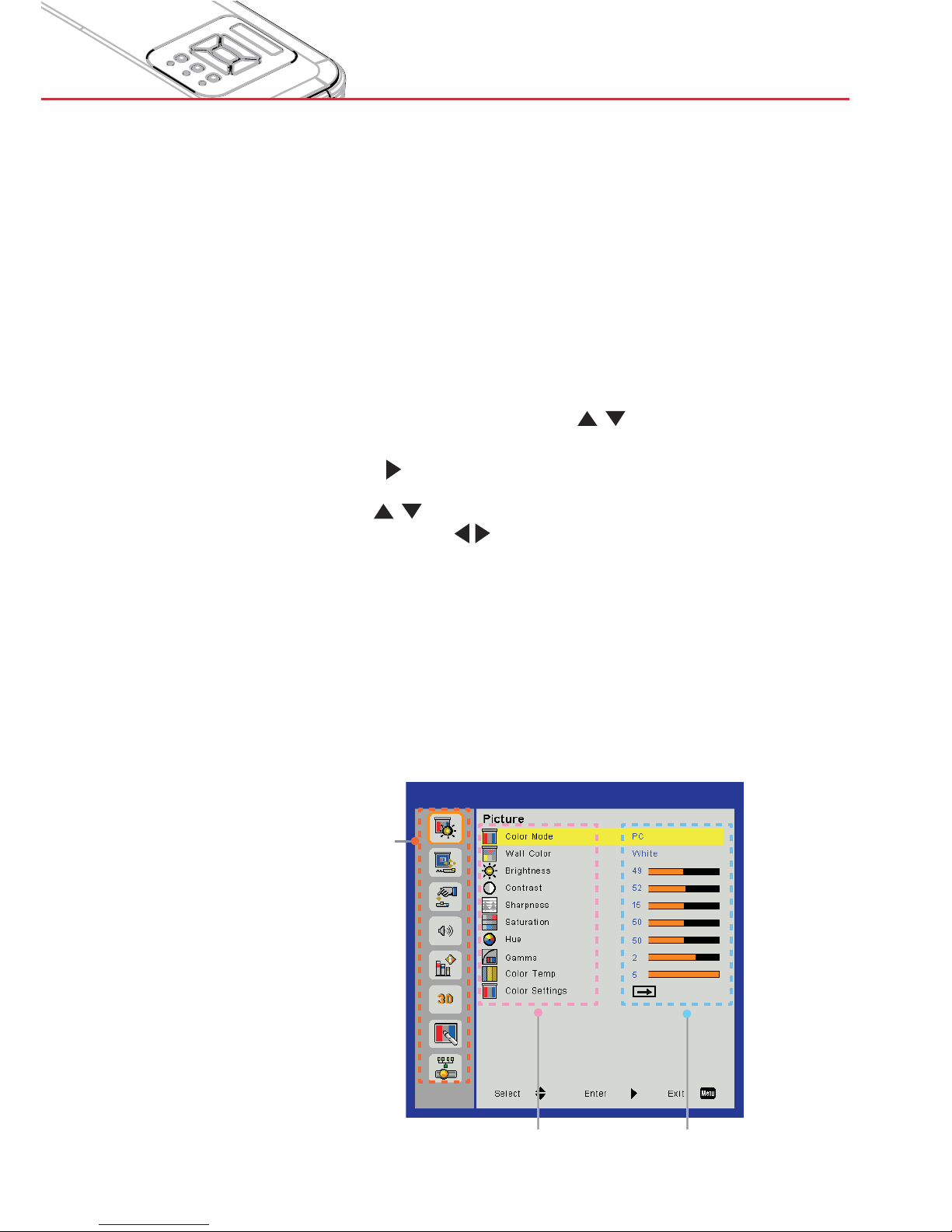
The Projector has multilingual On-screen Display menus that
allow you to make image adjustments and change a variety of
settings.
How to operate
1. To open the OSD menu, press “Menu” on the Remote Control or
Projector Keypad.
2 When OSD is displayed, use the
keys to select any item
in the main menu. While making a selection on a particular page,
press the
or “Enter” key to enter sub menu.
3. Use the
keys to select the desired item and adjust the
settings using the
key.
4. Select the next item to be adjusted in the sub menu and adjust as
described above.
5. Press “Enter” to confirm, and the screen will return to the main
menu.
6. To exit, press “Menu” again. The OSD menu will close and the
projector will automatically save the new settings.
Main Menu
SettingsSub Menu
Page 22
22
User Controls
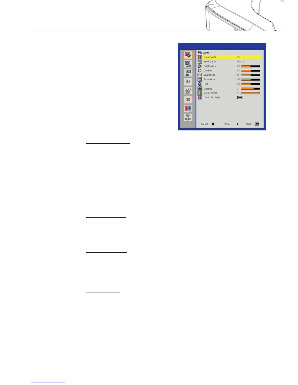
Picture
Color Mode
There are many factory presets optimized for various types of images. Use the ◄ or ► button to select the item.
Bright: For brightness optimization. >
PC: For meeting presentation. >
Movie: For playing video content. >
Game: For game content. >
User: Memorize user’s settings. >
Wall Color
Use this function to obtain an optimized screen image according
to the wall color. You can select from “White”, “Light Yellow”, “Light
Blue”, “Pink”, and “Dark Green”.
Brightness
Adjust the brightness of the image.
Press the ◄ button to darken image. >
Press the ► button to darken image. >
Contrast
The Contrast controls the difference between the lightest and darkest parts of the picture. Adjusting the contrast changes the amount
of black and white in the image.
Press the ◄ button to decrease the contrast. >
Press the ► button to increase the contrast. >
Page 23
23
User Controls
Sharpness
Adjust the sharpness of the image.
Press the ◄ button to decrease the sharpness. >
Press the ► button to increase the sharpness. >
Saturation
Adjust a video image from black and white to fully saturated color.
Press the ◄ button to decrease the amount of saturation in the >
image.
Press the ► button to increase the amount of saturation in the
>
image.
Hue
Adjust the color balance of red and green.
Press the ◄ button to increase the amount of green in the im- >
age.
Press the ► button to increase the amount of red in the image.
>
Gamma
This allows you to adjust the gamma value to obtain the better image contrast for the input.
Color Temp
This allows you to adjust the color temperature. At higher temperature, the screen looks colder; at lower temperature, the screen
looks warmer.
Color Settings
Use these settings for advanced adjustment of the individual
Red,Green,Blue,Cyan,Magenta and Yellow Colors.
> “Sharpness”, “Sat-
uration” and “Hue”
functions are only
supported under
video mode.
Page 24
24
User Controls
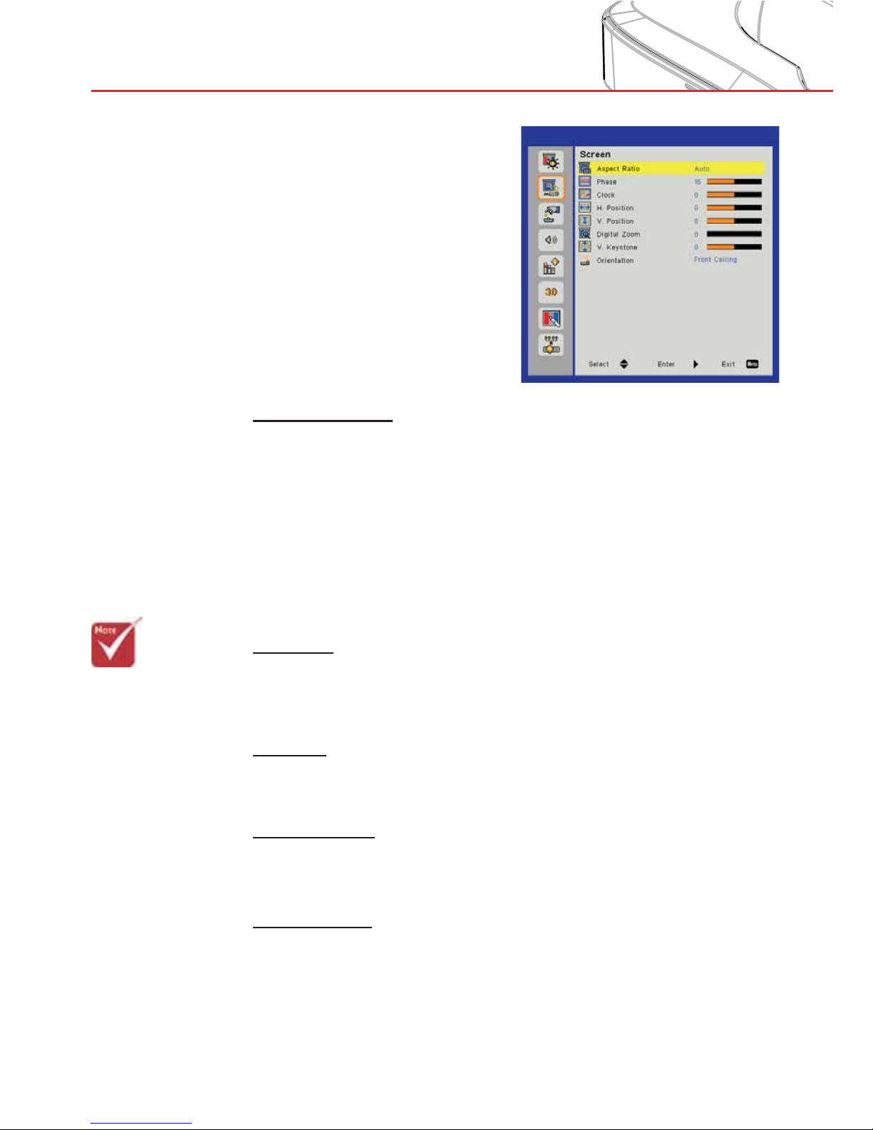
Screen
Aspect Ratio
Auto: Keep the image with original width-height ratio and maxi- >
mize the image to fit native horizontal or vertical pixels.
4:3: The image will be scaled to fit the height of the screen and
>
the width adjusted to display the image using a 4:3 ratio.
16:9: The image will be scaled to fit the width of the screen and
>
the height adjusted to display the image using a 16:9 ratio.
16:10: The image will be scaled to fit the height of the screen
>
and the width adjusted to display the image using a 16:10 ratio.
Phase
Synchronize the signal timing of the display with the graphic card.
If the image appears to be unstable or flickers, use this function to
correct it.
Clock
Adjust to achieve an optimal image when there is a vertical flicker
in the image.
H. Position
Press the ◄ button to move the image left. >
Press the ► button to move the image right. >
V. Position
Press the ◄ button to move the image down. >
Press the ► button to move the image up. >
> “H. Position” and
“V. Position” ranges will depend on
input source.
Page 25
25
User Controls
Digital Zoom
Press the ◄ button to reduce the size of an image. >
Press the ► button to magnify an image on the projection >
screen.
V Keystone
Press the ◄ or ► button to adjust image distortion vertically. If
the image looks trapezoidal, this option can help make the image
rectangular.
Orientation
Front: The image is projected straight on the screen (default for >
dnpA3000HDS).
Front Ceiling: The image is projected upside/down (default for
>
dnpA3000HDI).
Rear: When selected, the image will appear reversed.
>
Rear Ceiling: When selected, the image will appear reversed in >
upside down position.
Page 26
26
User Controls
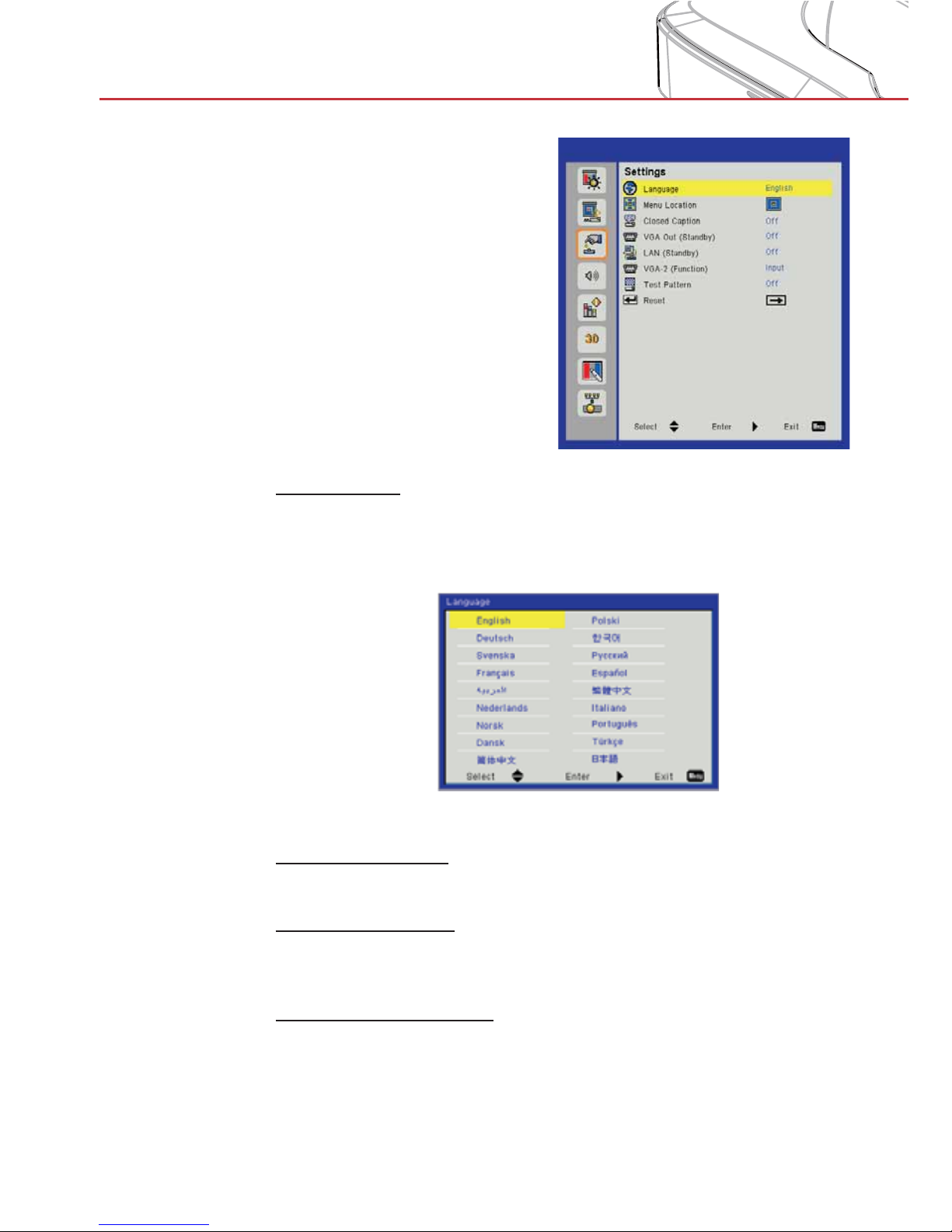
Settings
Language
Choose the multilingual OSD menu. Press the ◄ or ► button
into the sub menu and then use the ▲ or ▼ button to select your
preferred language. Press ► on the remote control to finalize the
selection.
Menu Location
Choose the menu location on the display screen.
Closed Caption
Use this function to enable close caption menu. Select an appropriate closed captions option: Off, CC1, CC2, CC3, and CC4.
VGA Out (Standby)
Choose “On” to enable VGA OUT connection.
Page 27
27
User Controls
LAN (Standby)
Choose “On” to enable LAN connection. Choose “Off” to disable
LAN connection.
VGA-2 (Function)
Input: Choose “Input” to let the VGA port works as a VGA input >
function.
Output: Choose “Output” to enable the VGA Out function once
>
the projector is powered on.
Test Pattern
Display a test pattern.
Reset
Choose “Yes” to return the parameters on all menus to the factory
default settings.
Page 28
28
User Controls
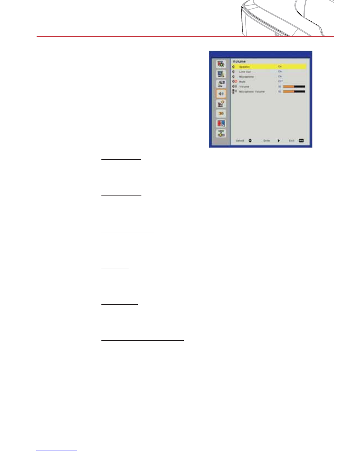
Volume
Speaker
Choose “On” to enable the speaker. >
Choose “Off” to disable the speaker. >
Line Out
Choose “On” to enable the line out function. >
Choose “Off” to disable the line out function. >
Microphone
Choose “On” to enable the microphone. >
Choose “Off” to disable the microphone. >
Mute
Choose “On” to turn mute on. >
Choose “Off” to turn mute off. >
Volume
Press the ◄ button to decrease the volume. >
Press the ► button to increase the volume. >
Microphone Volume
Press the ◄ button to decrease the microphone volume. >
Press the ► button to increase the microphone volume. >
Page 29
29
User Controls
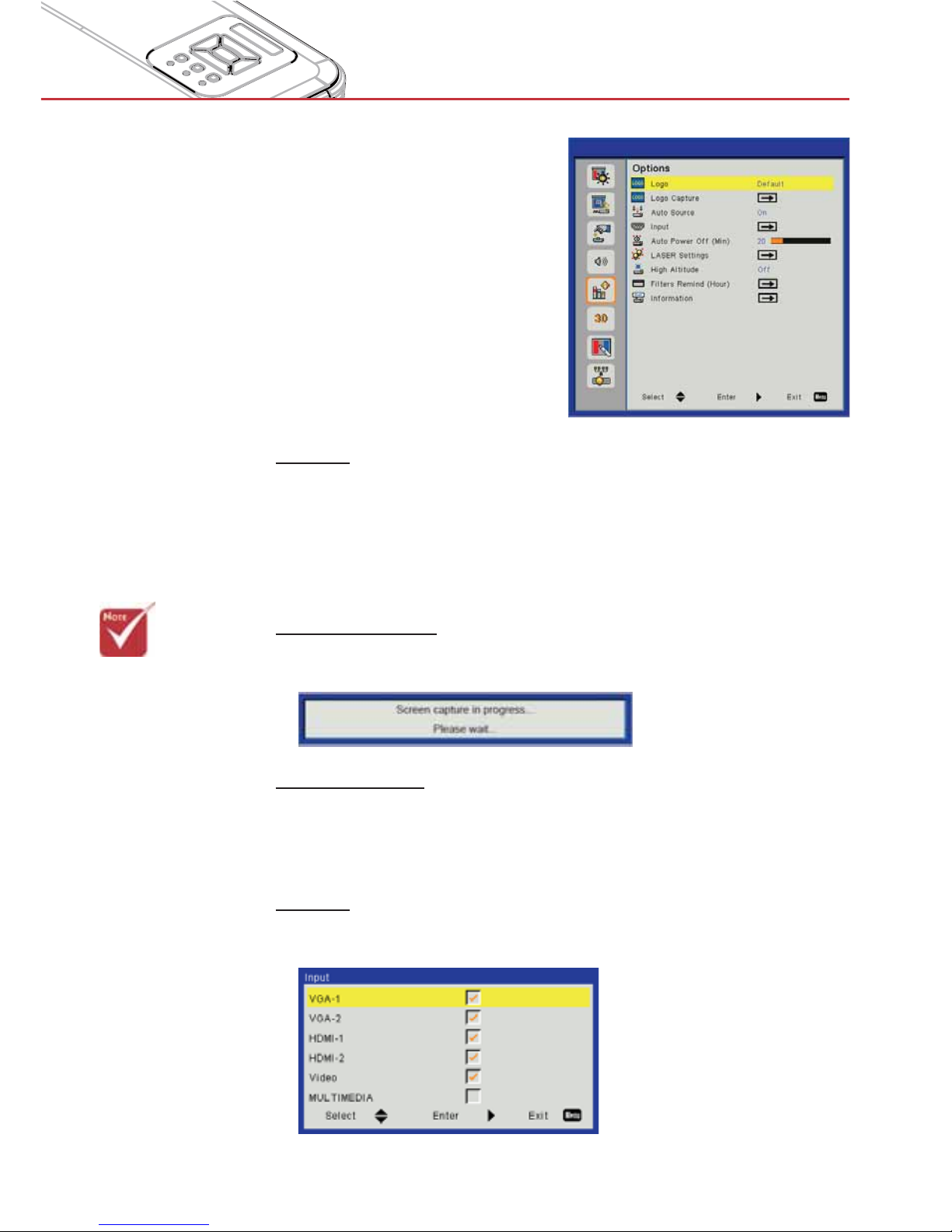
Options
Logo
Use this function to set the desired startup screen. If changes are
made they will take effect the next time the projector is powered
on.
Default: The default startup screen. >
User: Use stored picture from “Logo Capture” function. >
Logo Capture
Press ► button to capture an image of the picture currently displayed on screen.
Auto Source
On: The projector will search for other signals if the current >
input signal is lost.
Off: The projector will only search current input connection.
>
Input
Press ► button to enable/disable input sources. The projector will
not search for inputs that are not selected.
> For successful logo
capture, please
ensure that the onscreen image does
not exceed the
projector’s native
resolution.
> “Logo Capture” is
not available when
3D is enabled.
> Before activating
this function, it is
recommended that
“Aspect Ratio” is
set to “Auto”.
Page 30
30
User Controls
Auto Power Off (Min)
Sets the countdown timer interval. The countdown timer will start,
when there is no signal being sent to the projector. The projector
will automatically power off when the countdown has finished (in
minutes).
Laser Settings
See next page.
High Altitude
On: The built-in fans run at high speed. Select this option when >
using the projector at altitudes above 2500 feet/762 meters or
higher.
Off: The built-in fans automatically run at a variable speed ac-
>
cording to the internal temperature.
Filters Remind (Hour)
Filters Remind (Hour): Set the filter reminder time. >
Cleaning Up Remind: Select “Yes” to reset the dust filter hour >
counter after replacing or cleaning the dust filter.
Information
Display the projector information for model name, SNID, source,
resolution, software version, and aspect ratio on the screen.
Page 31
31
User Controls
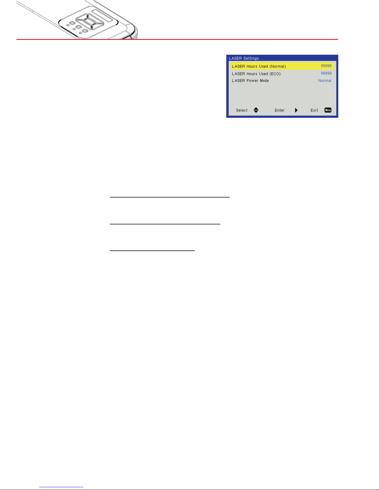
Options |
Laser Settings
Laser Hours Used (Normal)
Display the projection time of normal mode.
Laser Hours Used (ECO)
Display the projection time of ECO mode.
Laser Power Mode
Normal: Normal mode. >
ECO: Use this function to dim the projector lamp which will >
lower power consumption and extend the lamp life.
Page 32
32
User Controls
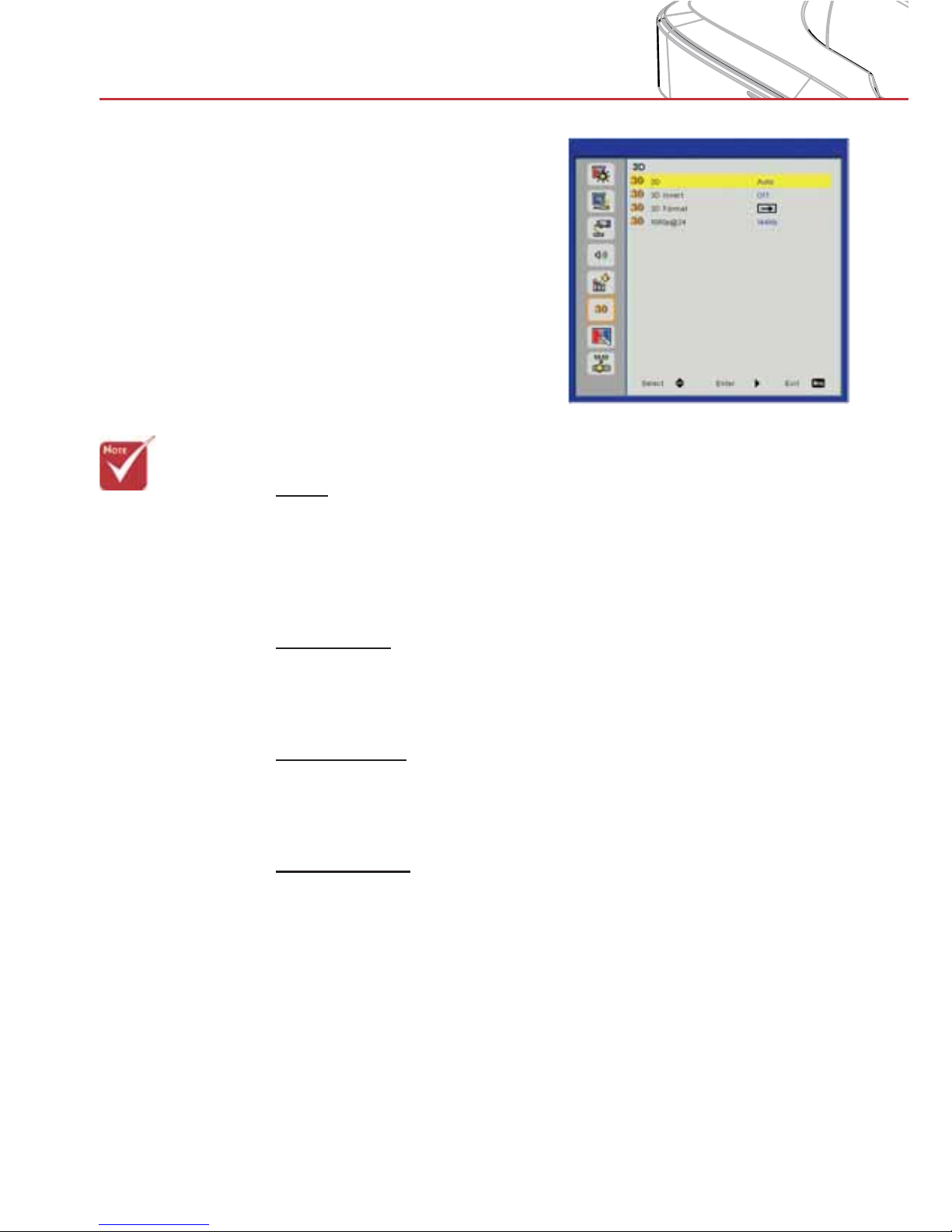
3D
3D
Auto: When a HDMI 1.4a 3D timing identification signal is de- >
tected, the 3D image is selected automatically.
Choose “On” to enable the 3D function.
>
Choose “Off” to disable the 3D function. >
3D Invert
If you see a discrete or overlapping image while using DLP 3D
glasses, you may need to execute “Invert” to get the best match of
left/right image sequence to get the correct image.
3D Format
Use this feature to select the 3D format. Options are: “Frame
Packing”, “Side-by-Side (Half)”, “Top and Bottom”, “Frame Sequential”, and “Field Sequential”.
1080p@24
Use this feature to select 96 or 144Hz refresh rate as using 3D
glasses in the1080p @ 24 frame packing.
> “Frame Sequen-
tial” is supported
the DLP Link 3D
input signals from
VGA / HDMI connector.
> “Frame Sequen-
tial” / “Field Sequential” are supported the HQFS
3D input signals
from Composite/
S-Video connector
connector.
> “Frame Pack-
ing” / “Side-bySide(Half)” / “Top
and Bottom” are
supported from
HDMI 1.4a 3D
input signals.
Page 33
33
User Controls
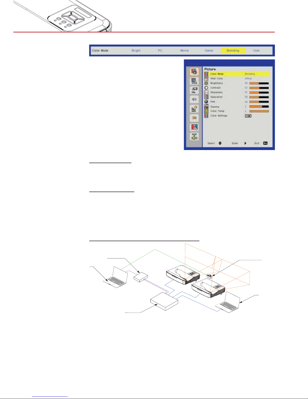
Blending
mode
Brightness
For user to manually adjust the brightness of projectors used in
blending mode.
Color Temp
For user to manually map the color temperature of projectors used
in blending mode.
Blending application
Example of system architecture
PC
PC
Network Switch
Blending Box
Calibration Camera
Laptop, Switch and Camera is for image calibration only >
Laptop Source: Image source >
Blending Box >
Multiple projectors (here two) >
For more details, please check the blending HW/SW specifica- >
tions
Page 34
34
User Controls
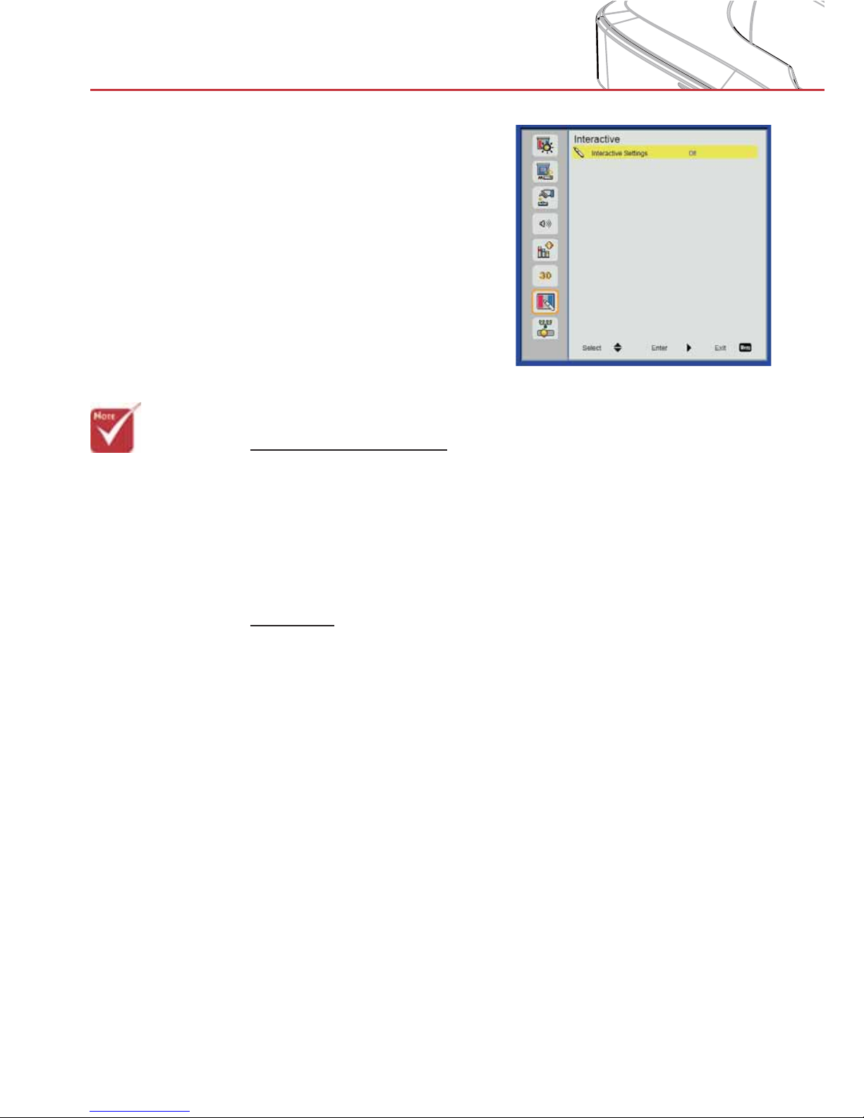
Interactive
Interactive Settings
Choose “On” to enable the Interactive function. >
Choose “Off” to disable the Interactive function. >
Use the Mini USB cable to connect PC/laptop and projector. Connect before using the interactive function. After you complete the
Interactive Settings in OSD, use the Mini USB cable to connect a
NB/desktop to the projector.
IR Pen
Usage Notice
Please follow all warnings, precautions and maintenance as recommended in this user’s manual.
Precautions
IR camera on the projector receives infrared signal illuminated
from IR pen. To operate normally:
IR camera should face the projected image on the wall. >
Remove any obstacle between the IR camera and the projected >
image.
Do not place other infrared communication devices, lighting
>
equipments, residential heating equipments, etc. nearby.
Use the enclosed USB cable (maximum length: 5m).
>
To extend the USB cable length over 5m, a certified active >
extension USB cable is required.
> Please note that
the Interaction
function is only for
the HDI model.
The interactive
function is not
available in the
HDS model.
> The Interac-
tive function is
available when
displaying graphic
source from
HDMI/VGA input.
Other sources are
not supported.
> If “3D” or “Dynam-
ic Black” function
is enabled the “Interactive” feature
is disabled.
Page 35
35
User Controls
Step 1: Install Utility Software
A. System requirements
To ensure normal operation of the interactive function follow below
requirements:
System requirements
Operating system Microsoft Windows XP (SP3)/Windows 7
(32bit/64bit)/Windows 8/ Windows 8.1
(. NET Framework 4.0 must be installed)
Mac OS X(10.7~10.10)
CPU Intel® Core™ i3 or above
Memory 2GB or more
B. Download the latest version of the software from www.dnp-
screens.com and install on the PC.
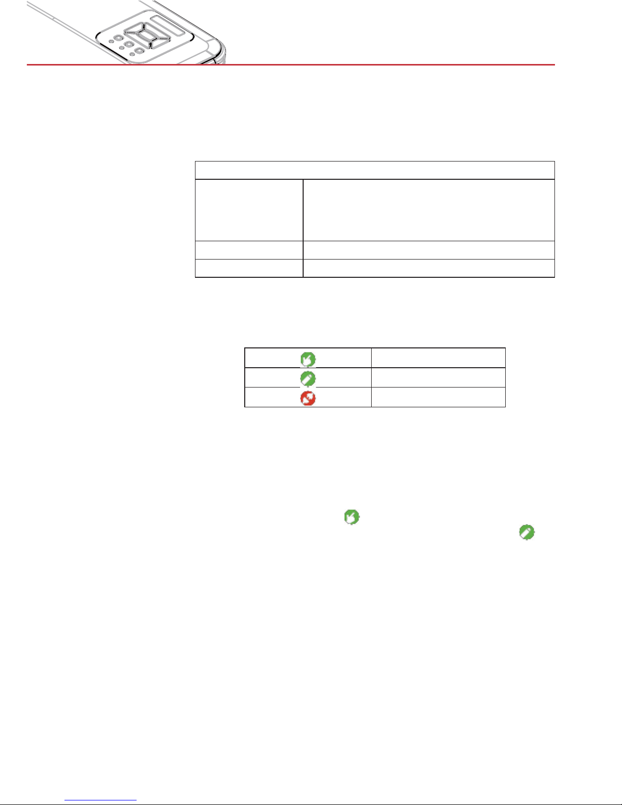
C. A utility icon indicator as below will appear in the Windows/Mac
OS taskbar when running software utility.
Finger/Stylus mode
Active Pen mode
Disconnected
D. Connect the PC to the projector with the enclosed USB cable
and a signal cable before proceeding.
Step 2: Operation Mode
Windows 7 and Windows 8 operating systems support multi-point
touch control (not available for Windows XP and Mac OS X).
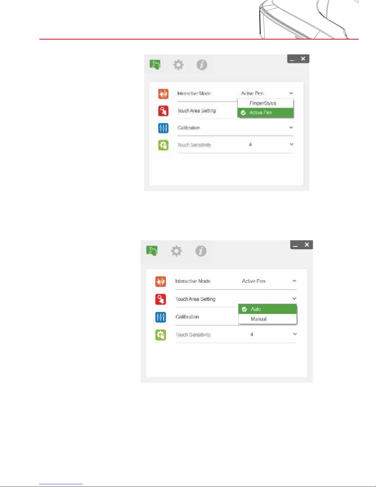
Select Finger/Stylus Mode (
) for multi-point touch if using the
LaserCurtain (optional accessory).
Select Active Pen Mode (g)
when using the light pen(IR pen).
Page 36
36
User Controls
IR pen operation mode is for single-point-touch only.
Step 3: Touch Area Setting
A. Select Auto Touch Area Setting:
Note:
Quit all software applications >
Reduce ambient light >
Do not obstruct or shake the lens during Touch Area Setting >
Page 37
37
User Controls
Check if the projected image is clear. If not, adjust the focus to >
sharpen the image
If an error message pops up after auto setting, check surround-
>
ings and redo
If the error message continues to pop up, switch to Manual
>
Touch Area Setting
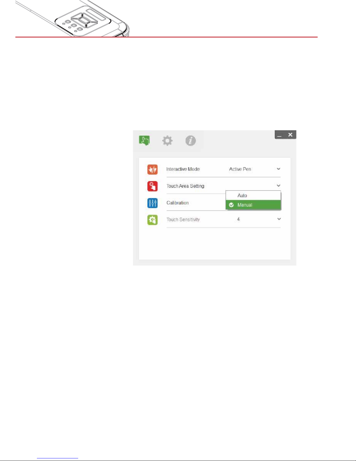
B. Select Manual Touch Area Setting:
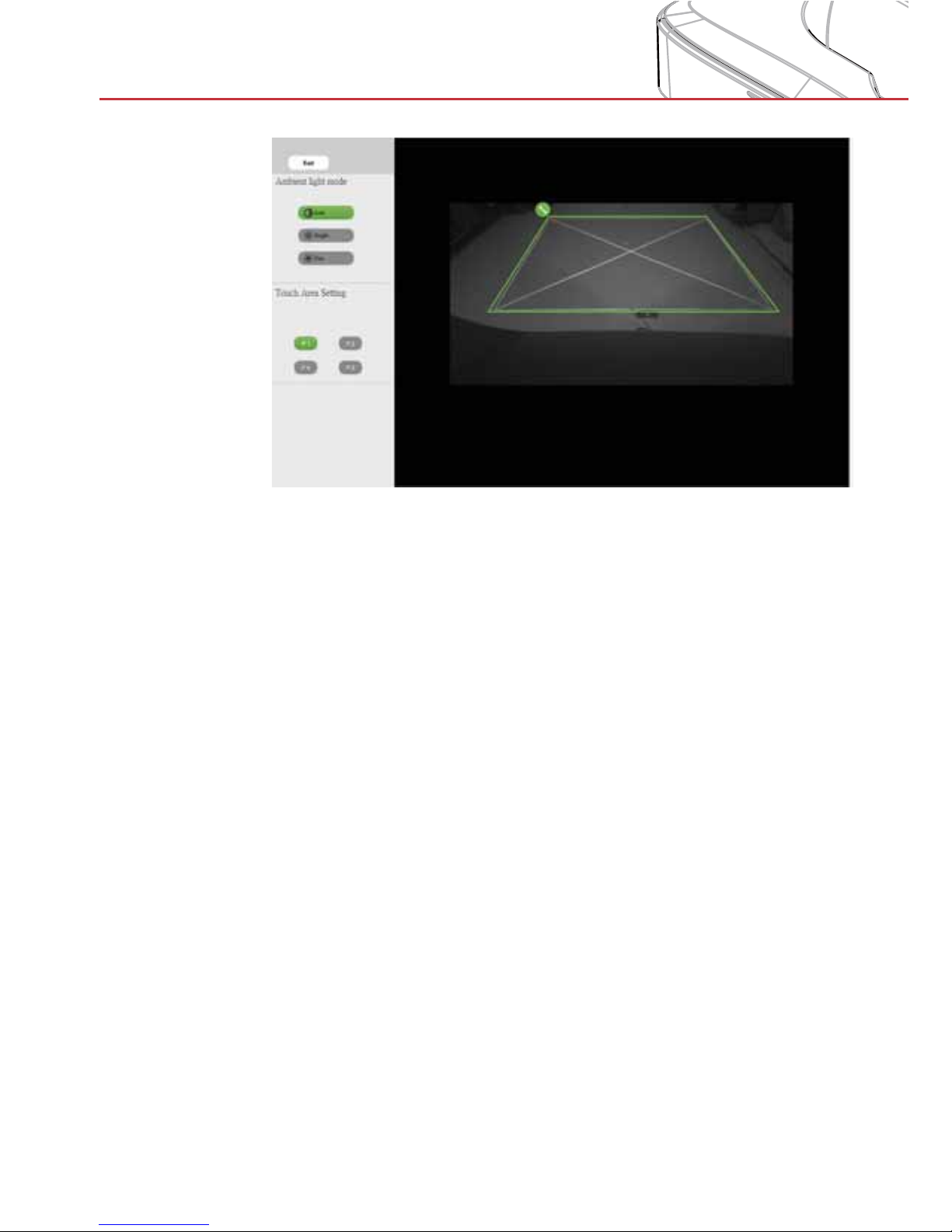
B-1. After the camera captures the projected image, a Touch Area
window will pop up. The working touch area is defined by a
green frame. If the captured image is not clear enough, reselect “Ambient light mode selection” from “Auto” to “Bright” or
“Dim” according to the actual ambient light conditions.
NOTE! The captured image shows the actual camera view,
which may be reversed from the projected image (depending
on projector positioning). P1 could be lower right corner, P2
lower left corner etc.
Page 38
38
User Controls
B-2. Touch Area Boundary Fine-tuning
Step 1: Click on P1; use the mouse to drag the green corner
P1 just outside the corner of the projected white
frame.
Step 2:
Adjust P2 to P4 accordingly; ensure that the adjust-
able green zone (the working touch area) completely
covers the projected white frame.
Step 3: Double-check that the green frame is perfectly
outside the projected white frame. If not, fine-tune
again.
B-3. When the Touch Area is correctly set click exit.
Page 39
39
User Controls
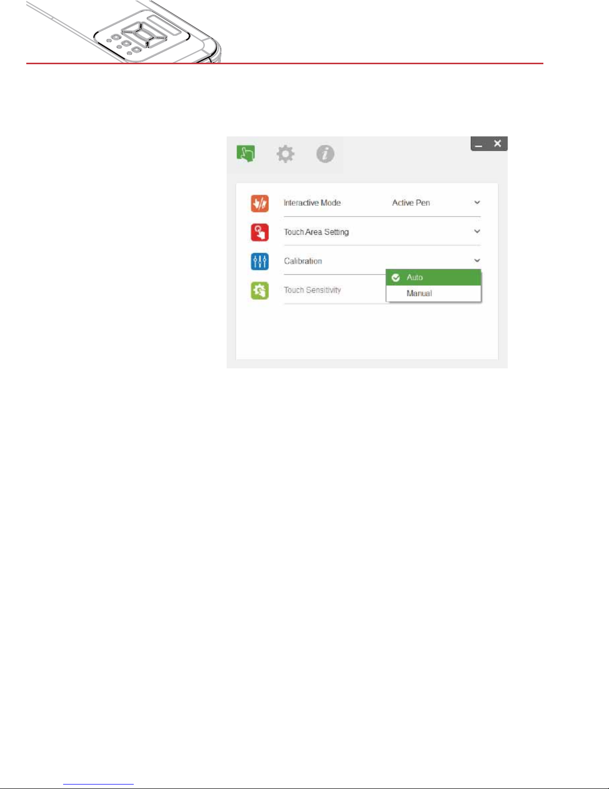
Step 4: Calibration
A. Select Auto Calibration to automatically calibrate. Do not ob-
struct the camera view while auto-calibrating.
Note:
If the Auto Calibration was not successful, follow below steps to
trouble-shoot and run the Auto Calibration again.
Close all software applications >
Reduce ambient light >
Do not obstruct or shake the lens during calibration >
Check if the projected image is clear. If not, adjust the focus to >
sharpen the image
If you are not satisfied with the calibration result or if an Auto Calibration error message continues to pop up on the screen, switch to
Manual Calibration.
Page 40
40
User Controls
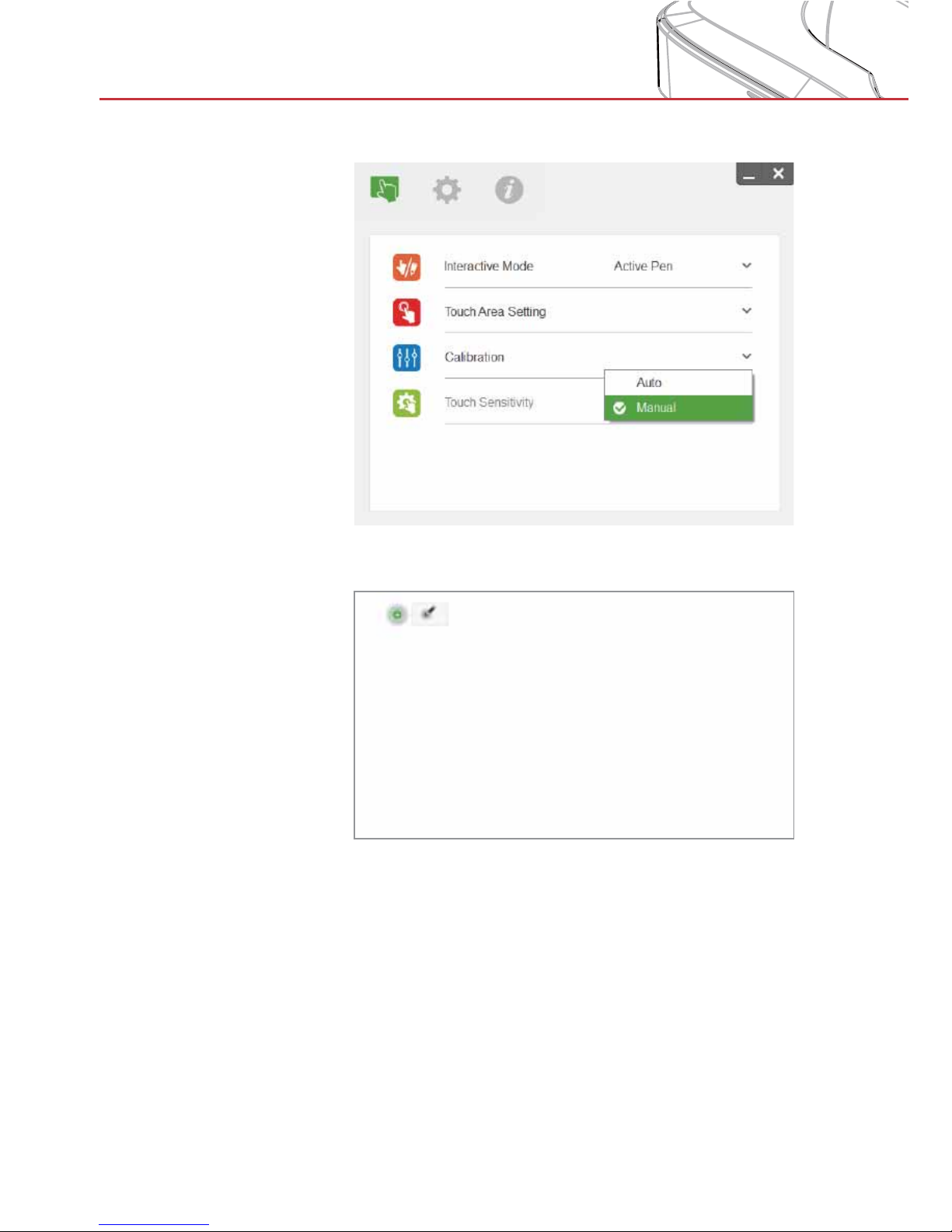
B. Select Manual Calibration to manually adjust the touch accu-
racy:
Note: Manual Calibration is suggested for better accuracy.
Multiple on-screen calibration points are used to adjust the touch
accuracy.
Use finger or pen, depending on operation mode, to calibrate.
Step 1: The calibration target is displayed on the screen (start in
upper left corner).
Step 2: Press and hold in the center of the target until the center
changes color, which indicates the point is set.
Step 3: Release. The next calibration target will display.
Step 4: Redo steps 2 and 3 until calibration is complete.
Page 41
41
User Controls
If calibration is not successful do the following:
Close all software applications >
Reduce ambient light >
Do not obstruct or shake the lens during calibration >
Check if the projected image is clear. If not, adjust the focus to >
sharpen the image
Check that the Touch Area completely covers the screen
>
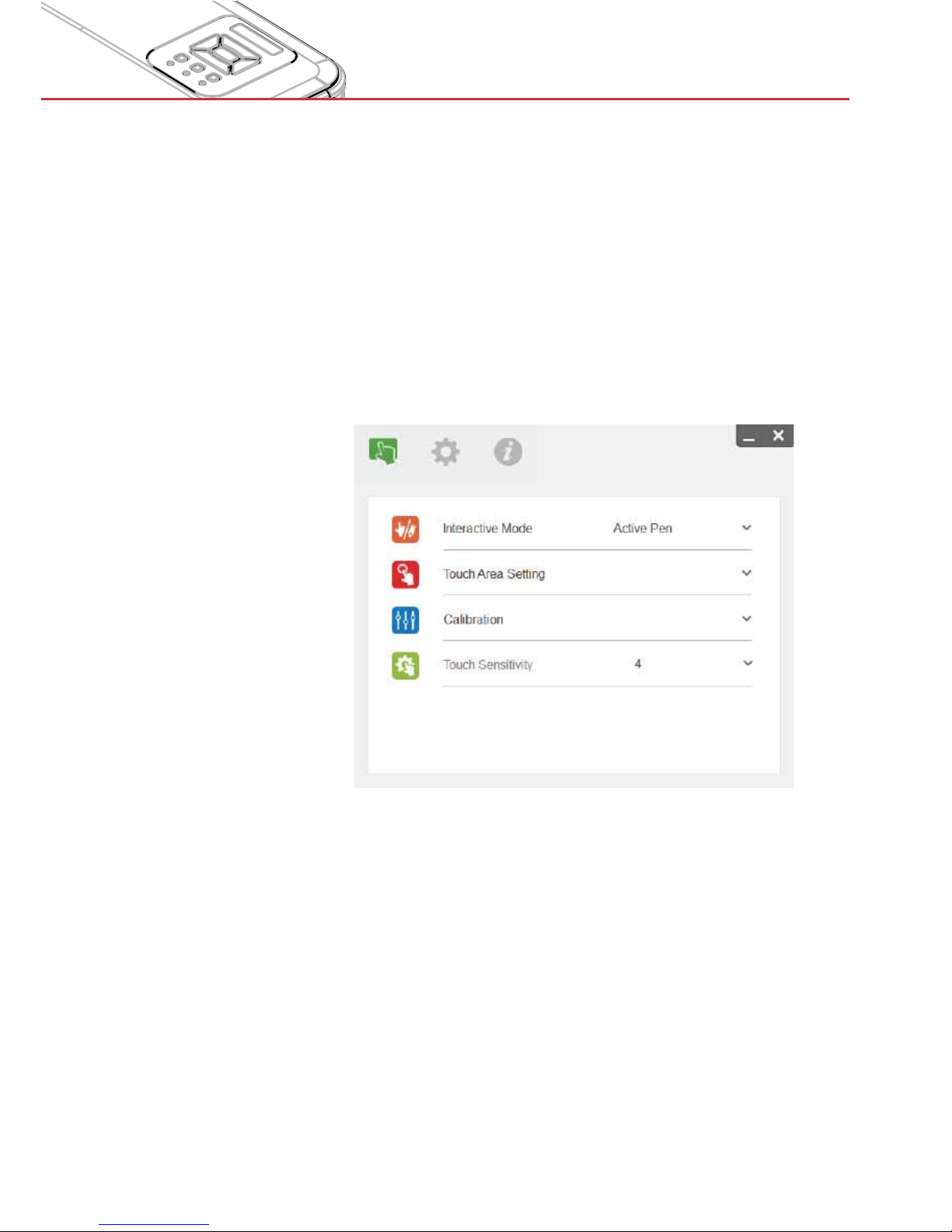
Step 5: Touch Sensitivity
When touch function is unresponsive or writing is intermittent. You
can adjust the sensitivity by adjusting Touch Sensitivity level:
- Default: 4
- Max.: 10 (most sensitive)
- Min.: 0 (least sensitive)
Note: Touch Sensitivity is not adjustable under Active Pen
Mode.
Page 42
42
User Controls
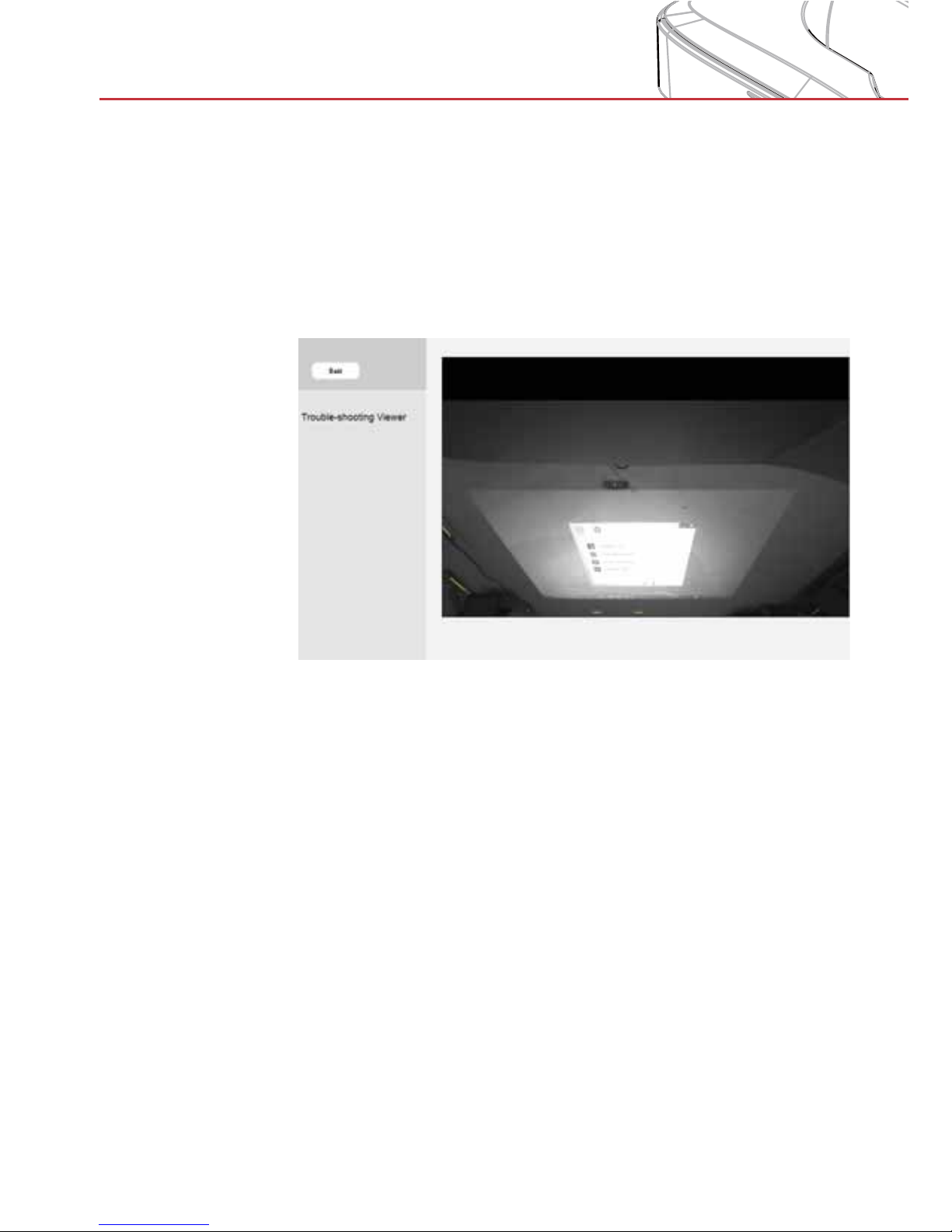
Step 6: Trouble-shooting Viewer
Sometimes infrared light (IR light) from ambient light sources interfere with touch performance. The troubleshooting viewer shows
real time images for debugging purposes. Any light interference
is marked in green. If a green obstacle appears within the image
area locate the source and prevent it from interfering.
Note: Interactive function is disabled under trouble-shooting
viewer, use mouse to click exit.
Page 43
43
User Controls
Appendix : Specification
I. General Specifications
Calibration
Auto Calibration
Manual Calibration
Multi-touch 10-touch points (Win 7 and Win8 compliant)
Display mode Support Ceiling mode only
II. Installation Software
System
Requirements
OS
Required:
Microsoft Windows XP (SP3):
>
Mouse mode supported.
Windows 7/Windows 8: Touch
>
mode-10 touch points supported and Mouse mode
supported
(Windows: .NET Framework
>
4.0 installation is required)
Max OS X(10.7~10.10)
>
Processor
Type
Intel CoreTM i3 or above
RAM 2GB or More
Page 44
44
User Controls
LAN
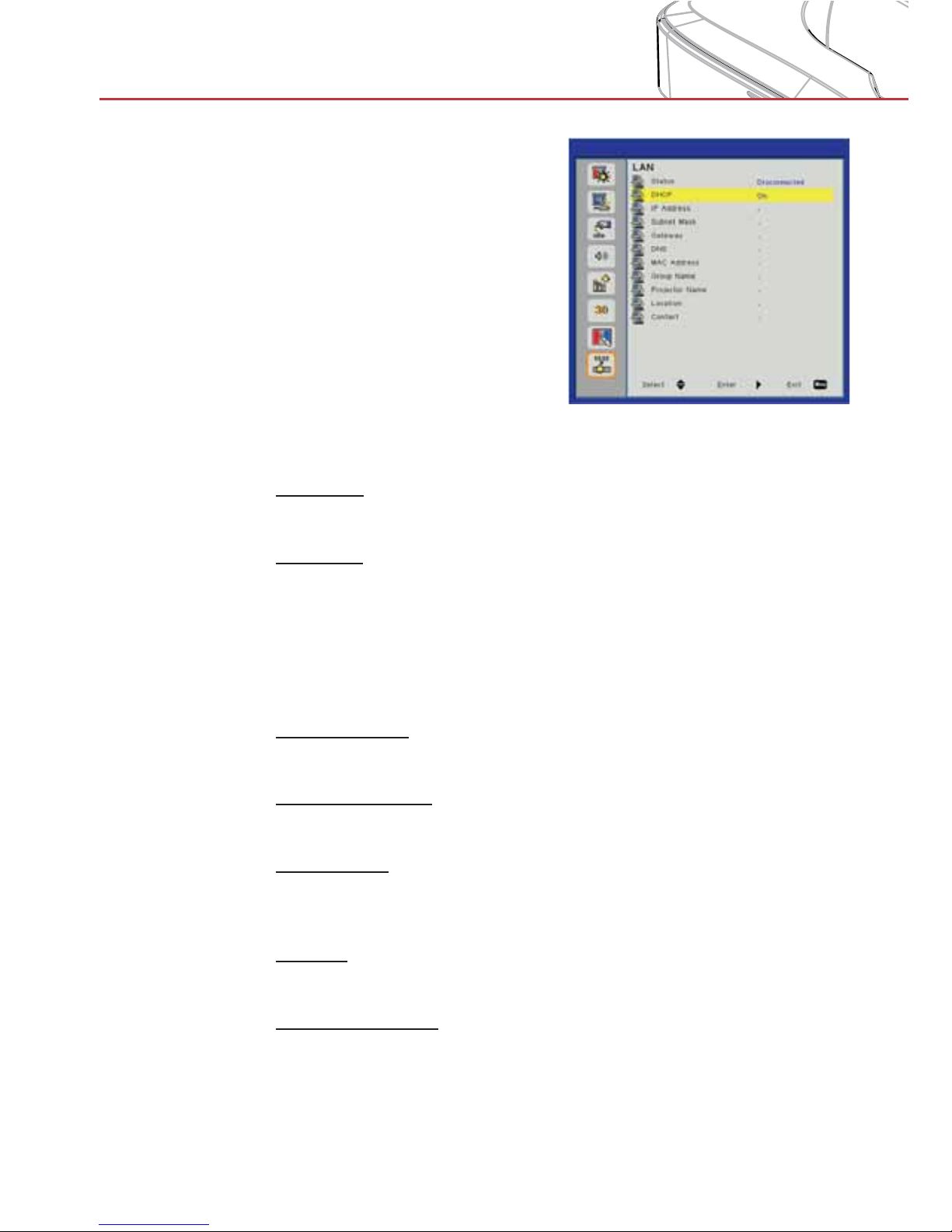
Status
Display the network connection status.
DHCP
Configure the DHCP settings.
On: Choose “On” to let the projector to obtain an IP address >
automatically from your network.
Off: Choose “Off” to assign IP, Subnet Mask, Gateway, and
>
DNS configuration manually.
IP Address
Display an IP address.
Subnet Mask
Display the subnet mask number.
Gateway
Display the default gateway of the network connected to the projector.
DNS
Display the DNS number.
MAC Address
Display the MAC address.
Page 45
45
User Controls
Group Name
Display the group name.
Projector Name
Display the projector name.
Location
Display the projector location.
Contact
Display the contact information.
Page 46
46
User Controls
How to use a web browser to contro l your projector
You can control the projector remotely via a web browser on your controlling device. You
can connect directly or via a network.
1. When making LAN connection from your computer to the projector:
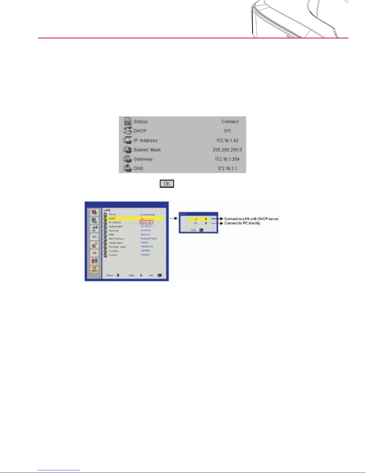
Step 1: Turn on DHCP to allow a DHCP server to automatically assign an IP, or manually
enter the required network information.
Step 2: Then choose apply and press button to complete the configuration process.
Step 3: Find the IP Address from the LAN function of the projector as below.
1) Connect to LAN with DHCP server, please select DHCP ON and go to Step 10
2) Connect to PC directly, please select DHCP OFF
Page 47
47
User Controls
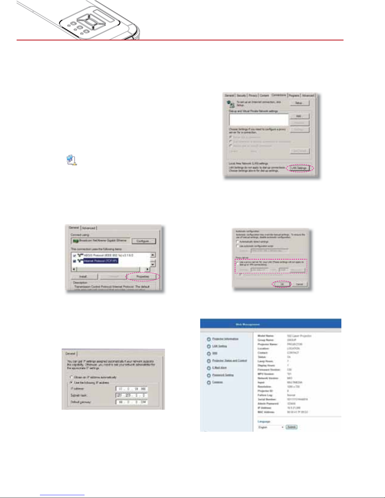
Step 8: To open Internet Options, in IE web
browser, click Internet Options,
click the Connections tab and click
“LAN Settings...”.
Step 9: The Local Area Network (LAN)
Setting dialog box appears. In the
Proxy Server area, uncheck Use
a proxy server for your LAN, then
click “OK” button twice.
Step 10: Open your web browser and type
in the IP address in the URL and
press “Enter”.
Step 4: Select apply and press “Enter”
button to submit function or press
“menu” key to exit.
Step 5: To open Network Connections,
click Start, click Control Panel,
click Network and Internet
Connections, and then click
Network Connections. Click the
connection you want to configure,
and then, under Network Tasks
, click Change settings of this
connection.
Step 6: On the General tab, under
This connection uses the
following items, click Internet
Protocol (TCP/IP), and then click
“Properties.”
Step 7: Click Use the following IP
address, and type in as below:
1) IP address: 10.0.21.100
2) Subnet mask: 255.255.0.0
3) Default gateway: 10.0.0.254
Page 48
48
User Controls
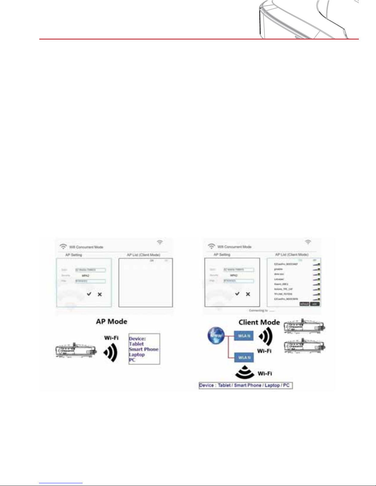
2. When making Wi-Fi connection between your computer and the
projector
Step 1: Setup the WiFi connection
Insert a WiFi dongle (optional/accessory) in the USB socket in the projector.
>
Go to Input → Multimedia → Settings → WiFi. >
Define SSID/AP name and password in the AP settings menu. Note! The password >
must be minimum 8 characters. Press exit on the remote control to exit the virtual
keyboard to be able to save the settings.
You are now ready to connect your wireless device directly to the projector (AP
>
mode).
If you want to connect via a WiFi network (client mode) you must connect the projec-
>
tor and the wireless device to a common WiFi network and ensure that the network
allows connected units to see each other.
Turn ON the AP list to see available wireless networks (Client mode only).
>
Connect the projector to the desired wireless network (Client mode only). >
Exit Settings >
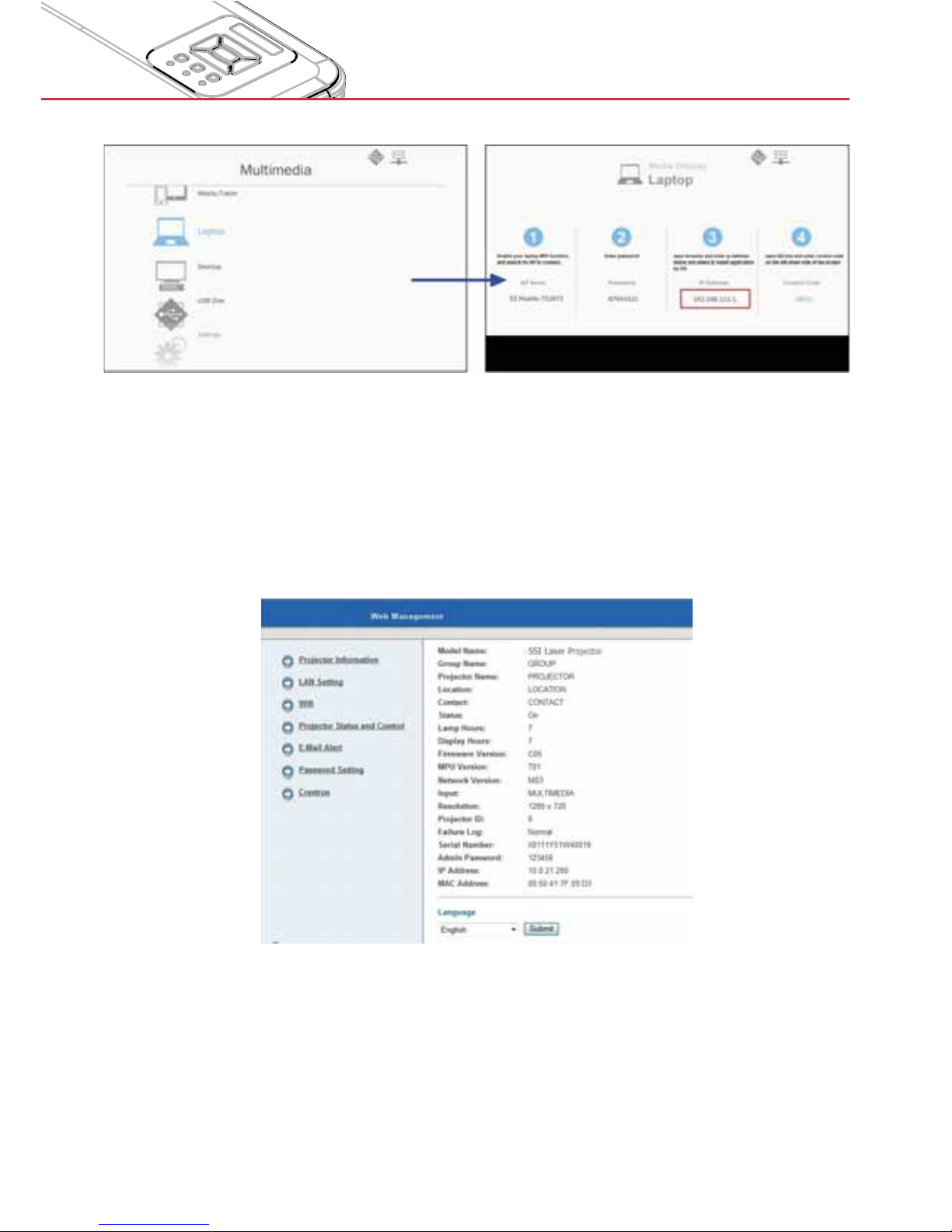
Step 2: Connect to the projector (AP Mode only)
Go to Input → Multimedia → Mobile/Tablet or Laptop (depending on device)
>
On your mobile/tablet or laptop: Open the list of available wireless networks and con- >
nect to the listed AP using the displayed password
Page 49
49
User Controls
Step 3: Access to the Web Management Page in AP mode.
Open your web browser and type in the IP address 192.168.111.1 in the URL then press
“Enter”.
Projector Information
User can retrieve the Projector Information in this page and select the content display in
different languages.
Page 50
50
User Controls
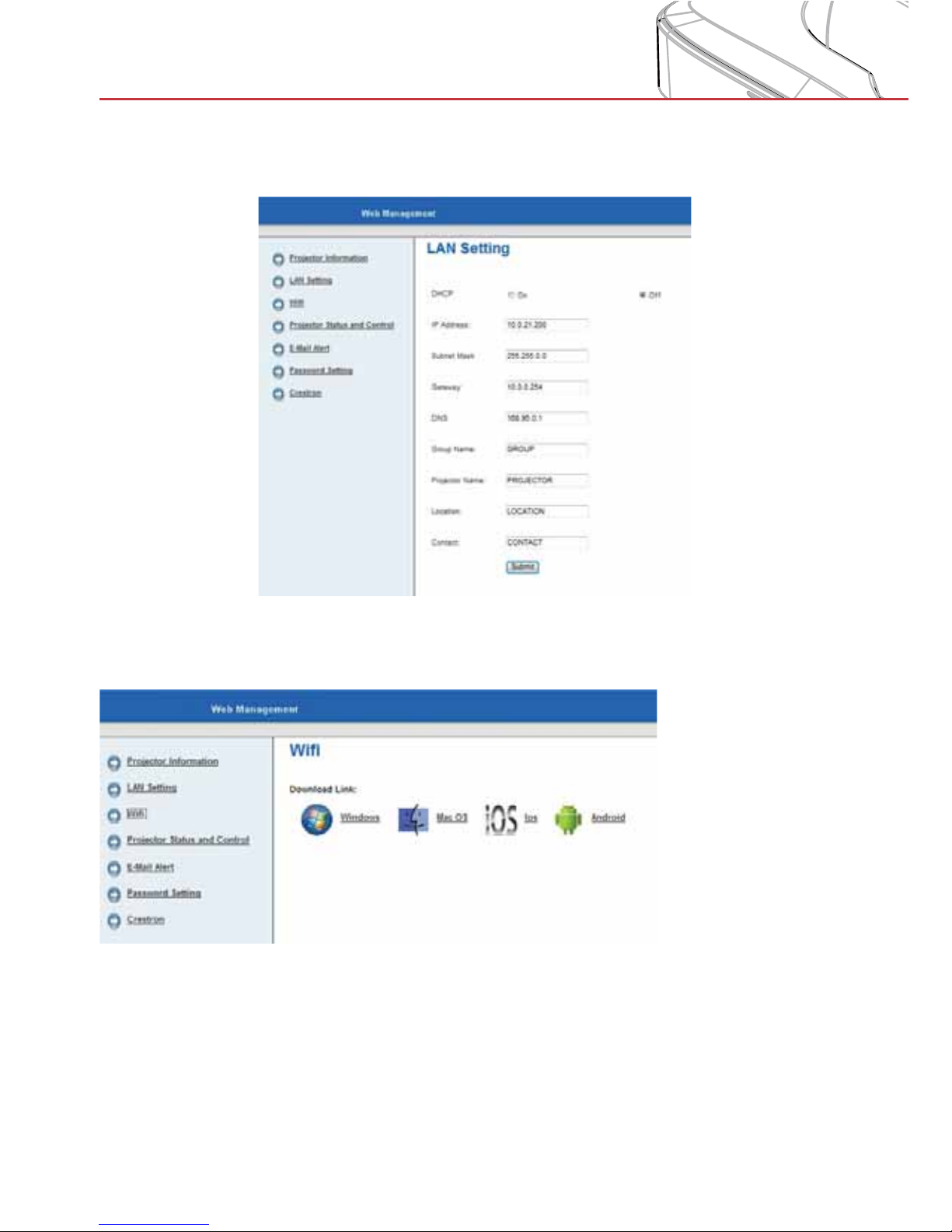
LAN Setting
User can configure LAN parameters and edit the projector information in this page.
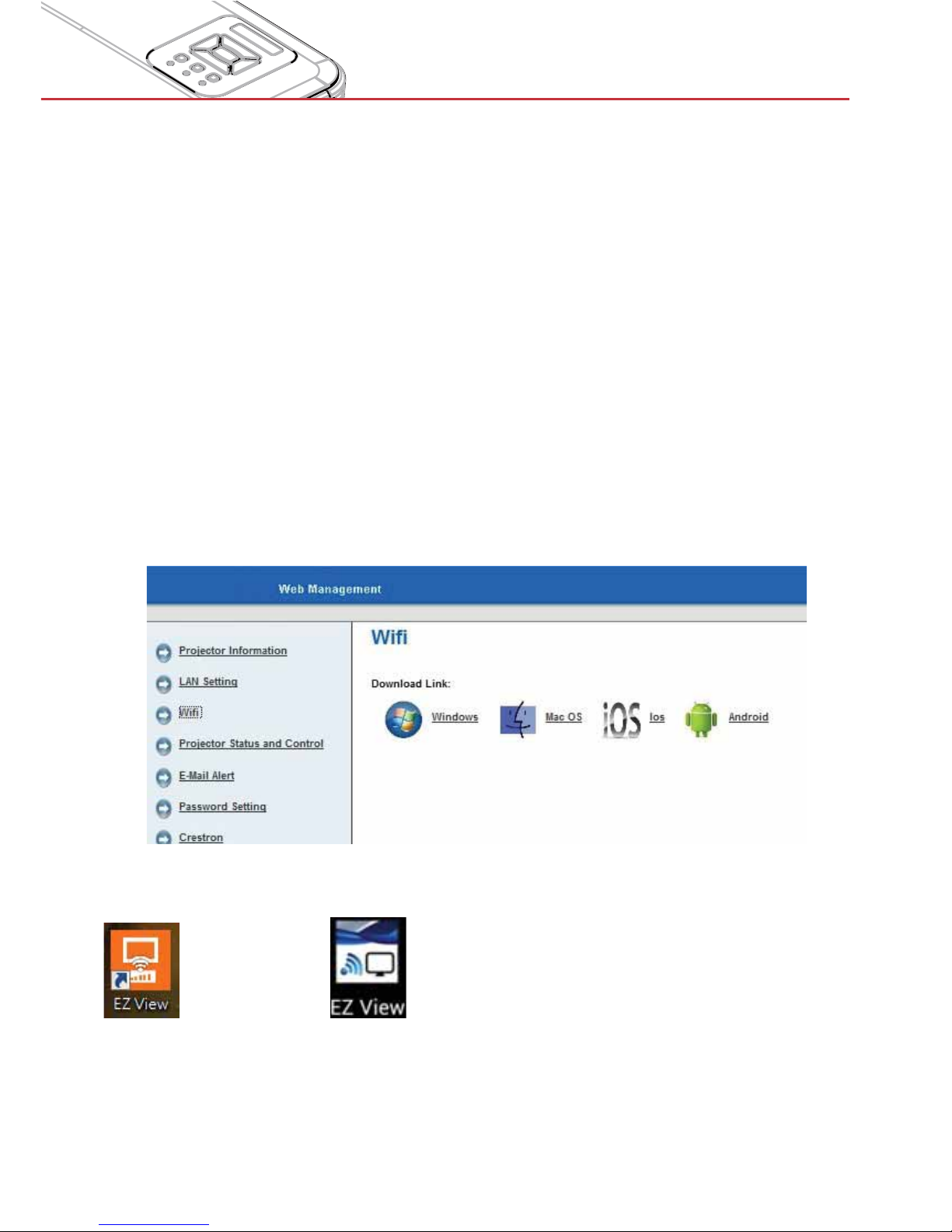
Wi-Fi
User can install EZView for different platforms and operating systems.
Page 51
51
User Controls
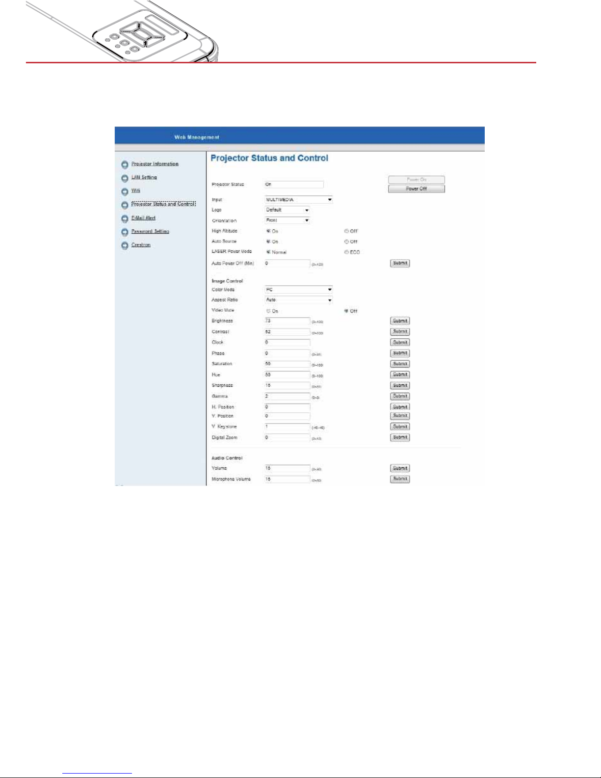
Projector Status and Control
User can control the projector in this page.
Page 52
52
User Controls
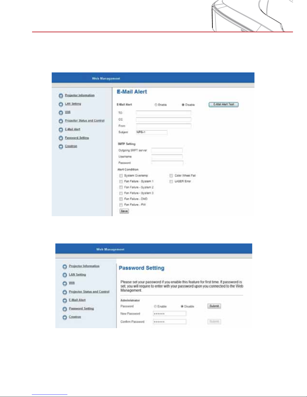
E-mail Alert
User can assign the email address and categorize alert notice.
Password Setting
User can set the password to get access to web management.
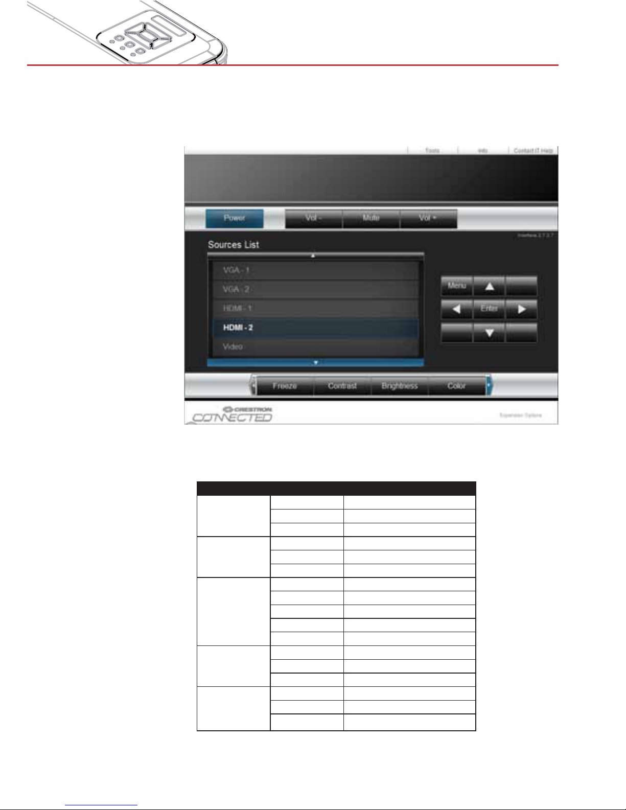
Crestron control: See page 73 on how to control the projector via Crestron flash UI.
Page 53
53
Multimedia
EZView
EZView is an APP and software that can wirelessly transfer content from a smart phone,
tablet, laptop, desktop, etc. and have it displayed on a LaserPanel projector. There is a
limitation to what you can do via the APP whilst using the software has no other limitation
than a maximum resolution of 720p.
EZView APP features:
Support local photo, document(PDF and Office files) gallery and do sketch
>
Support local video >
Display Web pages and support sketch function as well >
Streaming image data from camera >
Support Web Video like Youtube >
Support Dropbox >
Screen Display via EZView APP or software
Step 1: Install the EZView tool on your device according to the device operating system.
Step 2: Start EZView on the device by clicking below icon.
on PC or Laptop, on tablet or smart phone.
Page 54
54
Multimedia
EZView on PC or Laptop
Step 1: Connect your PC/Laptop to the projector (AP mode) or connect both the PC/Laptop
and the projector to a common WiFi or LAN network (Client mode)
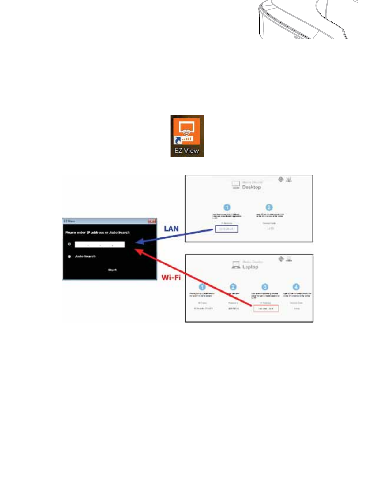
Step 2: Start EZView on the device by clicking below icon on PC or Laptop and access
Multimedia mode on the projector.
Step 3: Enter the IP address. (choose either from Wi-Fi or LAN connection)
Page 55
55
Multimedia
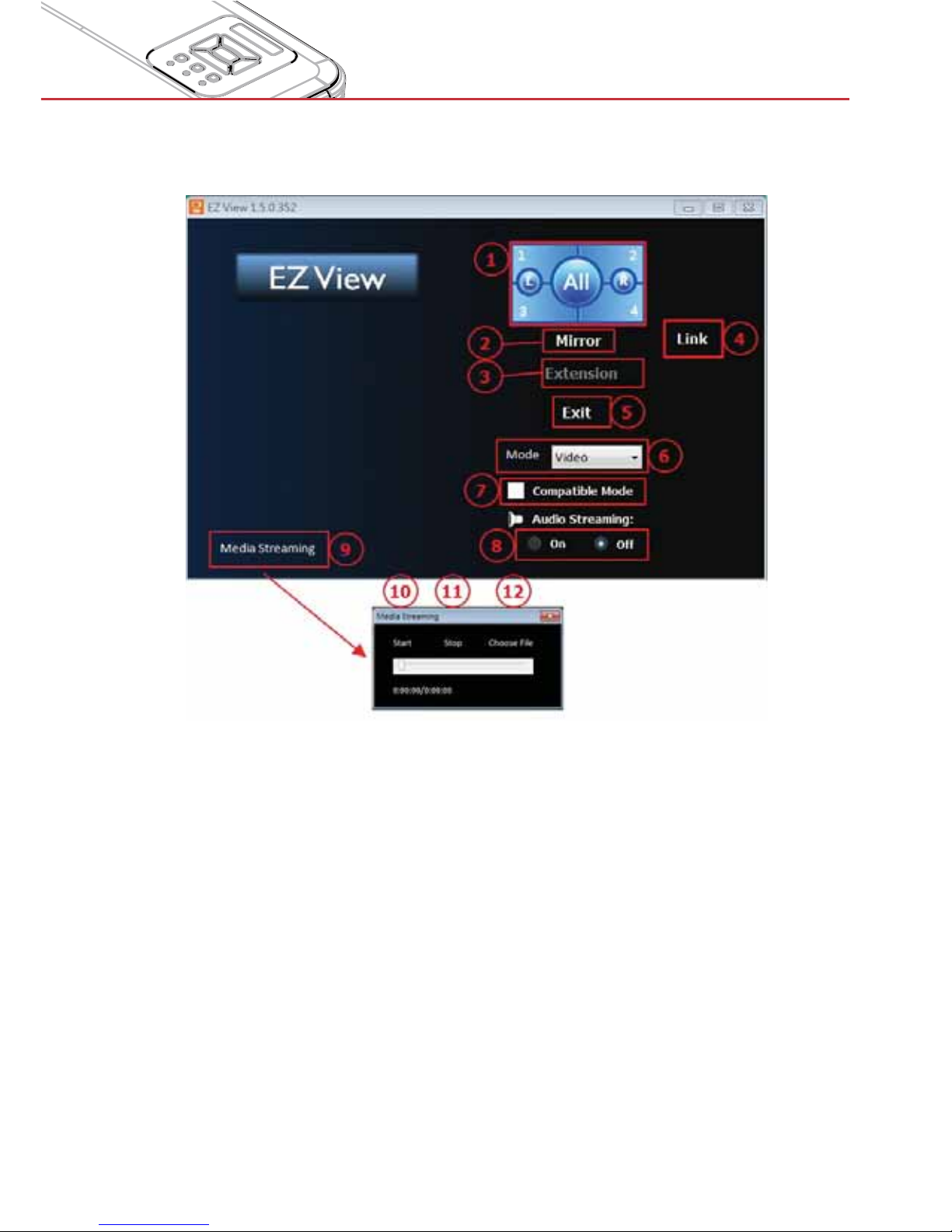
Step 4: For screen display function, select mirror mode or extension mode to project the
image from the device.
The selection of image position (1/4, 1/2 or 1/1 of screen)1.
Mirror Mode Display2.
Extension Mode Display3.
Link to Web management page (AP mode and client mode via LAN network 4.
only)
Exit5.
Display Mode : Video or Graphic6.
Compatible Mode7.
Audio On/Off8.
Media Streaming mode for playing video application9.
Start playing video10.
Stop playing video11.
Choosing video streaming file12.
Page 56
56
Multimedia
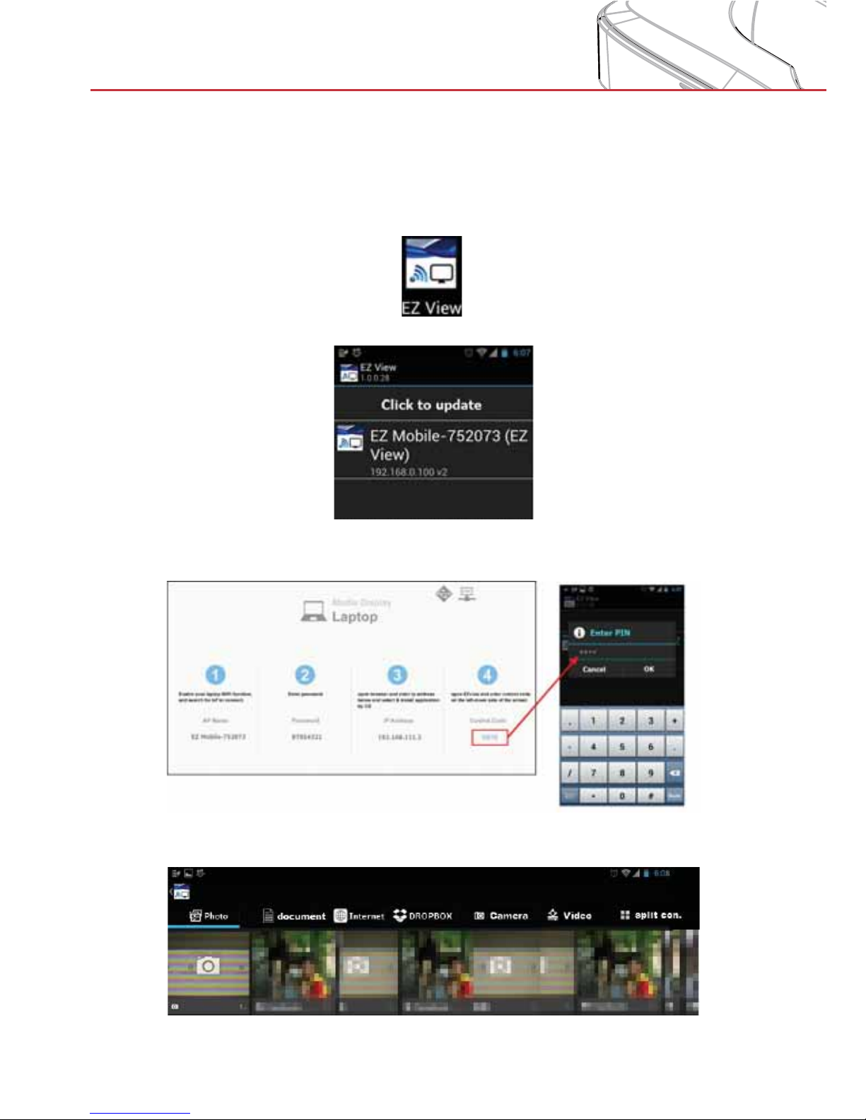
EZView on Tablet or Smart phone
Step 1: Connect your mobile/tablet to the projector (AP mode) or connect both the mobile/
tablet and the projector to a common WiFi or LAN network (Client mode).
Step 2: Start EZView on the device by clicking below icon on tablet or smart phone
Step 3: Start EZView APP and go to multimedia → mobile/tablet on the projector
Step 4: Enter the connection password shown on the screen.
Step 5: Select the way to stream to the projector via the EZView APP.
Page 57
57
Multimedia
Accessing Multimedia Files
This projector supports two methods to project media files (photos,
videos, music, documents) stored on following devices:
a. via Wireless dongle (see above) - wirelessly access the media files
stored on your mobile phone, tablet PC, notebook, or desktop.
b. via USB flash drive - directly access the media files stored on the
device.
How to access Multimedia mode
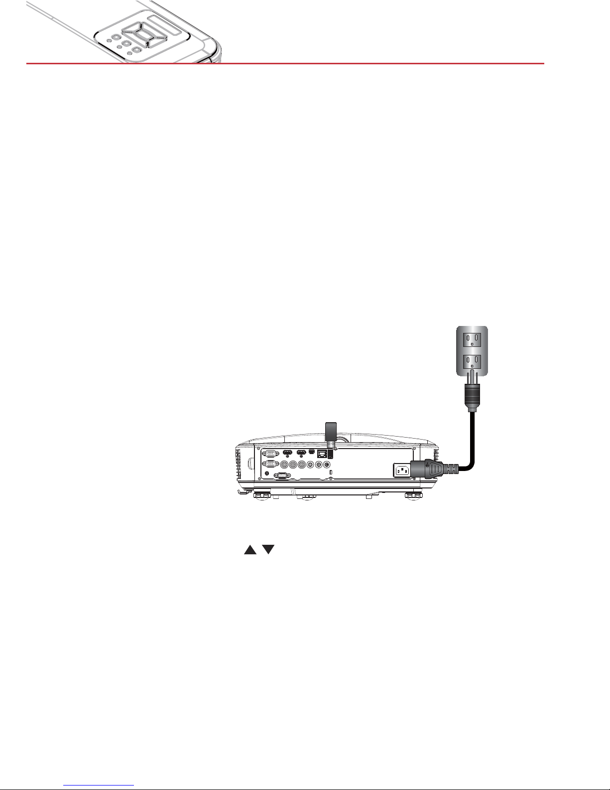
1. Plug a wireless dongle or a USB flash drive into the USB connector
at the back of the projector.
2. Turn on the projector.
E62405SP
R
3. Press “INPUT” on the remote control or on the control panel and
press the
keys to select “Multimedia” and the “Enter” key to
confirm.
Page 58
58
Multimedia
Mobile Display
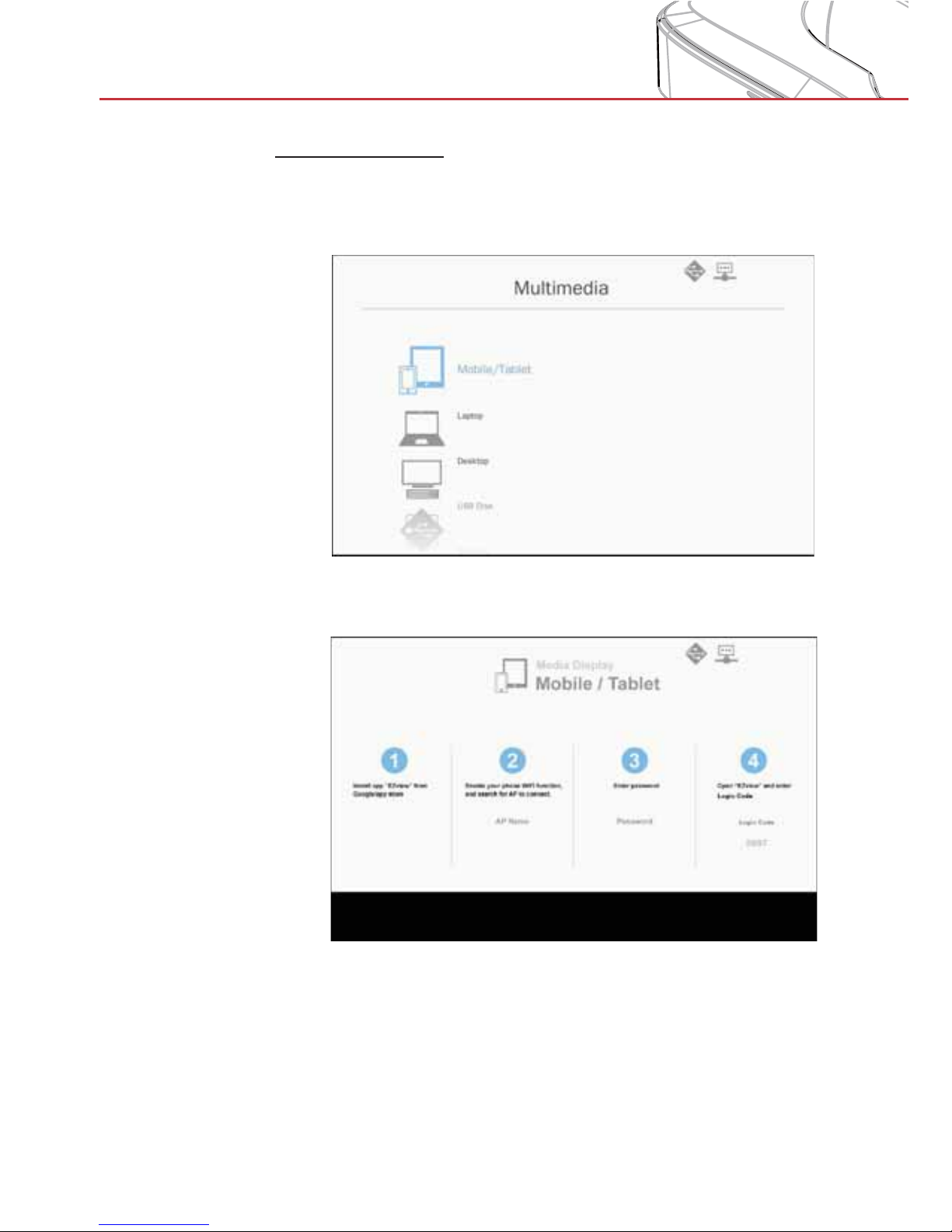
To access the media files stored on your mobile device or tablet
PC, do the folllowing:
1. In the Multimedia menu, select Mobile/Tablet.
2. On your mobile device or tablet PC: Install the “EZview”
application for your operating system.
3. Enable your mobile device or tablet PC WiFi function, and
search the AP name listed in the Wi-Fi network list.
4. On the initial connection, you will be prompted to enter a
password. Enter the password.
5. Launch the “EZview” application (see above) and enter the
login code.
6. Wait until the connection is established. The media files on your
mobile device or tablet PC can now be streamed to the the
projector.
Page 59
59
Multimedia
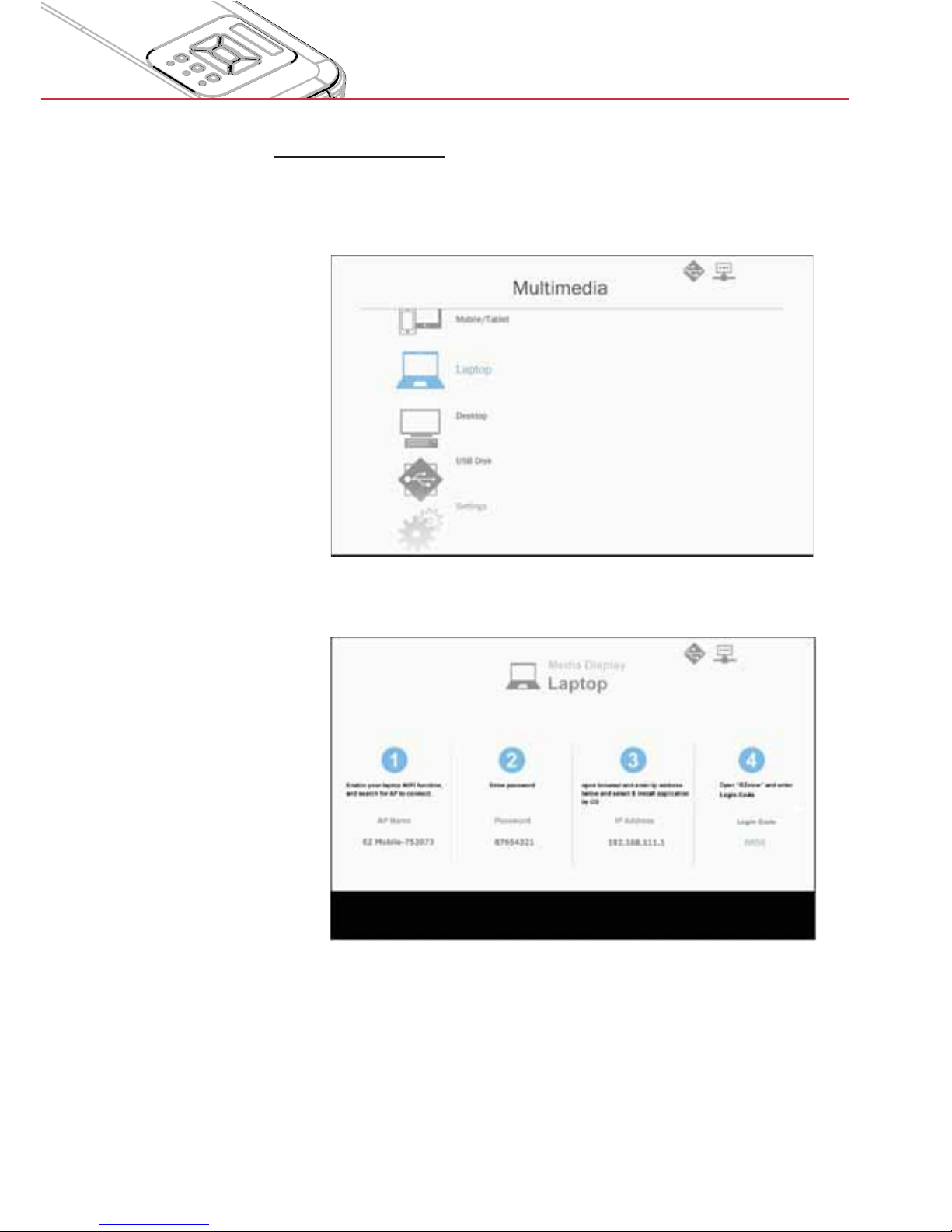
Laptop Display
To access the media files stored on your laptop/notebook, do the
folllowing:
1. In the Multimedia menu, select Laptop.
2. Enable your laptop/notebook WiFi function, and search the AP
name listed in the Wi-Fi network list.
3. At initial connection, you will be prompted to enter a password.
Enter the password.
4. Open your web browser and enter the IP address. Then select
“Wifi” on the left side of the screen and install the EZView
application for your operation system.
5. Launch the “EZview” application (see above) and enter the login
code.
Page 60
60
Multimedia
6. Wait until the connection is established. The media files on your
laptop/notebook can now be streamed to the projector.
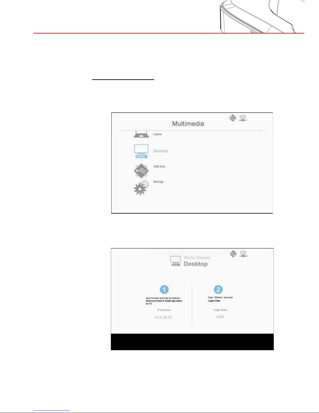
Desktop Display
To access the media files stored on your desktop, do the
folllowing:
1. In the Multimedia menu, select Desktop.
2. Open your web browser and enter the IP address displayed on
the screen. Then select “Wifi” on the left side of the screen and
install the EZView application for your operation system.
Page 61
61
Multimedia
3. Launch the “EZview” application (see above) and enter the
login code.
4. Wait until the connection is established. The media files on your
desktop can now be streamed to the projector.
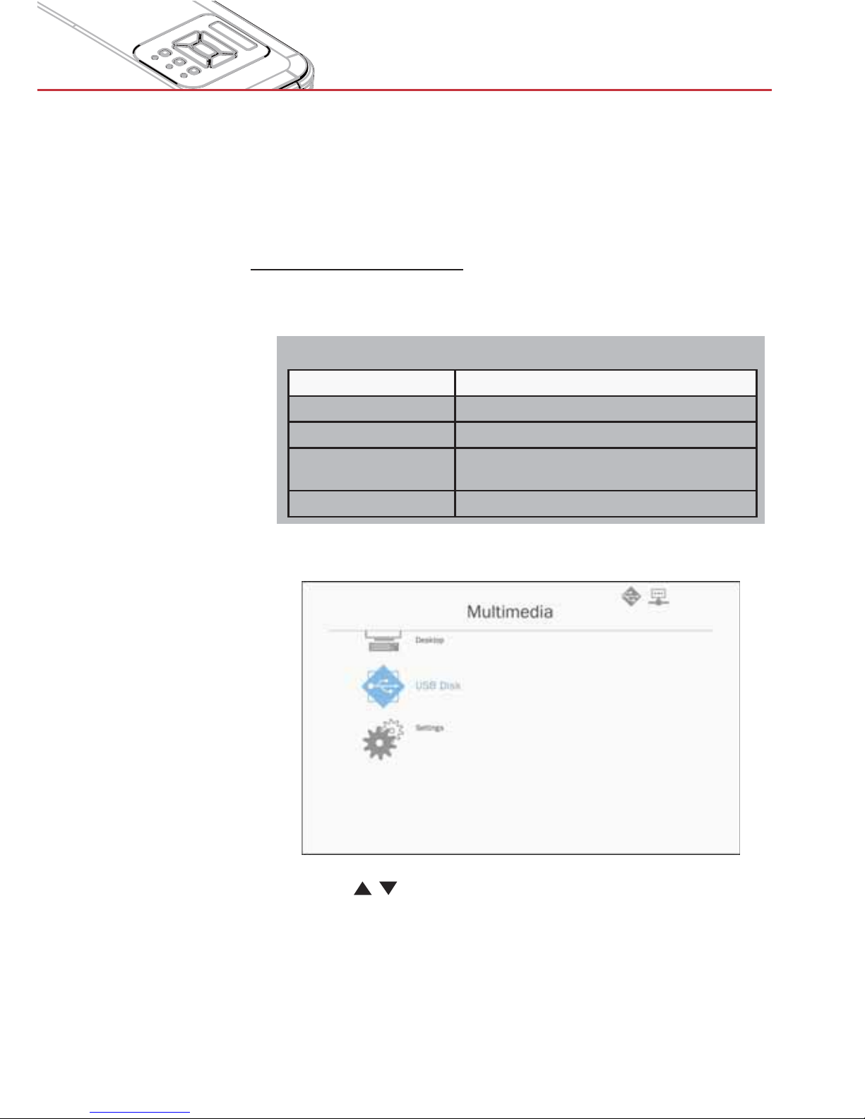
USB Storage Display
To access the media files stored on your USB flash drive, do the
folllowing:
Supported File Formats
Multimedia Category File Formats
Photo BMP, JPG
Music MP3, WMA
Video AVI, MOV, MP4, RM, RMVB, DAT, MPG,
ISO, TS, MKV, VOB, and WMV
Document WORD, EXCEL, PPT, PDF
1. In the Multimedia menu, select USB Disk.
2. Use the
keys to select the file category and press the
“Enter” key.
Page 62
62
Multimedia
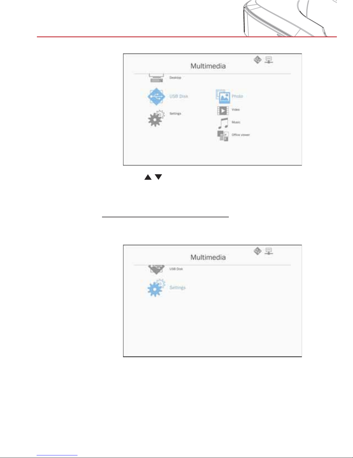
3. Use the
keys to select the file to view/play and press the
“Enter” key to confirm.
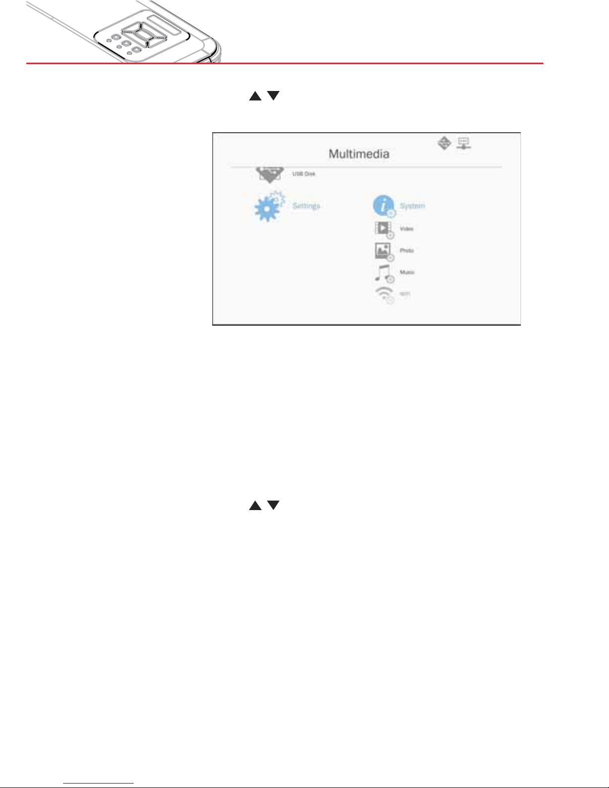
Configuring Multimedia Settings
To ch ang e the set tin gs, do the folllowing:
1. In the Multimedia menu, select Settings.
Page 63
63
Multimedia
2. Use the
keys to select the desired menu option and
press the “Enter” key to enter the submenu.
>
System: Select this option to view the firmware version and
update firmware.
>
Video: Select this option to change the display ratio and set
the repeat mode.
>
Photo: Select this option to change the display ratio,
slideshow pattern, and slideshow duration.
>
Music: Select this option to set the repeat mode .
>
WiFi: Select this option to configure the Wi-Fi connection.
3. Use the
keys to select the adjust/select the setting and
press the “Enter” key to confirm.
Page 64
64
Appendices
Installing and Cleaning the Optional
Dust Filter
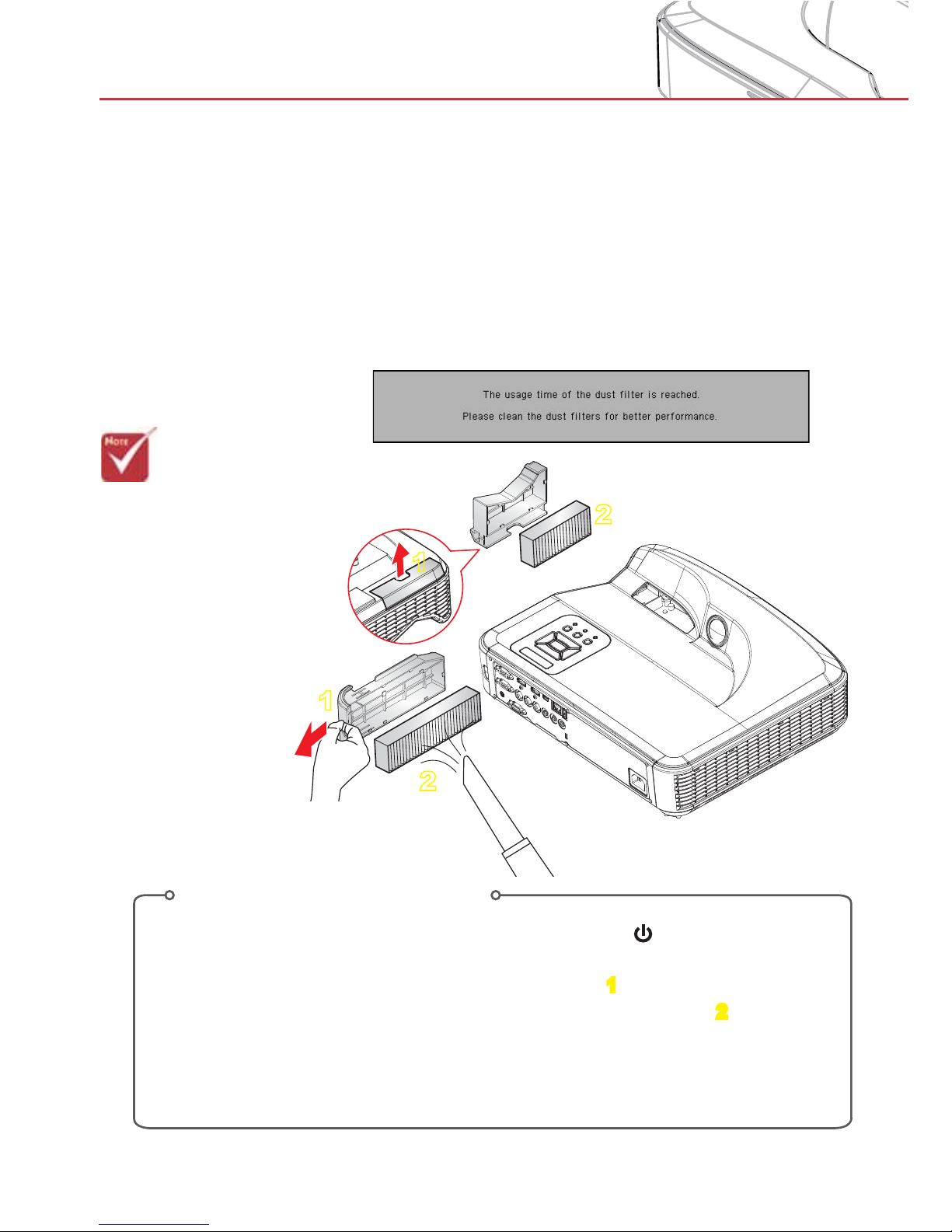
We recommend you clean the dust filter every 500 hours of
operation, or more often if you are using the projector in a
dusty environment.
When the warning message appears on the screen, do the
following to clean the air filter:
>The optional dust
filter should be
used in dusty
environments.
>If the dust filter is
installed proper
maintenance will
prevent overheating and projector
malfunction.
>The dust filter is
optional.
Air Filter Cleaning Procedure:
1. Switch off the power to the projector by pressing the “ ” button.
2. Disconnect the power cord.
3. Pull out the dust filter, as shown in the illustration.
1
4. Carefully remove the dust filter. Then clean or change the filter.
2
To install the filter, reverse the previous steps.
5. Turn on the projector and reset the filter usage counter after the dust filter is
replaced.
1
1
2
2
Page 65
65
Appendices
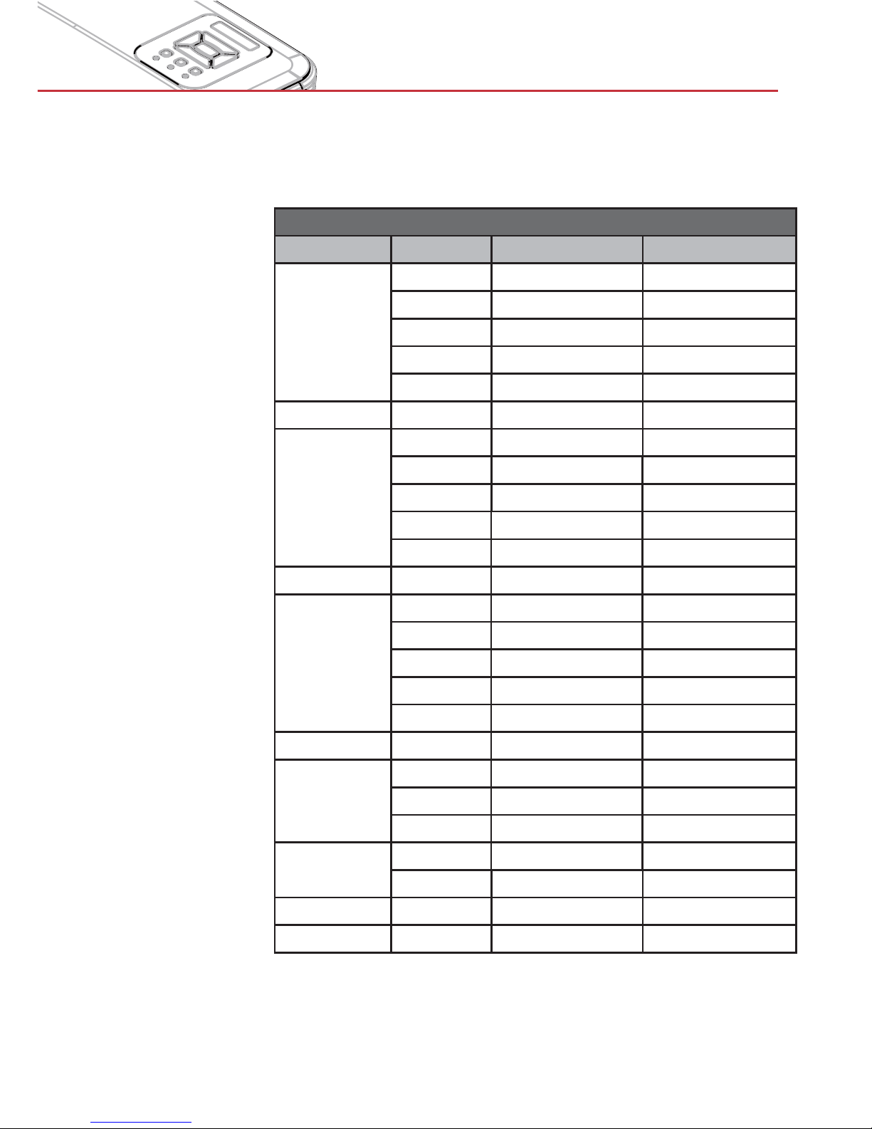
Compatibility Modes
> VGA Analog
a. PC signal
Modes Resolution V. Frequency [Hz] H. Frequency [Hz]
VGA
640x480 60 31.5
640x480 67 35.0
640x480 72 37.9
640x480 75 37.5
640x480 85 43.3
IBM 720x400 70 31.5
SVGA
800x600 56 35.1
800x600 60 37.9
800x600 72 48.1
800x600 75 46.9
800x600 85 53.7
Apple, MAC II 832x624 75 49.1
XGA
1024x768 60 48.4
1024x768 70 56.5
1024x768 75 60.0
1024x768 85 68.7
1024x768 120 99.0
Apple, MAC II 1152x870 75 68.7
SXGA
1280x1024 60 64.0
1280x1024 72 77.0
1280x1024 75 80.0
QuadVGA
1280x960 60 60.0
1280x960 75 75.2
SXGA+ 1400x1050 60 65.3
UXGA 1600x1200 60 75.0
Page 66
66
Appendices
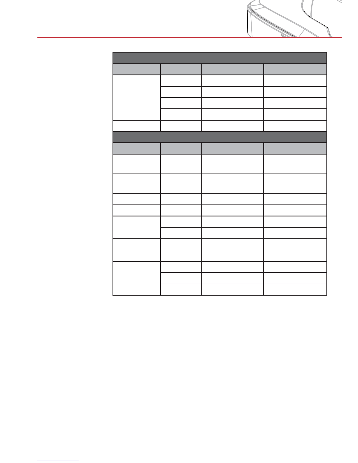
b. Extended wide timing
Modes Resolution V. Frequency [Hz] H. Frequency [Hz]
WXGA
1280x720 60 44.8
1280x800 60 49.6
1366x768 60 47.7
1440x900 60 59.9
WSXGA+ 1680x1050 60 65.3
c. Component signal
Modes Resolution V. Frequency [Hz] H. Frequency [Hz]
480i
720x480
(1440x480)
59.94(29.97) 15.7
576i
720x576
(1440x576)
50(25) 15.6
480p 720x480 59.94 31.5
576p 720x576 50 31.3
720p
1280x720 60 45.0
1280x720 50 37.5
1080i
1920x1080 60(30) 33.8
1920x1080 50(25) 28.1
1080p
1920x1080 23.98/24 27.0
1920x1080 60 67.5
1920x1080 50 56.3
Page 67
67
Appendices
> HDMI Digital
a. PC signal
Modes Resolution V. Frequency [Hz] H. Frequency [Hz]
VGA
640x480 60 31.5
640x480 67 35.0
640x480 72 37.9
640x480 75 37.5
640x480 85 43.3
IBM 720x400 70 31.5
SVGA
800x600 56 35.1
800x600 60 37.9
800x600 72 48.1
800x600 75 46.9
800x600 85 53.7
Apple, MAC II 832x624 75 49.1
XGA
1024x768 60 48.4
1024x768 70 56.5
1024x768 75 60.0
1024x768 85 68.7
1024x768 120 99.0
Apple, MAC II 1152x870 75 68.7
SXGA
1280x1024 60 64.0
1280x1024 72 77.0
1280x1024 75 80.0
QuadVGA
1280x960 60 60.0
1280x960 75 75.2
SXGA+ 1400x1050 60 65.3
UXGA 1600x1200 60 75.0
Page 68
68
Appendices
b. Extended wide timing
Modes Resolution V. Frequency [Hz] H. Frequency [Hz]
WXGA
1280x720 60 44.8
1280x800 60 49.6
1366x768 60 47.7
1440x900 60 59.9
WSXGA+ 1680x1050 60 65.3
c. Video signal
Modes Resolution V. Frequency [Hz] H. Frequency [Hz]
480p 640x480 59.94/60 31.5
480i
720x480
(1440x480)
59.94(29.97) 15.7
576i
720x576
(1440x576)
50(25) 15.6
480p 720x480 59.94 31.5
576p 720x576 50 31.3
720p
1280x720 60 45.0
1280x720 50 37.5
1080i
1920x1080 60(30) 33.8
1920x1080 50(25) 28.1
1080p
1920x1080 23.98/24 27.0
1920x1080 60 67.5
1920x1080 50 56.3
d. HDMI 1.4a mandatory 3D timing- Video Signal
Modes Resolution V. Frequency [Hz] H. Frequency [Hz]
Frame
Packing
720p 50 31.5
720p 59.94/60 15.7
1080p 23.98/24 15.6
Side-by-
Side(Half)
1080i 50 31.5
1080i 59.94/60 31.3
Top and
Bottom
720p 50 45.0
720p 59.94/60 37.5
1080p 23.98/24 33.8
Page 69
69
Appendices
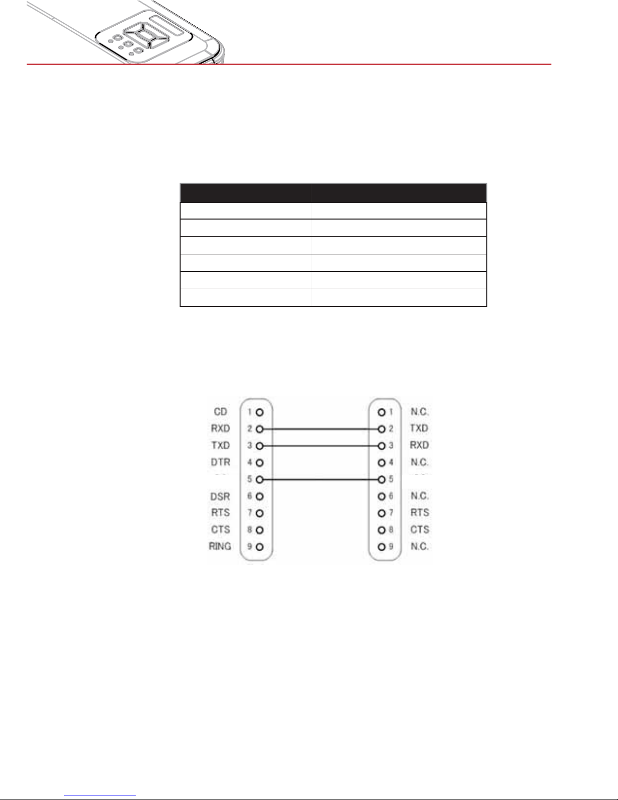
RS232 Port Settings
Items Method
Communication Method Asynchronous Communication
Bits per seconds
19200
Data bits 8 bits
Parity None
Stop bits 1
Flow control None
RS232 Signals Connection
SGND SGND
RS232 Commands and Protocol
Function List
Computer COM Port
(D-Sub 9pin connector)
Projector COM Port
(D-Sub 9pin connector)
>
>
Page 70
70
Appendices
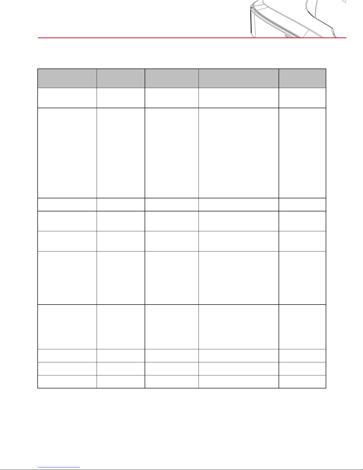
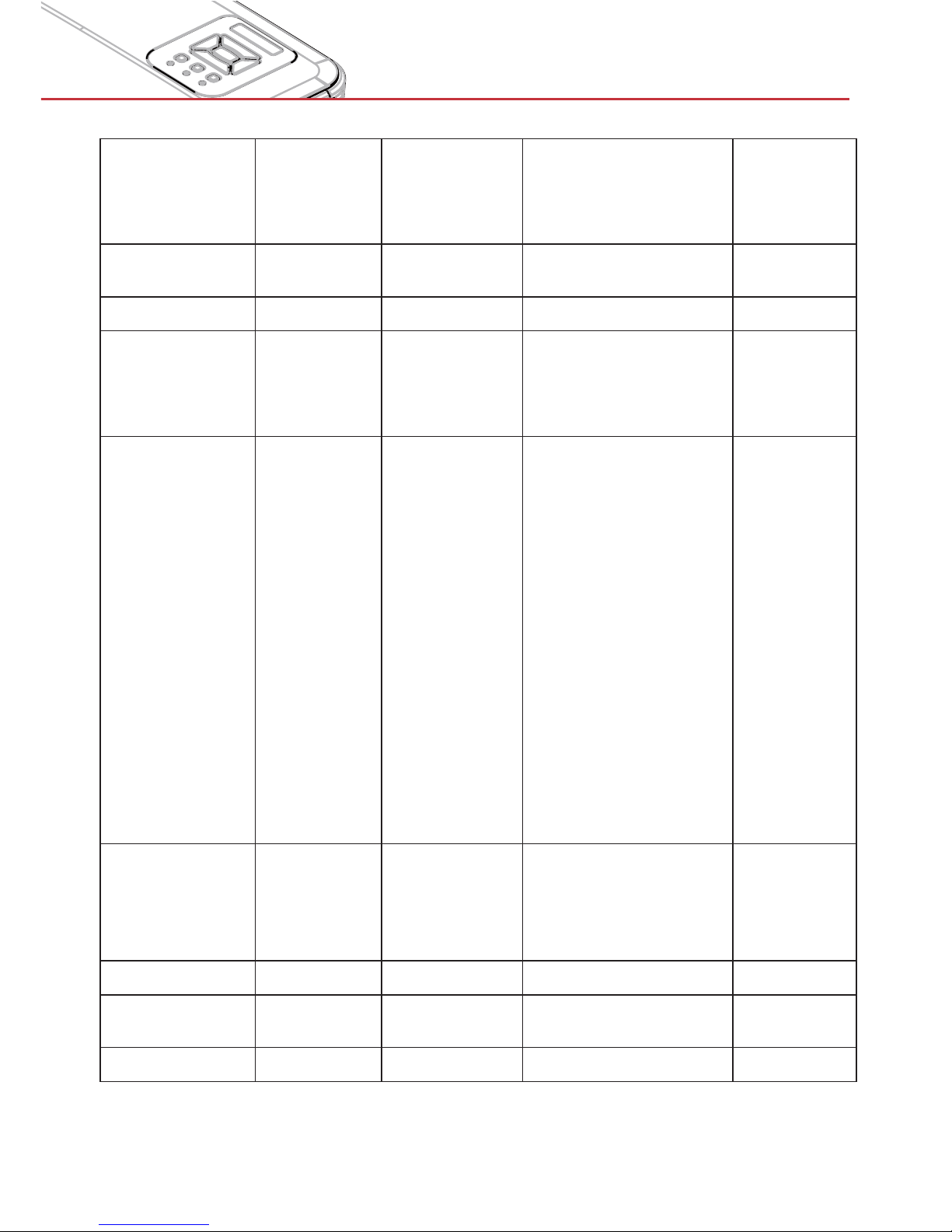
Commands Set List
Command
Description
ASCII Code
Projector
Return
n value Note
Power #0000 n
0 : Off
1 : On
Emulate Remote #0001 n
1 : Up
2 : Left
3 : Right
4 : Down
5 : Menu
6 : Source
7 : Keystone+
8 : Keystone9 : Volume+
10 : Volume-
Resync #0002 1
VGA only
AV Mute (Blank) #0003 n
0 : Off
1 : On
Freeze #0004 n
0 : Unfreeze
1 : Freeze
Input Source #0005 n
1 : VGA 1
2 : VGA 2
3 : HDMI 1
4 : HDMI 2
5 : Video
6 : Multimedia
Color Mode #0010 n
1 : Bright
2 : PC
3 : Movie
4 : Game
5 : User
Brightness #0011 n 0~100
Contrast #0012 n 0~100
Sharpness #0013 n 0~31 Video only
>
Page 71
71
Appendices
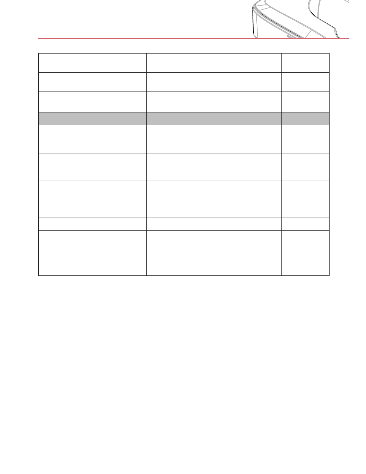
Aspect Ratio #0020 n
1 : Auto
2 : 4:3
3 : 16:9
4 : 16:10
Zoom #0021 n
0 : Zoom1 : Zoom+
Keystone #0022 n -40~40
Orientation #0023 n
1 : Front
2 : Rear
3 : Front Ceiling
4 : Rear Ceiling
Language #0030 n
1 : English
2 : German
3 : Swedish
4 : French
5 : Arabic
6 : Dutch
7 : Norwegian
8 : Danish
9 : Simplified Chinese
10 : Polish
11 : Korean
12 : Russian
13 : Spanish
14 : Traditional Chinese
15 : Italian
16 : Portuguese
17 : Turkish
18 : Japanese
Menu Location #0031 n
1 : Top Left
2 : Top Right
3 : Center
4 : Bottom Left
5 : Bottom Right
Reset #0032 1
Mute #0040 n
0 : Off
1 : On
Volume #0041 n 0~30
Page 72
72
Appendices
Microphone
Volume
#0042 n 0~30
Auto Power Off
(min)
#0050 n 0~120 Step = 5
High Altitude #0051 n
0 : Off
1 : On
Color Mode
Read
#00110 1 Okn
n : 1/2/3/4/5 = Bright
/ PC / Movie / Game /
User
Aspect Ratio
Read
#00120 1 Okn
n : 1/2/3/4 = Auto / 4:3
/ 16:9 / 16:10 (Ultra
Wide)
Input Source
(curr. src)
#00160 1 Okn
n : 0/1/2/3/4/5/6 =
None / VGA1 / VGA2 /
HDMI1 / HDMI2 / Video
/ Multimedia
Sofware Version #00161 1 Okddd ddd : FW version
Information #00162 1
Okabbbbccdddee
a : Power Status / b
: LD Hour / c : Input
Source / d : Firmware
Version / e : Color
mode
Page 73
73
Appendices
Crestron
User can control the projector via Crestron flash UI.
Based on Crestron flash UI for the input-string in [tools] tab, the
limitation for Input-Length is in the below list (“space” and the other
punctuation key included):
Category Item Input-Length (characters)
Crestron Control
IP Address 15
IP ID 2
Port 5
Projector
Projector Name 10
Location 9
Assigned To 9
Network
Configuration
DHCP (Enabled) (N/A)
IP Address 15
Subnet Mask 15
Default Gateway 15
DNS Server 15
User Password
Enabled (N/A)
New Password 15
Confirm 15
Admin Password
Enabled (N/A)
New Password 15
Confirm 15
Page 74
74
Appendices
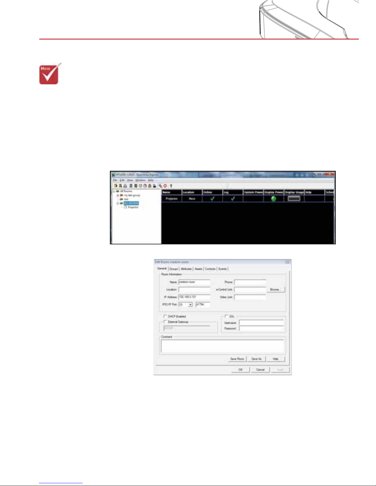
Crestron RoomView Control Tool
Crestron RoomView™ provides a central monitoring station for 250+
control systems on a single Ethernet network (more are possible,
the number depends on the combination of IP ID and IP address).
Crestron RoomView monitors each projector, including projector’s
online status, system power, lamp life, network setting and hardware
faults, plus any custom attribute as defined by the Administrator.
The Administrator can add, delete, or edit room information, contact
information and events, which are logged automatically by the
software for all users. (Operation UI as following image)
1. Main Screen
2. Edit Room
>Crestron Room-
View’s function is
set according to the
products’ models
and specifications.
Page 75
75
Appendices
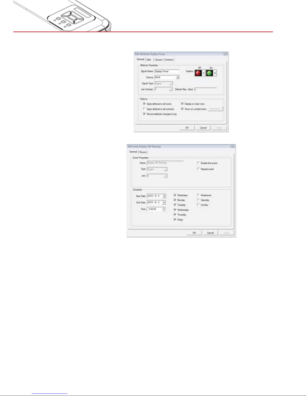
3. Edit Attribute
4. Edit Event
For further information, please visit:
http://www.crestron.com & www.crestron.com/getroomview.
Page 76
76
Appendices
> Please note that
damage resulting
from incorrect
installation will void
the warranty.
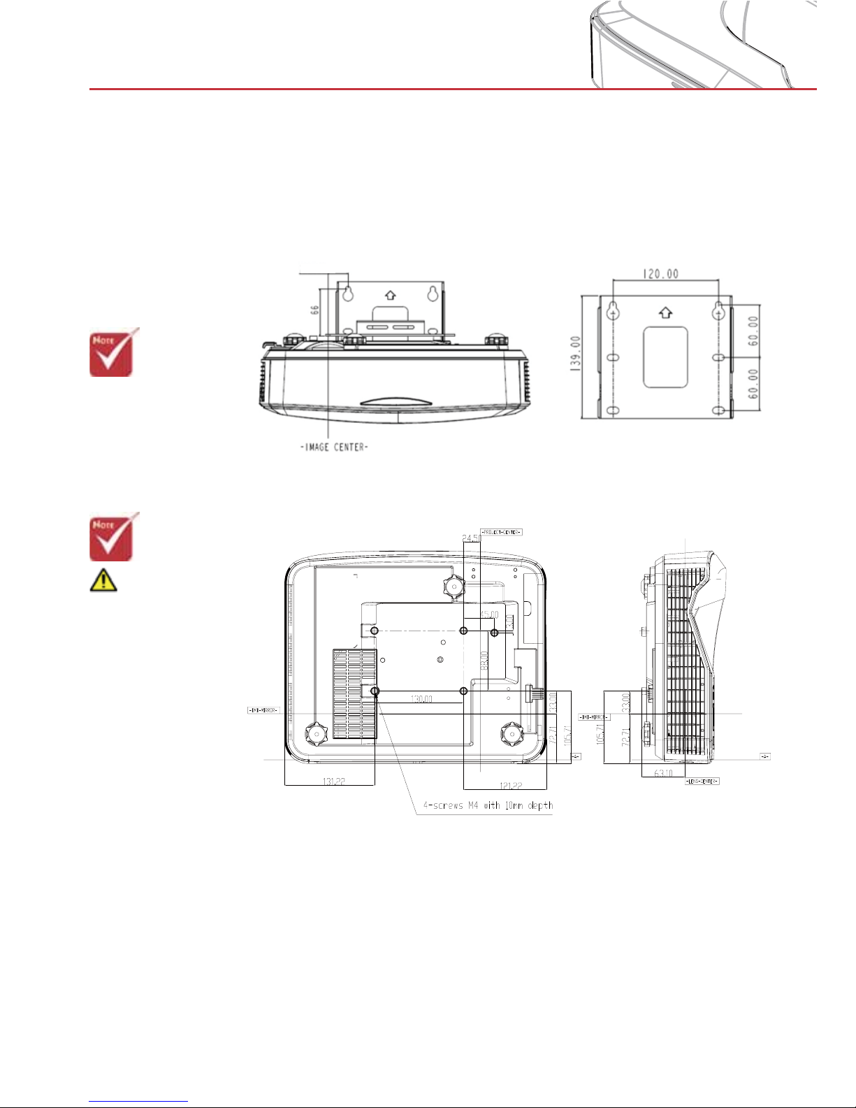
Ceiling Mount Installation
For ceiling mount operation use the dnp LaserPanel mount.
Warning:
1. Be sure to keep
at least 10 cm gap
between the ceiling
and the bottom of the
projector.
2. Avoid installing the
projector near a heat
source.
3 0 . 0 0
Page 77
77
Appendices
Trouble-shooting
Q1 Why can the PC not boot when connected to the projector by
the USB cable?
A:
1. Unplug USB cable from PC; or
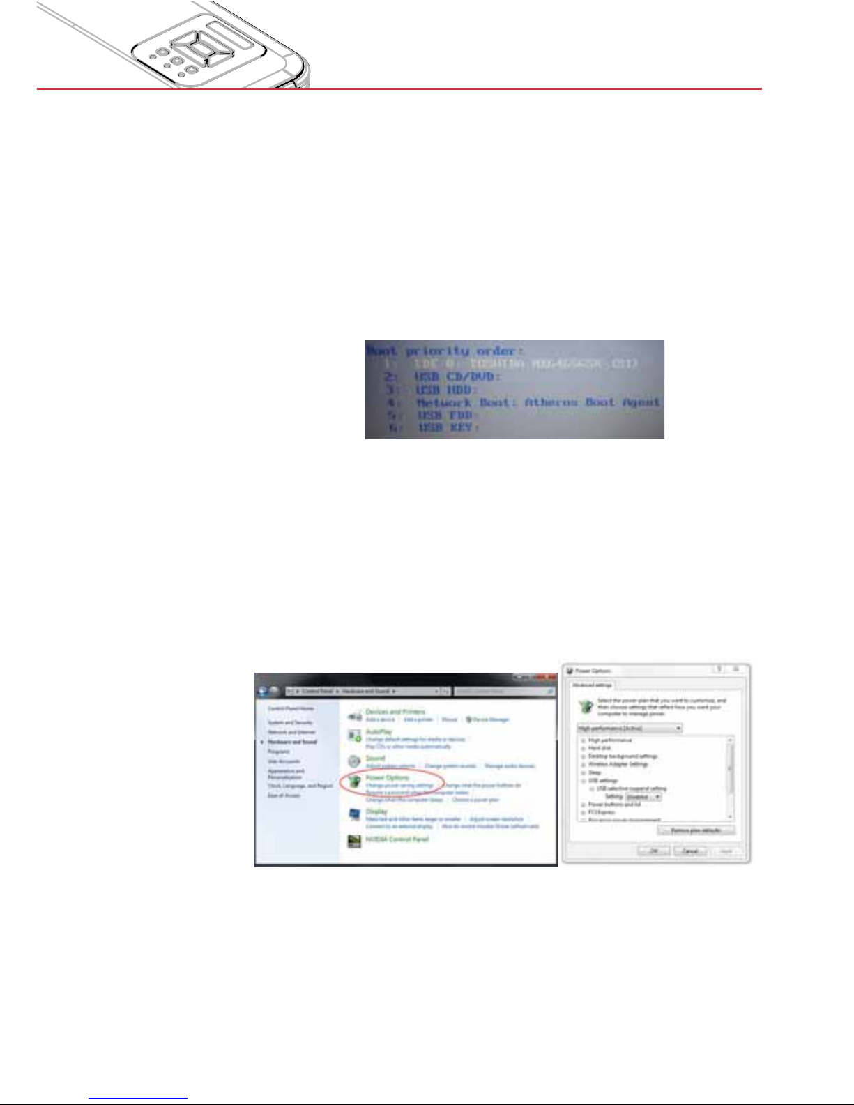
2. Go to BIOS setup page of PC and modify the “Boot priority
order.” Choose Hard disk as top priority, save the change
and reboot PC.
Q2 What to do when the operating system cannot identify the USB
device?
A:
1. Unplug/re-plug in the USB cable and check again.
2. Switch to another USB port and check again.
3. Restart your computer and check again.
4. Go to Power Options in the Control Panel, check the USB
selective suspend settings status in USB settings under
Advance Settings. Switch to “Disabled”.
5. Go to the official website of the laptop/PC manufacturer, and
update the USB driver to the latest version.
6. Use the USB cable included with your projector and check
again. If an USB extension is needed, please contact your
distributor.
Page 78
78
Appendices
7. The USB port of your computer may not work properly.
Please contact your IT staff.
Q3 Why is the utility icon red (
), not green ( /
)?
A: A red icon (
) indicates a failed connection. This may be
caused by the following:
1. Check if the interactive function is enabled in the OSD.
2. Unplug/re-plug in the USB cable and check again.
3. Switch to another USB port and check again.
4. Restart your computer and check again.
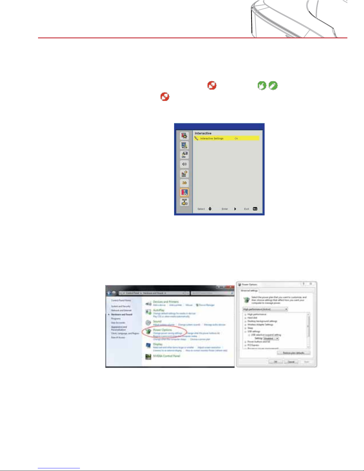
5. Go to Power Options in Control Panel; check the USB selective suspend settings status in USB settings under Advance
Settings. Switch to “Disabled”.
6. Go to the official website of the laptop/PC manufacturer, and
update the USB driver to the latest version.
7. Go to the official website of the laptop/PC manufacturer, and
update the BIOS driver to the latest version.
Page 79
79
Appendices
8. Use the USB cable included with your projector and check
again. If an USB extension is needed, please contact your
distributor.
9. The USB port of your computer may not work properly.
Please contact your IT staff.
Q4 What to do when there is only single touch point?
A:
1. Re-plug USB cable from PC.
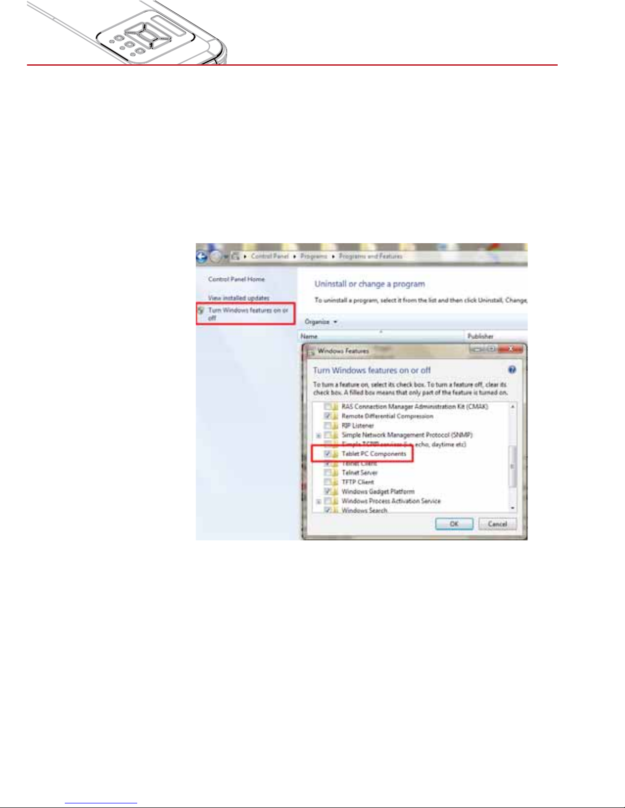
2. Go to “Control Panel” and make sure “Tablet PC Components” is selected.
Q5 When should Calibration and Touch Area Setting be done?
A: Please perform Calibration and Touch Area setting during first
installation. If projector or screen is moved, Touch Area Setting
and Calibration should be performed again.
- When Laptop/PC resolution is changed, calibrate again.
- For better accuracy, please do Manual Calibration.
- If an overlarge offset is observed, please perform Manual
Calibration and see Step 5 Calibration for troubleshooting.
Q6 What to do when Auto Calibration and Auto Touch Area Setting
both failed?
Page 80
80
Appendices
A:
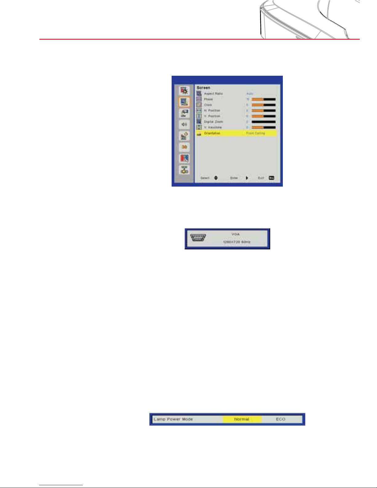
1. Check “orientation” OSD setting first. The interactive function
supports Ceiling Mode only
When a projector OSD message is shown, this may result in failure
to Auto Calibrate and Auto Touch Area Setting. Wait until the OSD
message disappears before performing Auto Calibration and Auto
Touch Area Setting.
Please follow below trouble-shooting steps to perform Auto Calibration and Auto Touch Area Setting again.
a. Quit all software applications
b. Reduce ambient light
c. Do not obstruct or shake the lens during Calibration
d. Check if the projected image is clear. If not, adjust the
focus to sharpen the image.
e. If the “Auto Touch Area Setting failed” or the “Auto Cali-
bration failed” messages pop up on the screen again,
switch to Manual Mode for Touch Area Setting and Calibration.
2. Check the Projector Lamp Power Mode selection. Lower
lamp brightness (ECO mode) may affect both Auto Touch
Area Setting and Auto Calibration. Switch to Normal mode to
complete Touch Area Setting and Calibration.
Page 81
81
Appendices
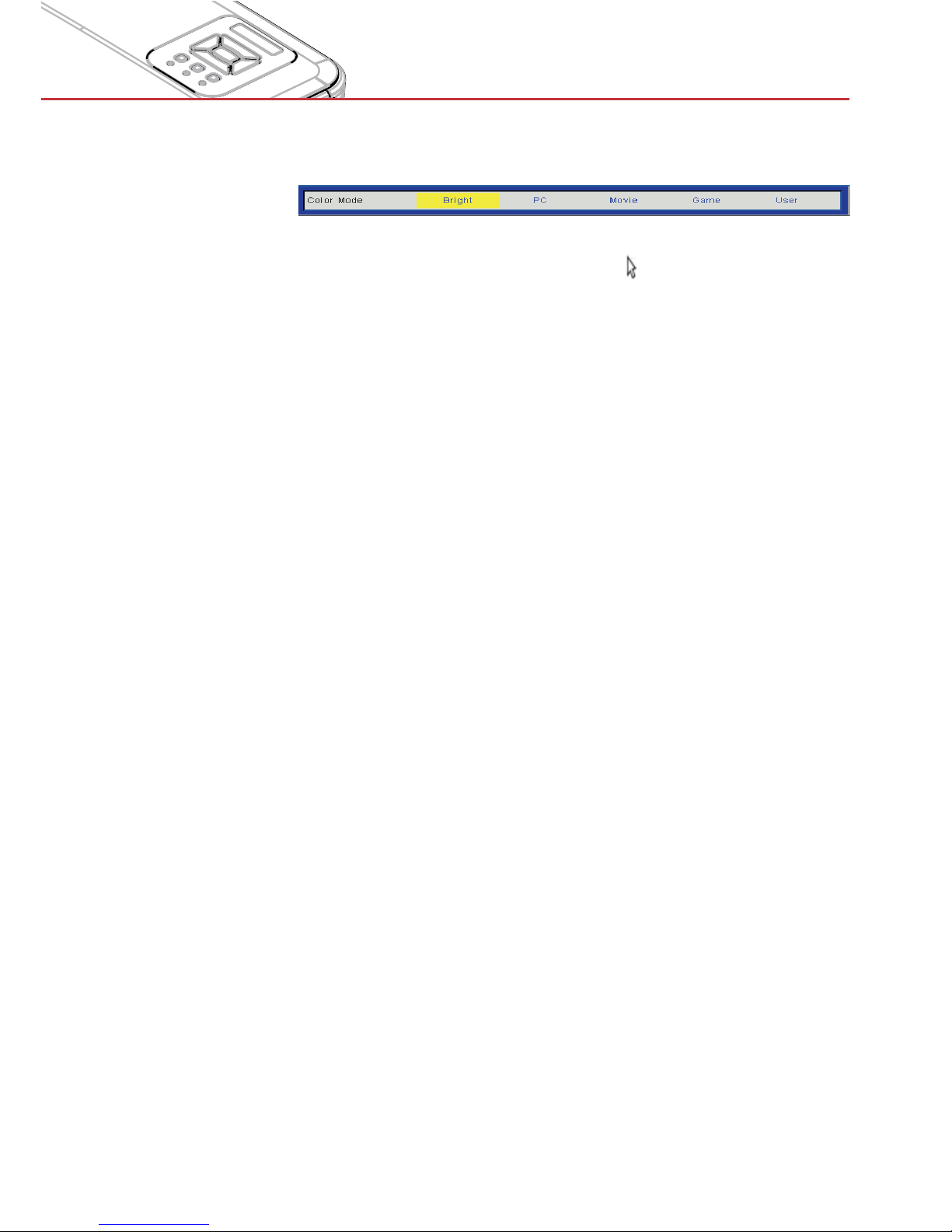
3. Check the Projector Color Mode selection. To ensure accuracy of both Auto Touch Area Setting and Auto Calibration,
it is suggested to switch Color mode to Bright Mode.
Q8 What to do when the mouse cursor ( ) flashes or jumps on
the screen, or when the Touch function does not work well at a
certain projection area?
A:
1. Check if there is strong light shown on the screen. If yes,
turn off the light.
2. Check if there is any foreign objects on the screen. If yes,
remove the object.
3. Refer to Step 4 Touch Area Setting for detailed procedures,
check if the Manual Touch Area frame is set properly.
Q9 What to do when the projection area corner is insensitive or
intermittent lines are observed?
A:
1. Adjust the level of Touch Sensitivity to enhance sensitivity,
see Step 6 Touch Sensitivity for trouble-shooting.
2. If the Touch function remains insensitive, check the camera
lens condition. If dust or particles are observed, gently clean
the optical port with dust blower.
Q10 What to do when the Touch function is not accurate?
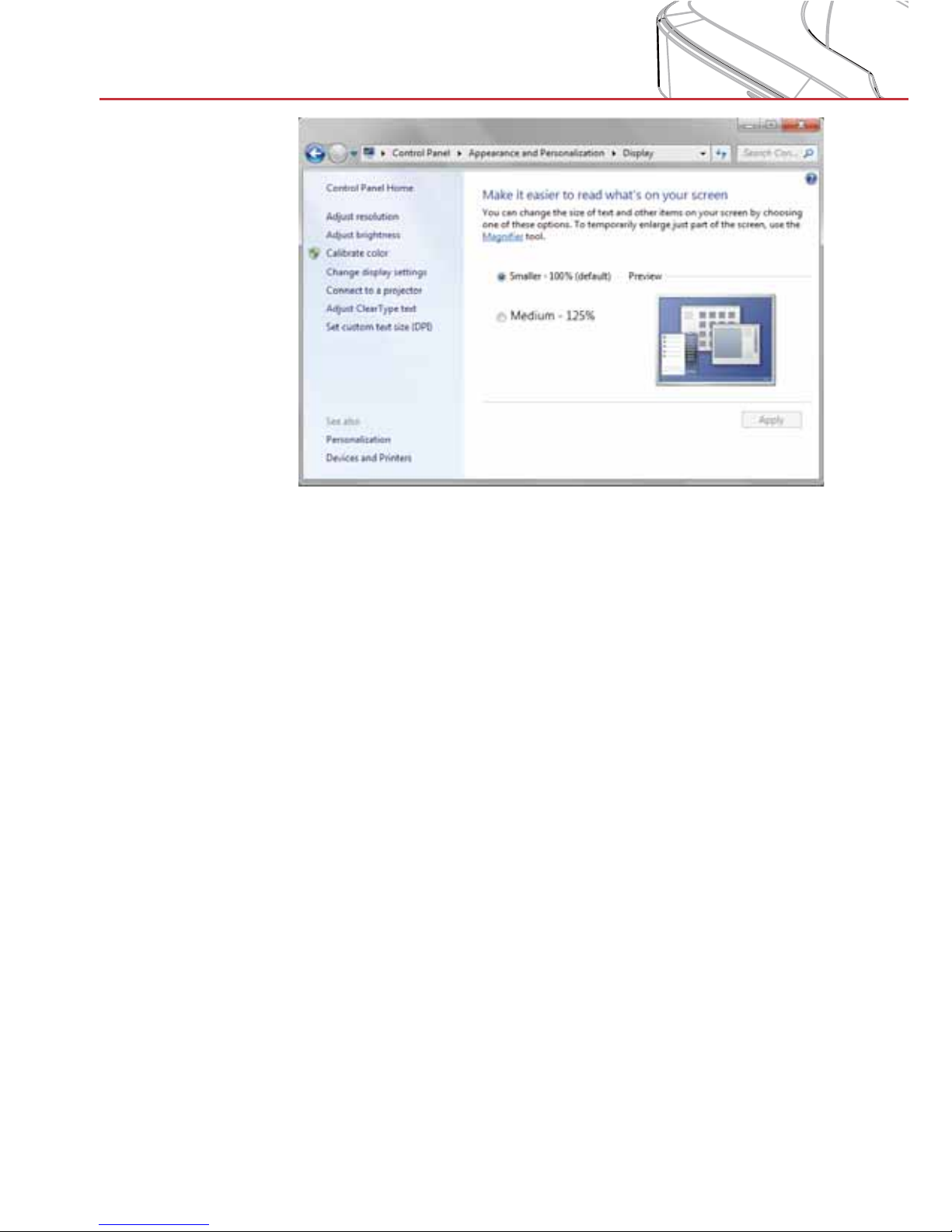
A: Touch accuracy may be impacted when Windows default dis-
play setting under Windows has been changed.
1. Go to the setting page <Start menu/Control Panel/Appearance and Personalization>
Page 82
82
Appendices
2. Select “Smaller - 100%(Default) ” and click “Apply”.
Page 83
83
Appendices
Regulation & Safety Notices
This appendix lists the general notices of your projector.
FCC notice
This device has been tested and found to comply with the
limits for a Class B digital device pursuant to Part 15 of the
FCC rules. These limits are designed to provide reasonable
protection against harmful interference in a residential
installation. This device generates, uses and can radiate radio
frequency energy and, if not installed and used in accordance
with the instructions, may cause harmful interference to radio
communications.
However, there is no guarantee that interference will not
occur in a particular installation. If this device does cause
harmful interference to radio or television reception, which can
be determined by turning the device off and on, the user is
encouraged to try to correct the interference by one or more of
the following measures:
>
Reorient or relocate the receiving antenna.
>
Increase the separation between the device and
receiver.
>
Connect the device into an outlet on a circuit different
from that to which the receiver is connected.
>
Consult the dealer or an experienced radio/television
technician for help.
Notice: Shielded cables
All connections to other computing devices must be
made using shielded cables to maintain compliance with
FCC regulations.
Caution
Changes or modifications not expressly approved by the
manufacturer could void the user’s authority, which is
granted by the Federal Communications Commission, to
operate this projector.
Page 84
84
Appendices
Disposal instructions
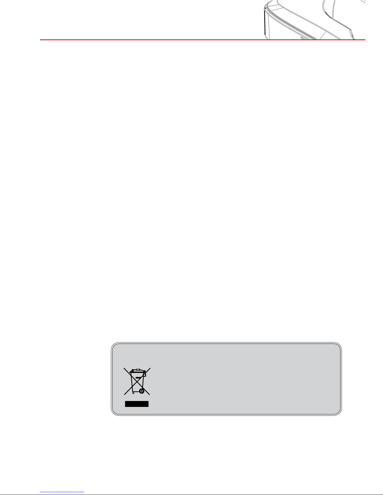
Do not throw this electronic device into the
trash when discarding. To minimize pollution
and ensure utmost protection of the global
environment, please recycle it.
Operation conditions
This device complies with Part 15 of the FCC Rules. Operation
is subject to the following two conditions:
1. This device may not cause harmful interference and
2. This device must accept any interference received,
including interference that may cause undesired
operation.
Notice: Canadian users
This Class B digital apparatus complies with Canadian
ICES-003.
Remarque à l’intention des utilisateurs
canadiens
Cet appareil numerique de la classe B est conforme a la
norme NMB-003 du Canada.
Declaration of Conformity for EU
countries
• EMC Directive 2004/108/EC (including amendments)
• Low Voltage Directive 2006/95/EC
• R & TTE Directive 1999/5/EC (if product has RF function)
Page 85
85
Appendices
7KLVSURMHFWRULVD&ODVVODVHUGHYLFHWKDWFRQIRUPV
ZLWK,(&&)5DQG
,(&/RZ5LVN*URXS
7KLVSURMHFWRUKDVEXLOWLQ&ODVVODVHUPRGXOH'LVDVVHPEO\
RUPRGLILFDWLRQLVYHU\GDQJHURXVDQGVKRXOGQHYHUEH
DWWHPSWHG
$Q\RSHUDWLRQRUDGMXVWPHQWQRWVSHFLILFDOO\LQVWUXFWHGE\WKH
XVHU¶VJXLGHFUHDWHVWKHULVNRIKD]DUGRXVODVHUUDGLDWLRQ
H[SRVXUH
'RQRWRSHQRUGLVDVVHPEOHWKHSURMHFWRUDVWKLVPD\FDXVH
GDPDJHE\WKHH[SRVXUHRIODVHUUDGLDWLRQ
'RQRWVWDUHLQWREHDPZKHQWKHSURMHFWRULVRQ7KHEULJKW
OLJKWPD\UHVXOWLQSHUPDQHQWH\HGDPDJH
:LWKRXWIROORZLQJWKHFRQWURODGMXVWPHQWRURSHUDWLRQ
SURFHGXUHPD\FDXVHGDPDJHE\WKHH[SRVXUHRIODVHU
UDGLDWLRQ
$GHTXDWHLQVWUXFWLRQVIRUDVVHPEO\RSHUDWLRQDQG
PDLQWHQDQFHLQFOXGLQJFOHDUZDUQLQJVFRQFHUQLQJSUHFDXWLRQV
WRDYRLGSRVVLEOHH[SRVXUHWRODVHUDQGFROODWHUDOUDGLDWLRQLQ
H[FHVVRIWKHDFFHVVLEOHHPLVVLRQOLPLWVLQ&ODVV
CAUTION:
CLASS 4 LASER RADIATION
WHEN OPEN AND INTERLOCKS
DEFEATED AVOID E YE O R SKIN
EXPOSURE TO DIRECT OR
SCATTERED RADIATION .
IEC60825-1:2014.
ŽŵƉůŝĞƐǁŝƚŚ/ϲϮϰϳϭ>ŽǁZŝƐŬ
'ƌŽƵƉϭ
ŽŵƉůŝĞƐǁŝƚŚ/ϲϮϰϳϭ>ŽǁZŝƐŬ'ƌŽƵƉϭ
6DIHW\ Qotice
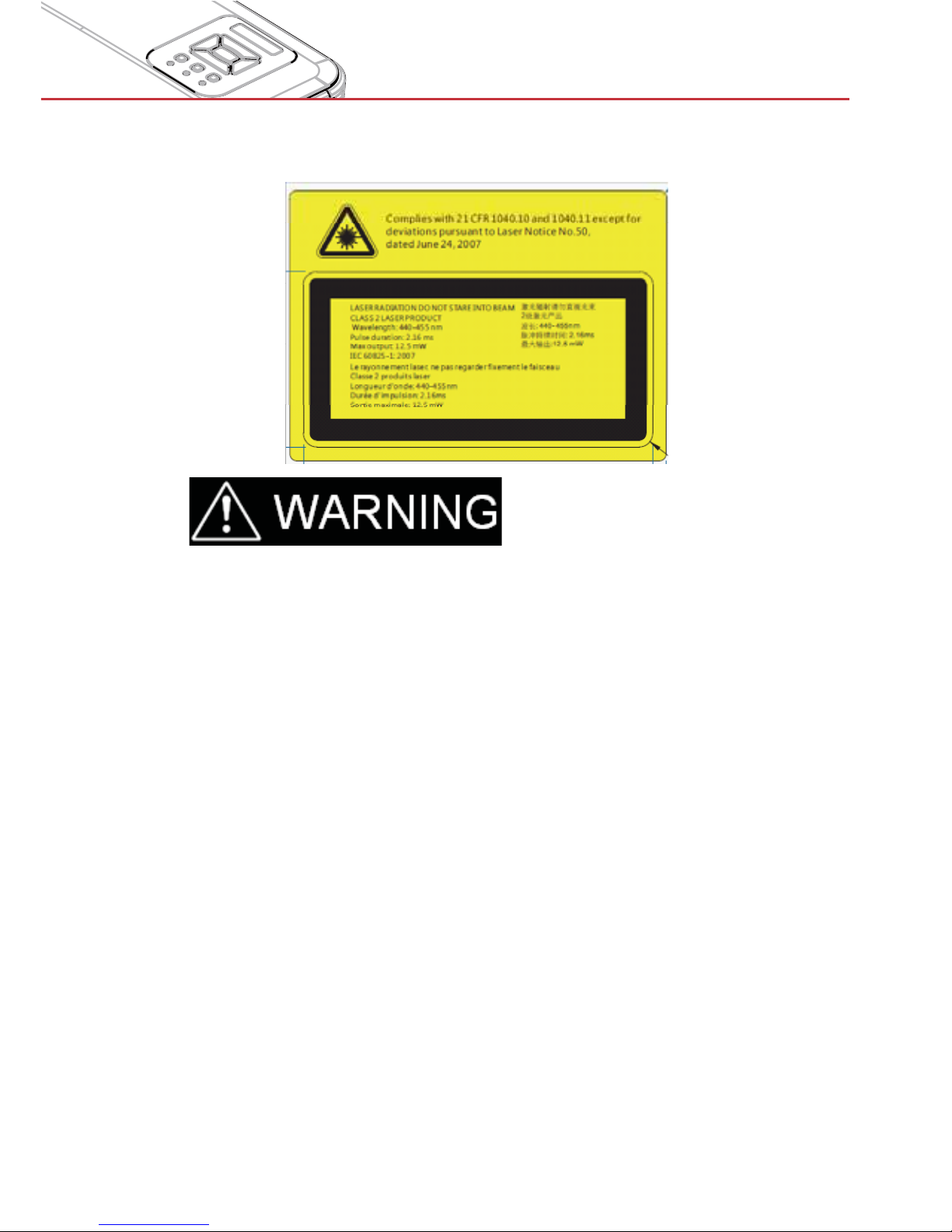
> This projector is a Class 2 laser device that conforms with IEC 60825-1:2007
and CFR 1040.10 and 1040.11.
> Class 2 laser product, Do Not Stare Into Beam.
> This projector has built-in Class 4 laser module. Disassembly or modification
is very dangerous and should never be attempted.
> Any operation or adjustment not specifically instructed by the user’s guide
creates the risk of hazardous laser radiation exposure.
> Do not open or disassemble the projector as this may cause damage by the
exposure of laser radiation.
> Do not stare into beam when the projector is on. The bright light may result in
permanent eye damage.
> Without following the control, adjustment or operation procedure may cause
damage by the exposure of laser radiation.
> Adequate instructions for assembly, operation, and maintenance, including
clear warnings concerning precautions to avoid possible exposure to laser
and collateral radiation in excess of the accessible emission limits in Class 2.
v.2.0 / 1512
 Loading...