

DNM Design 3-D Owners manual
3D Operating Notes Before switching on the 3D Pre-Amplifiercheck the following settings on
the power supply and the pre-amplifier.
The 3D Pre-Amplifier Power Supply.
Three types of power supply have been designed for the 3D Pre-Amplifer. They are
named 3D Primus, 3D Twin and 3D Six and they can also be indentified numerically
as 1, 2 and 6. The power supply complexity, the connection pattern in the preamplifier and accuracy of setup are factors that distinguish the three pre-amp models.
Check that the Power Supply is set tothe correct mains voltage. A rotary switch
sets the mains voltage between 120 volts or 220 volts and this can be found on the
back panel of the power supply within the group of controls located on the IEC mains
input panel. The selected voltage is set by turning the rotary switch with a
screwdriver. Also on this panel is the mains on-off switch and the mains fuse.
When the voltage is changed the mains fuse should also be changed to allow for the
difference in current drawn by the power supply at high and low mains voltages.
Fuse ratings are 1 amp medium blow at 220 volts and 2 amp medium blow at 120
volts. If the power supply is plugged into the higher voltage when set to accept the
lower one the mains fuse will blow.
Before switching on the power supply plug the flat ribbon cable/cables into the preamplifier's rear panel ten-way power supply sockets- taking note of the following
points.
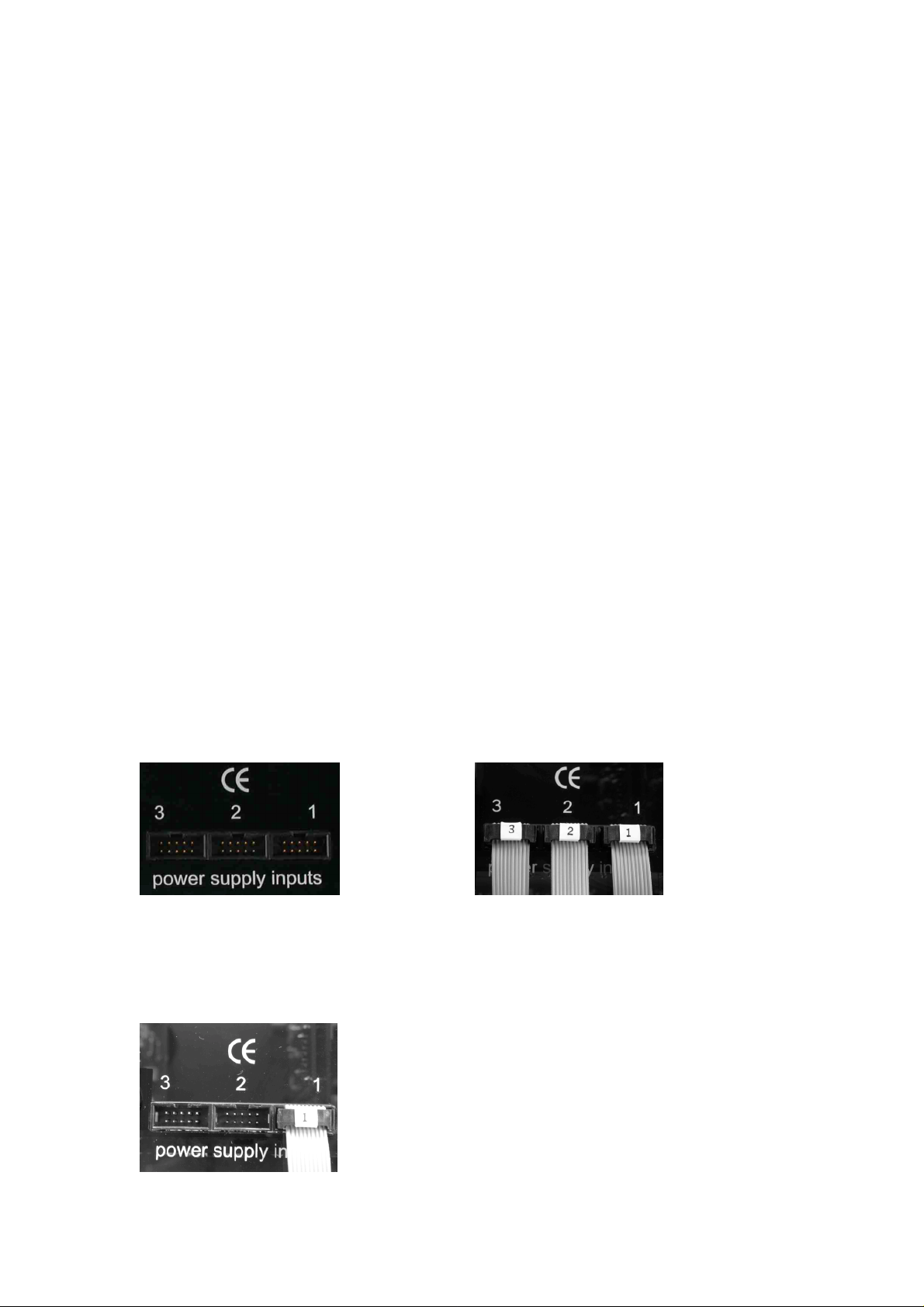
The pre-amplifier sockets are numbered 1, 2 and 3 and in the case of the Six power
supply and Six Pre-amplifier with the Six distribution board all three sockets are
connected to three ribbon cables. In this case it is important to ensure that the plugs on
the ribbon cables are number matched to the sockets on the pre-amplifier as shown
below to ensure correct performance.
In the case of the Twin and Primus supplies there is only one ribbon cable and this is
plugged into the number 1 input as shown below. If it is accidently plugged into one
of the other inputs sockets 2 or 3 no harm will be done but no power will reach the
pre-amplifier.
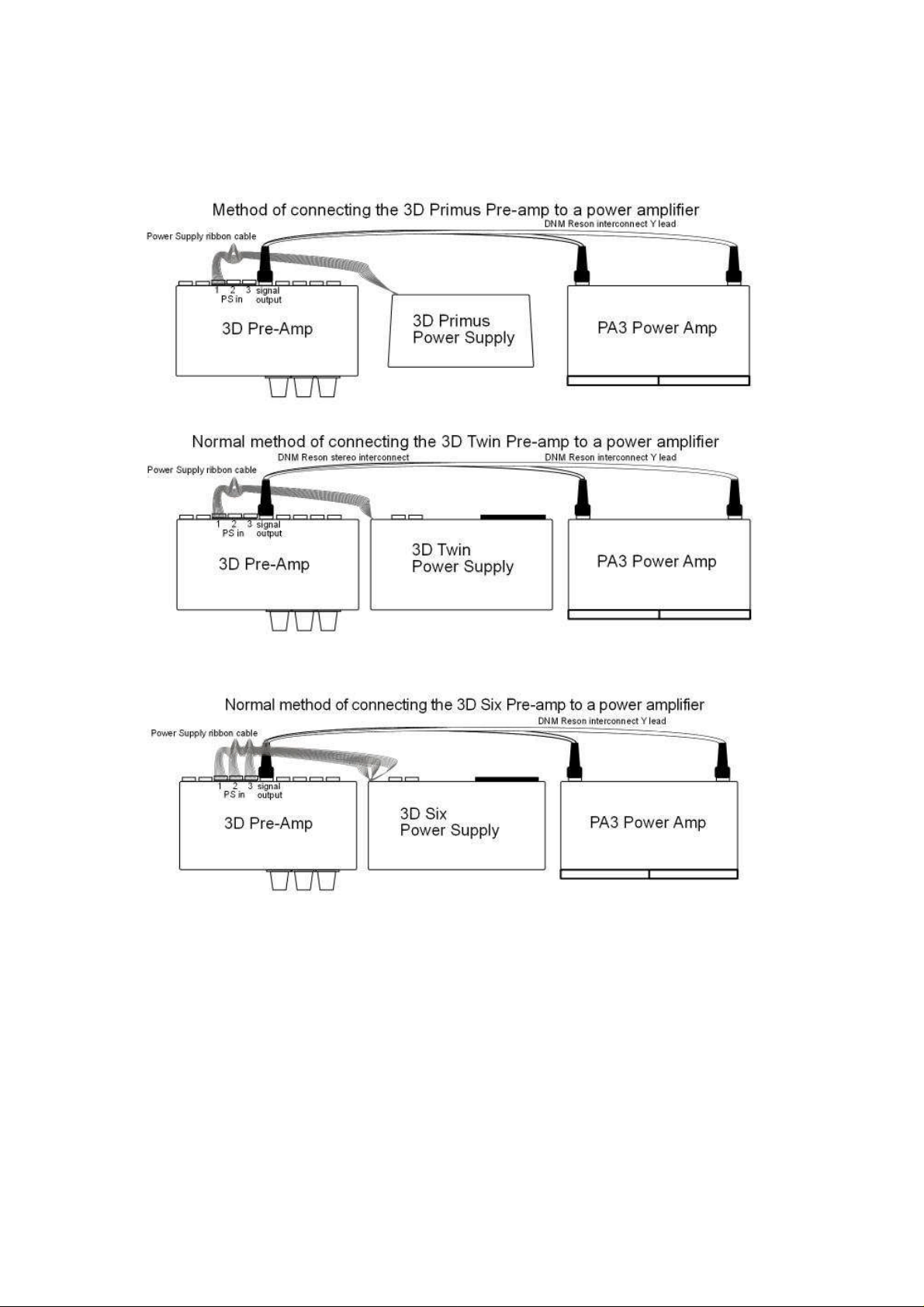
Connecting the 3D pre-amplifier to the power amplifier.
Normally the 3D Pre-Amplifier’s signal output socket should be connected to the
power amplifier directly as shown in the illustrations below.
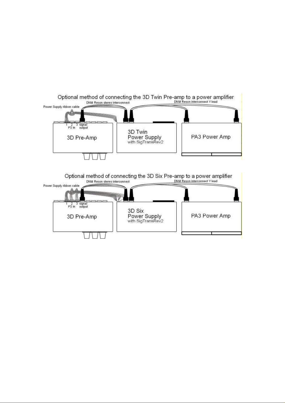
The 3D Twin or Six Pre-Amplifier output signal should normally be connected
directly to the power amplifier as shown on page 2. In a system setup where it is more
convenient to route the signal via the power supply extra Din sockets are provided on
the power supply for this purpose. The power supply must be fitted with“Signal
Transfer Board Rev2”(marked in copper on the signal transfer board underneath the
power supply motherboard).
This optional way of connecting may be preferred to obtain the shortest cable
arrangement or for convenience of equipment layout.
It will be necessary to use a shielded co-axial cable for the pre-amplifier to poweramplifier connection in situations where hum pickup may be likely, as in the case of a
valve power amplifier with a high input impedance. This cable can be supplied by
DNM Design.
 Loading...