

Page 1
12843 Foothill Blvd. Suite C
Sylmar, California 91342
V: 818.898.3380
F: 818.898.3360
sales@dnfcontrols.com
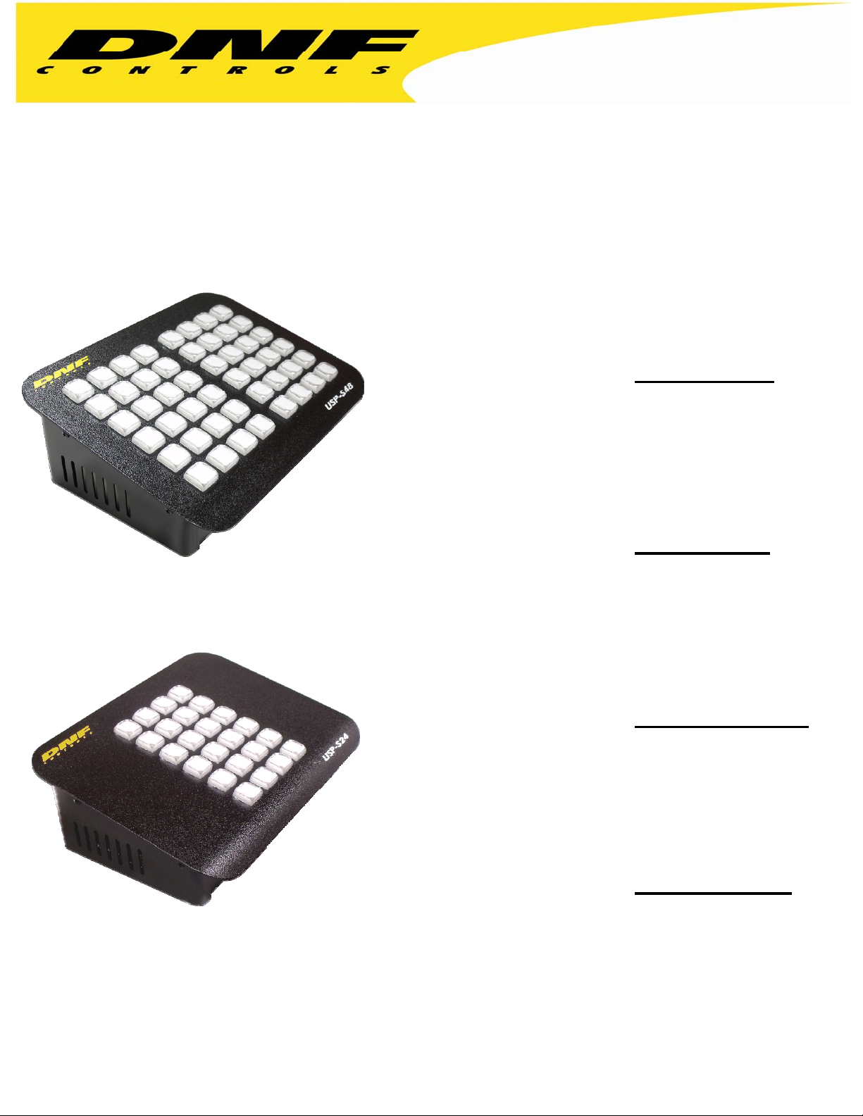
USP-S24 & USP-S48
Multi-purpose ― Web-browser Configurable
24 and 48 Pushbutton Switch Panels
USP-S24 and USP-S48 RELIABILITY
Ethernet connection to Windows® computers
Eliminates USB connectivity issues in mission critical
applications
Single button control for commonly used functions
Reduction in errors saves time and money
USP-S24 and USP-S48 FLEXIBILITY
SNMP – Ethernet – Serial control capability
Multi-function Pushbutton Panels for tally and command
Control and Tally multiple devices
Perfect for Production Studio and Control Room integration
Integrate into DNF FLEX Control Network®
USP-S24 and USP-S48 ASSIGNABILITY
Create the perfect panel for your unique application
No software programming or scripting– use standard web
browsers
Drop down menus and fill-in text boxes used to assign
Commands and Tallies to each pushbutton
USP-S24 and USP-S48 DESIRABILITY
Compact, desktop, tactile switch panels
Relegend-able Keycaps
Green/Amber/Red Tally indicators
Power Over Ethernet (POE) or External Power Supply
Page 1 of 27
Page 2

TABLE OF CONTENTS
1. INSTALLATION & CONFIGURATION............................................................ 3
2. GPI EVENTS Configuration Web Page......................................................... 5
3. GPO ACTIONS Configuration Web Page..................................................... 6
4. KEY MAPPER Configuration Web Page....................................................... 7
5. SERIAL PORT CONFIGURATION Web Page............................................... 8
6. SERIAL TRANSMIT ACTIONS Configuration Web Page ......................... 9
7. REMOTE DEVICE ASSIGNMENT Configuration Web Page.................. 10
8. ETHERNET TRANSMIT ACTIONS Configuration Web Page................. 12
9. SNMP TRANSMIT ACTIONS Configuration Web Page........................... 13
10. EVENT ACTION TABLE Configuration Web Page...................................14
11. TALLY ASSIGNMENT Configuration Web Page...................................... 17
12. USP-S24/48 TO GTP-32/DC20 SYSTEM CONFIGURATION...................19
13. PANEL KEY MAPPER™ APPLICATION..................................................... 20
14. REAR PANEL CONNECTORS....................................................................... 22
15. GPIs, WET/ DRY Configuration.................................................................... 24
16. GPOs, WET/ DRY Configuration................................................................. 25
17. BUILT-IN SELFTEST........................................................................................ 26
18. DNF CONTROLS LIMITED WARRANTY..................................................... 27
Revision History
Version 1.0 Original
Version 1.1 Added Self Test description
Version 1.2 Updated SNMP OID Value Type description
Version 1.3 Identified source port number (50000) used for UDP Ethernet
Transmit Actions
Version 1.4 Identify Ethernet connection as 10BASE-T Half Duplex
Page 2 of 27
Page 3

1. INSTALLATION & CONFIGURATION
INSTALLATION
Refer to the REAR PANEL CONNECTOR
information.
Refer to the GPIs, WET/ DRY Configuration
GPI and GPO Wet/ Dry configuration information.
Use the GPI Events
Use the GPO Actions
Use the Serial Port Configuration
Use the Remote Device Assignment
Use the Event Action Table
Use the Tally Assignment
POWER
The USP-24/48 is powered from an Ethernet switcher/ router that supports Power Over Ethernet
(POE), or from the supplied external power supply. Power requirement is 12 volts DC at 2 amps
from an external power supply and 13 Watts from POE switch.
DEFAULT ETHERNET CONFIGURATION (Supports only 10BASE-T at Half-Duplex)
IP Address: 192.168.10.217
Subnet Mask: 255.255.255.0
Gateway: 192.168.10.1
RESET
web page to configure GPI operation.
web page to configure GPO operation.
web page to configure the serial port.
web page to map key presses to Remote Devices and the serial port.
web page to configure key tallies.
S section for GPI, GPO, and serial connector pin out
and GPOs, WET/ DRY Configuration sections for
web page to configure Ethernet connections.
Press the RESET switch on the rear of the unit to reboot it.
Switch S1
Press and hold the S1 switch for 10 seconds to reset the IP address, subnet mask, Gateway, and
configuration to factory defaults.
CONFIGURATION
The USP-S24/48 is configured using a standard web browser (Internet Explorer, Firefox, and
Chrome). Enter the USP’s IP address in the Address/ URL bar, typically located at the top of the
web browser page, to access the configuration Home Page. Use the links on the left side of the
Home Page to access the desired configuration web page.
All configuration settings are saved in non-volatile memory in the unit. Settings are retained
when power is removed.
Settings may be uploaded to a computer as a configuration file (.dnf) for storage. Configuration
files may be downloaded from a computer into the USP to restore a saved configuration. A
configuration file contains all of configuration settings except IP address, subnet mask, and
gateway address. Partial configuration upload or download is not supported. The configuration
file is a not a text formatted file. It can not be viewed or modified with a text editor.
To access the System Configuration web page, use the following log-on when prompted.
User name: dnfuser
Password: controls
Page 3 of 27
Page 4
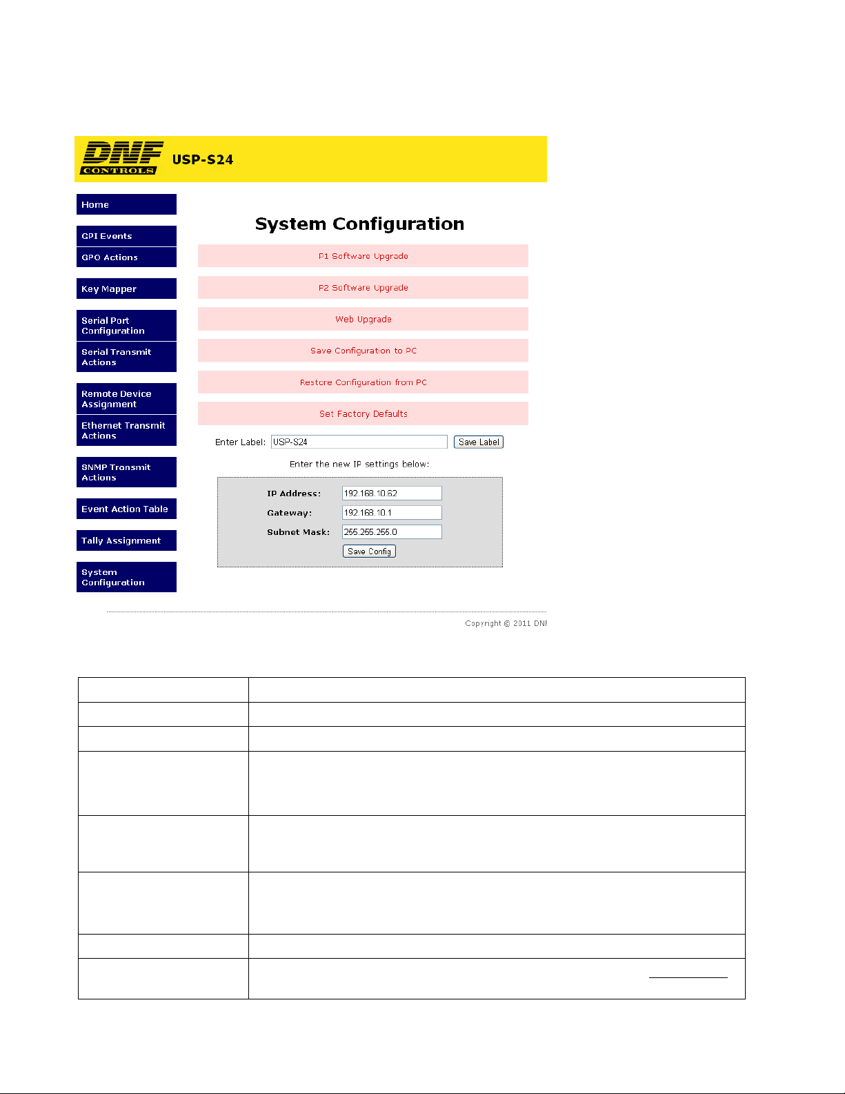
SYSTEM CONFIGURATION Web Page
P1 Software Upgrade: Use this link to install the P1 upgrade file provided by DNF Controls
P2 Software Upgrade: Use this link to install the P2 upgrade file provided by DNF Controls
Web Upgrade: Use this link to install the Web pages upgrade file provided by DNF Controls
Save Configuration to PC: Use this link to save the current configuration to a configuration file on a
computer. The web browser will prompt for file name and directory. The file
extension must be ‘dnf’.
Restore Configuration
from PC:
Set Factory Defaults: Use this link to reset all configurations to factory defaults. This will NOT change
Enter Label Enter device identifier that is displayed on the home page.
Enter the new IP settings
below:
Use this link to download a configuration file from your computer. The web
browser will prompt for directory and configuration file name. The file extension
must be ‘dnf’.
the IP address, subnet mask or gateway address. The unit will automatically
reboot.
Enter the new IP address, Gateway, and Subnet Mask. Click on Save Config to
save the new entries. The AIB will automatically reboot.
Page 4 of 27
Page 5
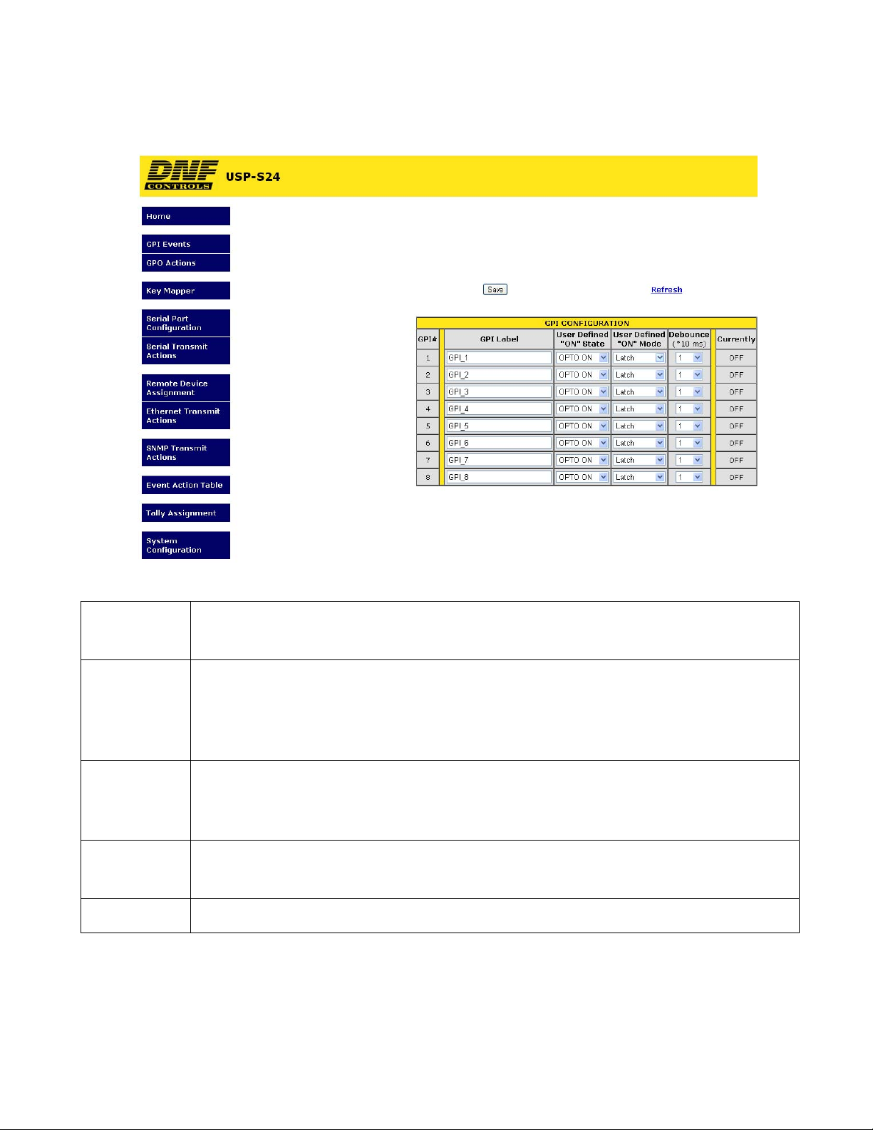
2. GPI EVENTS Configuration Web Page
GPI Label Enter any 15 characters or symbols. For convenience only.
Used in Event Action Table
User Defined
ON State
User Defined
ON Mode
Debounce Time The time period that the GPI must remain ON to be detected as ON.
Currently Current state of GPI as defined by User Defined ON State.
OPTO ON: The GPI is ON when the opto-isolator is energized (powered).
The GPI is OFF when the opto-isolator is de-energized.
OPTO OFF: The GPI is ON when the opto-isolator is de-energized.
The GPI is OFF when the opto-isolator is energized (powered).
LATCHED: The GPI turns ON and stays ON. The GPI turns OFF and stays OFF.
MOMENTARY: The GPI turns ON for a short time and then turns OFF and stays OFF.
This pattern repeats every time the GPI become active.
The selected time is multiplied by 10 milliseconds to compute the actual Debounce time.
Page 5 of 27
Page 6
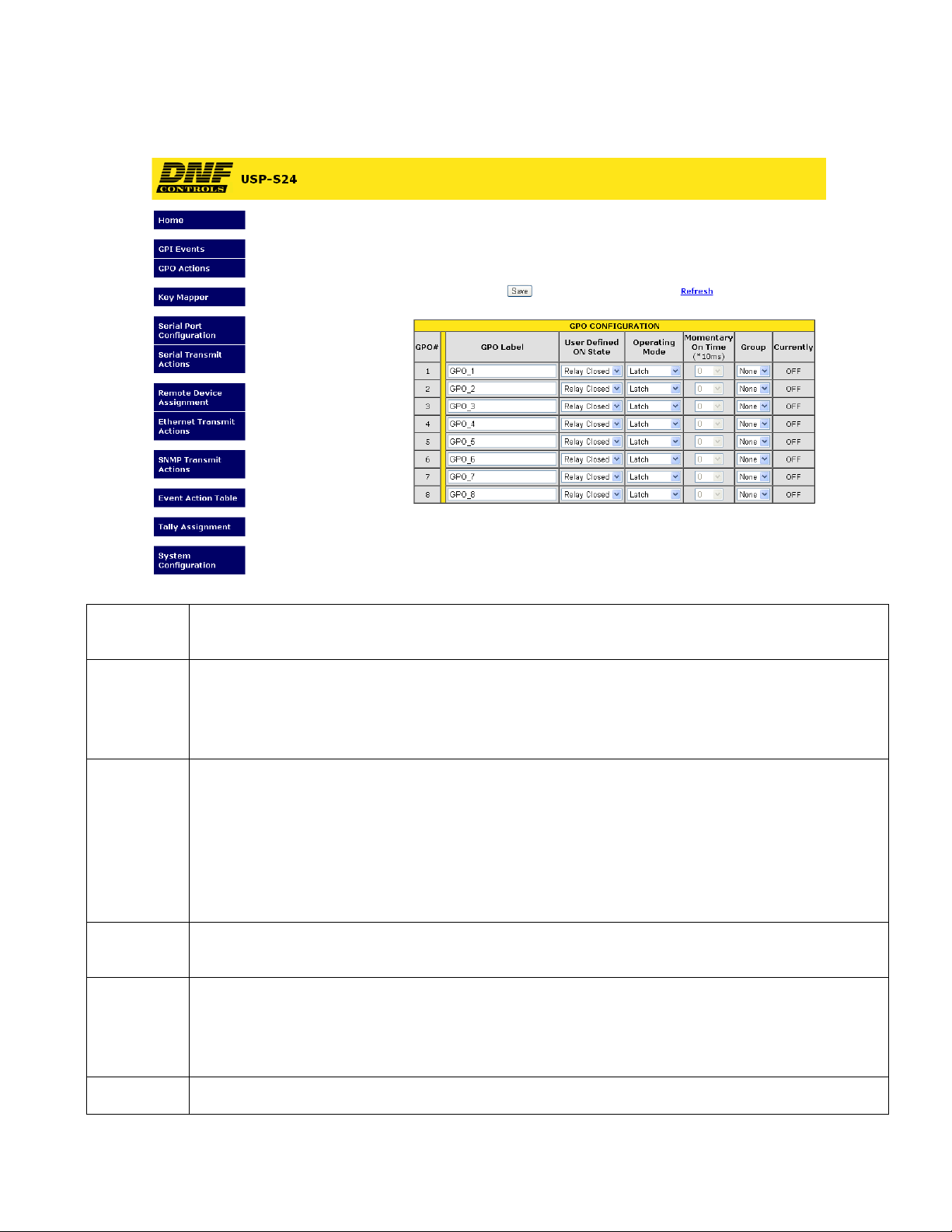
3. GPO ACTIONS Conf iguration Web Page
GPO Label Enter any 15 characters or symbols. For convenience only.
Used in Event Action Table
User Defined
ON State
User Defined
Operating
Mode
Momentary
ON Time
Group Radio Group RG1 – RG4: Only one GPO in a Group can be ON at a time. Before a GPO is
RELAY OPEN: The relay is OPEN when the GPO is ON.
The relay is CLOSED when the GPO is OFF.
RELAY CLOSED: The relay is CLOSED when the GPO is ON.
The relay is OPEN when the GPO is OFF (Factory Default).
MOMENTARY: The GPO turns ON, waits for the MOMENTARY ON TIME to expire, and then
automatically turns OFF.
LATCH: The GPO turns ON and stays ON.
The GPO turns OFF and stays OFF.
TOGGLE: The GPO alternates states with each GPO ON action.
The GPO turns ON if it was previously OFF.
The GPO turns OFF if it was previously ON.
For MOMENTARY operating mode only. ON duration for Momentary GPO. Drop down menu
settable from 0.01 sec to 2.0 sec.
turned ON, all of the other GPOs in the group are immediately turned off. (Break before make)
FLIP-FLOP FF1–FF4: Only two GPOs can be assigned to one Flip-Flop group. Like a GPO
Radio Group, when one GPO turns ON the other automatically turns OFF.
Currently Current state of GPO as defined by User Defined ON State.
Page 6 of 27
Page 7
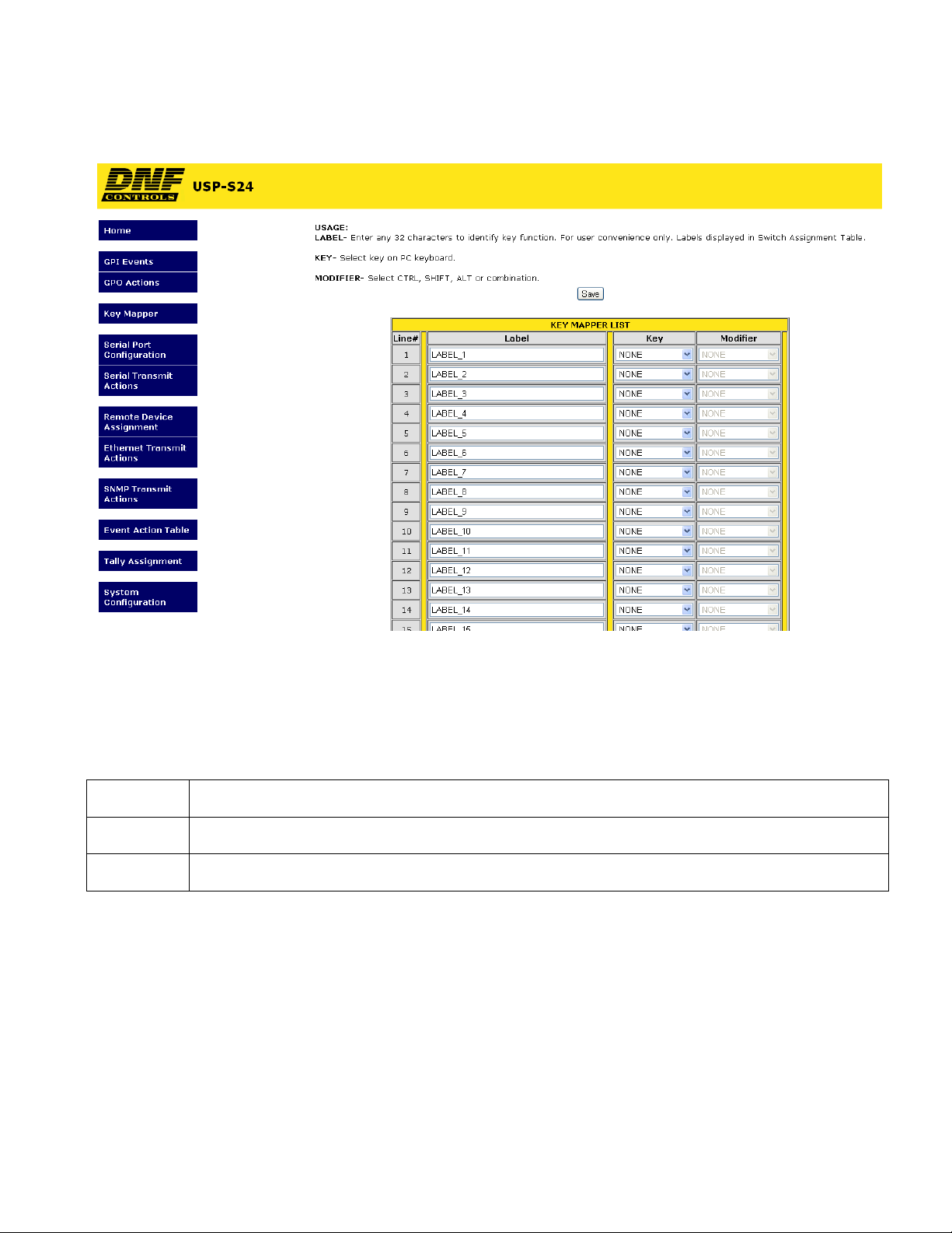
4. KEY MAPPER Configuration Web Page
The Key Mapper List contains 48 entries. Select a PC keyboard combination from the
drop down menus and assign an identifier label for the Event Action Table.
When a USP key is pressed, the assigned Key Mapper List entry is transmitted to the
Panel Key Mapper application, pkm.exe, running on the Microsoft Windows based
remote device.
Label Enter any 32 characters or symbols. For convenience only. Used in Event Action Table
Key Select PC Keyboard key from drop down menu
Modifier Select NONE or CTRL, SHIFT, ALT combination
Page 7 of 27
Page 8
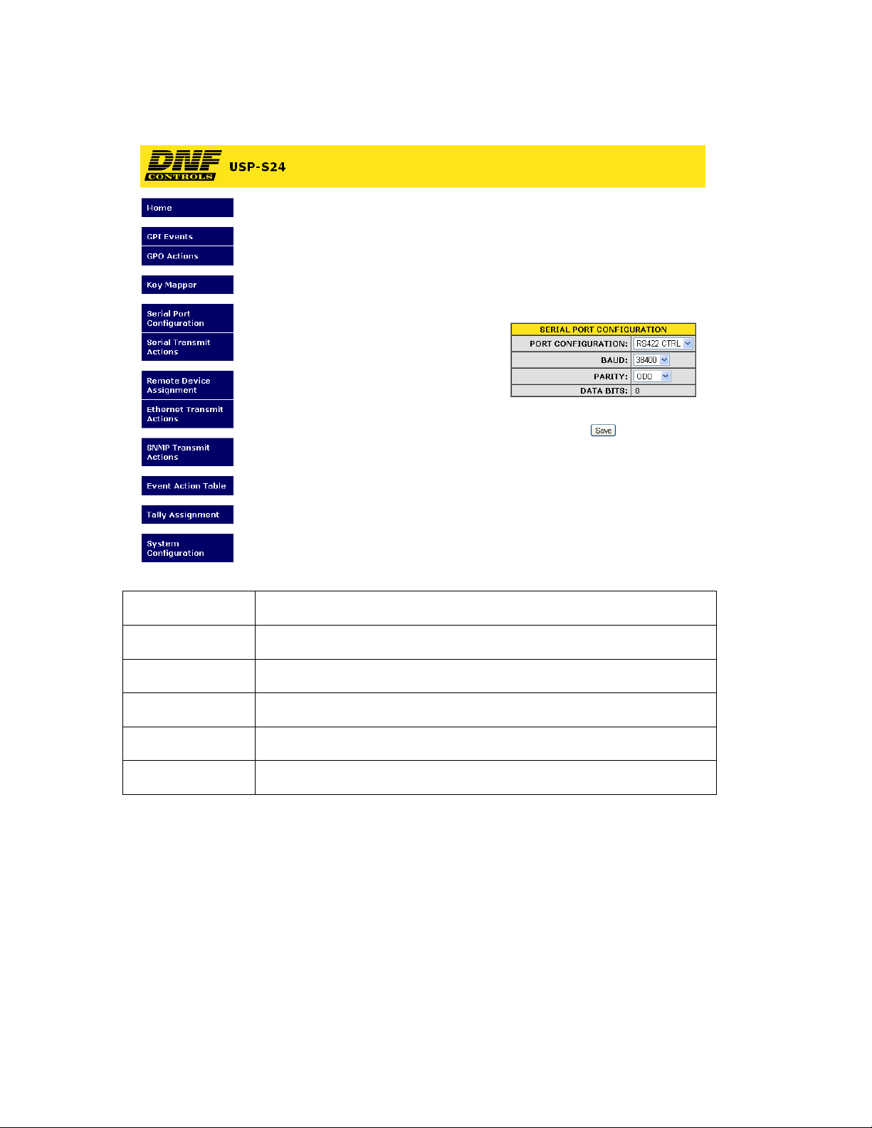
5. SERIAL PORT CONFIGURATION Web Page
Port Configuration RS232 DTE, RS422 Controller, or RS422 Device
Baud Rate 300, 1200, 2400, 4800, 9600,19200, 38400
Parity None, Odd, Even
Data Bits Fixed at 8
Stop Bits Fixed at 1
Start Bits Fixed at 1
Page 8 of 27
Page 9
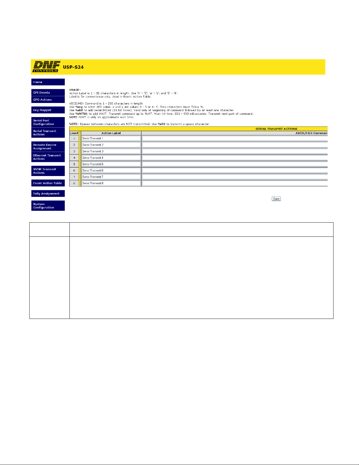
6. SERIAL TRANSMIT ACTIONS Confi guration Web Page
Action Label Enter any 32 characters. This label is for convenience only and is used in the Event Action Table.
ASCII/ HEX
Command
The ASCII/HEX Command is 1 - 256 characters in length.
Use %yz to enter a HEX value. ‘y’ and ‘z’ are values 0 - 9 or A- F. Two characters must follow %.
Use %BR to add a serial BREAK (18 bit times). BREAK is valid only at the beginning of a
command and must be followed by at least one character.
Use %WTttt to add a WAIT time, 001 - 999 milliseconds. Three numbers must follow %WT. The
characters preceding %WT are sent immediately. The characters after %WTttt are sent after the
wait time expires. More than one %WT can be included in a command. NOTE- %WT is only an
approximate wait time.
NOTE- Spaces between characters are NOT transmitted. Use %20 to transmit a space character.
Page 9 of 27
Page 10
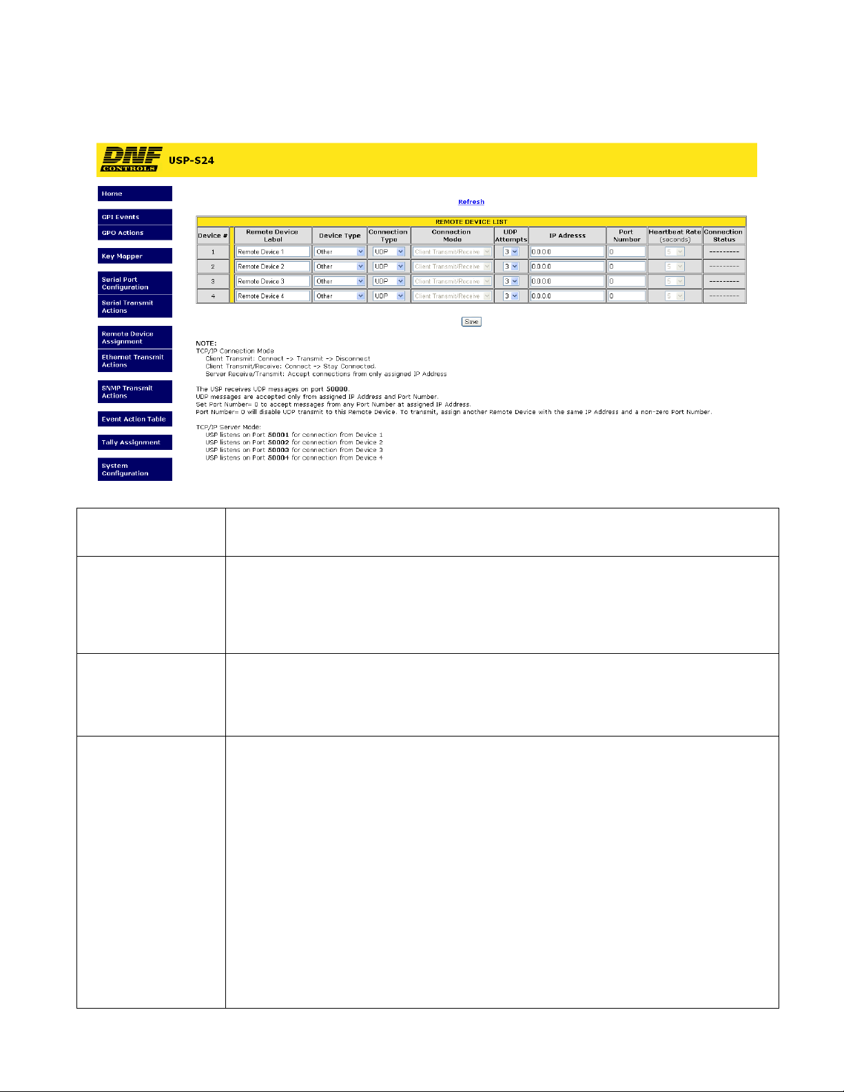
7. REMOTE DEVICE ASSIGNMENT Configuration Web Page
Remote Device Label Enter any 32 characters. This label is for convenience only and is used in the Event
Action Table.
Device Type OTHER
PKM- Use to connect to DNF’s Panel Key Mapper application running on a Microsoft
Windows computer.
GTP-32/DC20- Use to connect to DNF Controls GTP-32 and DC20 devices
Connection Type Select UDP, SNMP, or TCP/IP.
NOTE- USP-S24/48 listens only on Port 50000 for UDP messages.
For UDP Ethernet Transmit Actions, the USP-S uses source port 50000
Connection Mode For TCP/IP Only
Client Transmit: Establish connection to remote device.
Transmit command.
Disconnect from remote device.
Client Transmit/Receive: Establish connection to remote device.
Maintain connection to remote device.
Server Receive/Transmit: Accept connection from client.
Only client at assigned IP Address can connect
The client is responsible for maintaining connection.
Server Mode only, AnyWhere Interface Box listens on the following ports:
Port 50001 for connection from Remote Device 1
Port 50002 for connection from Remote Device 2
Port 50003 for connection from Remote Device 3
Port 50004 for connection from Remote Device 4
Page 10 of 27
Page 11

UDP Attempts For UDP and SNMP Connection Type only.
The number of times that the message will be sent separated by 10milliseconds. Since
UDP does not provide guaranteed delivery, UDP Attempts provides more than one
transmit attempt to deliver the message.
IP Address Client or Destination IP address
Port Number Destination port number for transmit actions
Source port number for receive events
Heartbeat Rate For GTP-32/DC20 Device Types. Default value is 5 seconds. Communication error is
defined as loss of two consecutive heartbeats.
Connection Status For GTP-32/DC20 Device Type and TCP/IP Connection Type only.
Please note-
The USP-S24/48 will transmit messages only to the specified IP address and Port number listed in
the Remote Device Assignment Table.
The USP-S24/48 will only accept UDP and TCP/IP messages only from the specified IP address
and
Port number listed in the Remote Device Assignment Table. The sender’s IP address and Port
number must match the entry in the table.
Page 11 of 27
Page 12

8. ETHERNET TRANSMIT ACTIONS Configuration Web Page
Action Label Enter any 32 characters. This label is for convenience only and is used in the Event Action
Table.
ASCII/ HEX
Command
NOTE
The ASCII/HEX Command is 1 - 256 characters in length.
Use %yz to enter a HEX value. ‘y’ and ‘z’ are values 0 - 9 or A- F. Two characters must
follow %.
Use %WTttt to add a WAIT time, 001 - 999 milliseconds. Three numbers must follow %WT.
The characters preceding %WT are sent immediately. The characters after %WTttt are sent
after the wait time expires. More than one %WT can be included in a command. NOTE- %WT
is only an approximate wait time.
NOTE- Spaces between characters are NOT transmitted. Use %20 to transmit a space
character.
- For UDP Ethernet Transmit Actions, the USP-S uses source port 50000
Page 12 of 27
Page 13

9. SNMP TRANSMI T ACTIONS Configuration Web Page
Action Label Enter any 32 characters. This label is for convenience only and is used in the Event Action
Table.
Community Community string is 1 - 32 characters in length. Typical value is 'public'.
Command SET, GET, GET RESPONSE
Object
Identifier
(OID)
Value Type
OID Value
The OID is 8 - 256 decimal values in length entered in dot notation. Only decimal values are
accepted. ie: 1.22.333.4.55.666.7.88. Maximum entered decimal value is 99999999.
OID Value Type:
Integer: Enter decimal value 0 – 999999 for OID value
Octet Integer: Enter decimal value 0 – 999999 for OID value
Octet String: Enter 16 alphanumeric characters
NULL: Set to NULL when no OID value is entered.
Page 13 of 27
Page 14

10. EVENT ACTION TABLE Configuration Web Page
On an Event Action Table line, select an EVENT IN on the left side of the table and then
select an ACTION on the right side. Some events only support ON ACTIONS, so the
OFF ACTION entries will be grayed out. There are 64 lines in the Event Action Table.
One EVENT IN can trigger more than one ACTION. Select the same EVENT IN on
multiple lines and then select an ON or OFF ACTION on each line.
Only EVENTs and ACTIONs associated with the Remote Device’s Device Type or
Connection Type will be displayed in the drop down menus. If the desired event or
action is not displayed, then go to the Remote Device Assignment web page and change
the Device Type or Connection Type for the Remote Device.
In the Event Action and Tally Assignment Tables, the USP-S24/48 keys are identified by
their Column, Row position for easy identification. Key number #11 is located in column
#1, on row #1. Key number #16 is located in column #1, on row #6. Key number #84 is
located in column #8, on row #4.
Page 14 of 27
Page 15

E
V
E
N
T
I
N
Source
Event
Type
None (Disable line)
Local Event
Local: GPI GPI changed from OFF to ON. The selected ON ACTION will execute.
GPI changed from ON to OFF. The selected OFF ACTION will execute
Key Press ( Only available for Device Type “PKM”)
USP-S24/48 key press (ON ACTION) or key release (OFF ACTION).
Remote:
GTP-32/DC20 Receive ( Only available for Device Type “GTP-32/DC20”)
Use Tally Assignment web page to map received Event Label to key tally
O
N
A
C
T
I
O
N
Event
Local /
Remote
Type
GPI Number or Key Number
Execute Action on Local resource
Execute Action on Remote Device
Local: GPO Do Nothing
Turn GPO ON
Turn GPO OFF
Serial Transmit Action
Transmit selected Serial Action command once. If command contains
WAIT (%WT), then transmit all characters prior to %WT, wait for the time
period defined by %WT, and then transmit the remaining characters or
until the next %WT. A command may contain more than one %WT.
Remote:
Ethernet Transmit Action
Transmit the selected Ethernet Action command. If command contains
WAIT (%WT), then transmit all characters prior to %WT, wait for the time
period defined by %WT, and then transmit the remaining characters or
until the next %WT. A command may contain more than one %WT.
SNMP Transmit Action (Only available for Connection Type “SNMP”)
Transmit the selected SNMP Action. WAIT is not supported. The SNMP
Action entry must contain a “Community” entry and OID entry.
Action
Label
GTP-32/ DC20 (Only available for Device Type “GTP-32/DC20”)
Transmit Key Press or Key Release message using Event In Key number.
GPO Number
Serial Transmit Action
Ethernet Transmit Action
SNMP Transmit Action (Only available for Remote Device Connection Type “SNMP”)
Page 15 of 27
Page 16

O
F
F
A
C
T
I
O
N
Local /
Remote
Type
Execute Action on Local resource
Execute Action on Remote Device
Local: GPO Do Nothing
Turn GPO ON
Turn GPO OFF
Serial Transmit Action
Transmit selected Serial Action command once. If command contains
WAIT (%WT), then transmit all characters prior to %WT, wait for the time
period defined by %WT, and then transmit the remaining characters or
until the next %WT. A command may contain more than one %WT.
Remote:
Ethernet Transmit Action
Transmit the selected Ethernet Action command. If command contains
WAIT (%WT), then transmit all characters prior to %WT, wait for the time
period defined by %WT, and then transmit the remaining characters or
until the next %WT. A command may contain more than one %WT.
SNMP Transmit Action (Only available for Connection Type “SNMP”)
Transmit the selected SNMP Action. WAIT is not supported. The SNMP
Action entry must contain a “Community” entry and OID entry.
GTP-32/ DC20 (Only available for Device Type “GTP-32/DC20”)
Transmit Key Press or Key Release message using Event In Key number.
Action
Label
GPO Number
Serial Transmit Action
Ethernet Transmit Action
SNMP Transmit Action (Only available for Remote Device Connection Type “SNMP”)
Page 16 of 27
Page 17

11. TALLY ASSIGNMENT Configuration Web Page
Use the Tally Assignment Table to assign a tally to a key. The Tally Assignment Table
contains one entry for each key. A key can tally OFF and ON, or up to 4 states (OFF,
ET1, ET2, ET3).
Key Number The USP-S24/48 keys are identified by their Column, Row position for easy
identification. Key number #11 is located in column #1, on row #1. Key number #16 is
located in column #1, on row #6. Key number #84 is located in column #8, on row #4.
Key Label Enter any 32 characters. This label is for convenience only and is used only on this
web page.
Tally Type Local- Tally local GPI, GPO, or key press
Remote- Tally status from Remote Device (GTP-32/DC20 Device Type)
Tally Source
Local Follow Key- Tally is ON when key is pressed
Tally is OFF when key is released
Follow GPI- Tally is ON when GPI is ON
Tally is OFF when GPI is OFF
Follow GPO- Tally is ON when GPO is ON
Tally is OFF when GPO is OFF
Remote Follow GTP/DC- Assign one Event Label
Tally is ON when assigned Event Label is ON
Tally is OFF when assigned Event Label is OFF
Extended Follow GTP/DC- Assign up to 4 Event Labels
Tally is ON when any of the assigned Event Labels is ON
The associated Event Label’s color entry is used
Tally is OFF when all assigned Event Labels are OFF
Page 17 of 27
Page 18

Tally Tally Identifiers: OFF, ON or ET1, ET2, ET3, ET4 (Read Only Labels)
Tally Color Dark
Red
Green
Amber
Flashing Red
Blinking Red
Flashing Green
Blinking Green
Flashing Amber
Blinking Amber
GPI/O
Number
Event Label Manually enter, or cut & paste, the Event Label from the GTP-32’s or DC20’s Event
GPI: 1 – 8
GPO: 1 – 8
Notification Table. The event label is case sensitive, may not contain spaces, and must
exactly match the Event Notification Table entry. (Refer to the GTP-32 or DC20 User
Manual.)
Page 18 of 27
Page 19

12. USP-S24/48 TO GTP-32/DC20 SYSTEM CONFIGURATION
Define Remote Devices that the
USP will communicate with.
Identify Remote Device
to send data to and
receive data from
GTP-32 or DC20
Event Action Table
Map Key Press and Key Release
to a Remote Device. Map key
press/release to one or more
Remote Devices
Tally Asignment Table
USP Event Definitions
Key presses to
Remote Device
Map USP Key Press/ Release to
a unique Source Event Label that
will be used in the GTP-32's
configuration tables.
USP Event Notifications
Status from
Remote Device
Map Tally Source to each Key.
Map local source or status from
Remote Device.
Send GTP-32 Events to one or
more USPs: GPI, GPO,
Combinatorial Event, UserRegister,
and more
Page 19 of 27
Page 20

13. PANEL KEY MAPPER™ APPLICATION
The DNF Controls supplied Panel Key Mapper™ is a small Windows® application that
maps USP-S24 and USP-S48 key presses to HOTKEYs for Editors, Graphic devices,
Production Playout & Automation systems, as well as other Windows based applications.
For example, map USP-S24 Key: #2 to “SHIFT F3”
#10 to “CTRL SHIFT F10”
#23 to “CTRL ALT F1”
The USP-S24/48 connects to the Windows computer running Panel Key Mapper
(pkm.exe) over an Ethernet connection, eliminating USB connectivity issues in mission
critical applications.
The USP-S24/48 provides single button control for commonly used functions reducing
errors, which saves time and money.
Use the Key Mapper web page to create the HOTKEY key combinations used by the
Editor or other Windows applicaton. Use the Event Action Table to map a key press to
one or more Key Mapper entries and assign the Remote Device to transmit the HOTKEY
to. One HOTKEY can be sent to multiple remote devices.
INSTALLATION
Install the supplied pkm.exe and pkm.ini files in a folder on the Windows computer.
Edit the pkm.ini with Notepad.exe or other simple text editor. (Do not use a word
processor.) Change the Panel 1 IP address to the IP address of the USP-S24 or USPS48 that will send HOTKEYs to the computer. Change the Port number from 50000 to
any other port number if that port is already in use on the computer.
Add pkm.exe to the computer’s Start Up folder or create a Scheduled Task to launch the
application when the computer starts up. Or, using a mouse, double click on the
application to launch it. A black box will appear briefly on the screen and then disappear.
Check Windows’ Task Manager to confirm that pkm.exe is running.
LOGGING
pkm.exe will create a log file, pkm.log, in the same folder that it resides. Open the log
file with a text editor. Each time pkm.exe is launched the log file will show:
04/02/2011, 13:09:41 DNF Control Panel Key Mapper Log
04/02/2011, 13:09:41 pkm.exe startup
04/02/2011, 13:09:41 Console hidden
04/02/2011, 13:09:41 C:\temp\pkm.exe Version 1.3
04/02/2011, 13:09:41 Successfully opened file C:\temp\pkm.ini
04/02/2011, 13:09:41 Successfully processed file C:\temp\pkm.ini
04/02/2011, 13:09:41 Listening on Port 50000 for Panel Key Mapper commands
04/02/2011, 13:09:41 Accepting commands from Panel IP Address 192.168.10.62
where Panel IP Address and Port will reflect the pkm.ini entries.
Every command received from the USP-S24/48 will be logged as follows:
04/01/2011, 23:50:05 Received OID Value: KM_70:1
Page 20 of 27
Page 21

04/01/2011, 23:50:05 Generate Key Press/Release sequence VKEY= 70, SCAN= 3b,
SHIFT= 0, CTRL= 0, ALT= 0
04/01/2011, 23:50:05 Received OID Value: KM_74_C_A:1
04/01/2011, 23:50:05 Generate Key Press/Release sequence VKEY= 74, SCAN= 3f,
SHIFT= 0, CTRL= 1, ALT= 1
04/01/2011, 23:50:05 Received OID Value: KM_37_C:1
04/01/2011, 23:50:05 Generate Key Press/Release sequence VKEY= 37, SCAN= 08,
SHIFT= 0, CTRL= 1, ALT= 0
04/01/2011, 23:50:05 Received OID Value: KM_33_A:1
Use Windows’ Task Manager to stop pkm.exe.
Page 21 of 27
Page 22

14. REAR PANEL CONNECTORS
Physical size: 8.25” W x 4.125” D x 1.5” H
GPI CONNECTOR
8 Isolated Opto-Isolator Inputs
Pin # Description Pin # Description
1 Ground 14
2 GPI 8 ─ 15 +V
3 +V 16 GPI 7 ─
4
GPI 7
+
5 GPI 6 ─ 18 +V
6 +V 19 GPI 5 ─
7
GPI 5
+
8 GPI 4 ─ 21 +V
9 +V 22 GPI 3 ─
10
GPI 3
+
11 GPI 2 ─ 24 +V
12 +V 25 GPI 1 ─
13
GPI 1
+
GPI 8
17
GPI 6 +
20
GPI 4 +
23
GPI 2 +
+
GPO CONNECTOR
8 Isolated Relay Contact Closure Outputs
Pin # Description Pin # Description
1 Ground 14 GP0 8 N.O
2 GPO 8 Com 15 Common Bus
3 +V 16 GPO 7 N.O.
4 GPO 7 Com 17 GPO 6 N.O.
5 GPO 6 Com 18 Common Bus
6 Common Bus 19 GPO 5 N.O.
7 GPO 5 Com 20 GPO 4 N.O.
8 GPO 4 Com 21 Common Bus
9 Common Bus 22 GPIO 3 N.O.
10 GPO 3 Com 23 GPO 2 N.O.
11 GPO 2 Com 24 Common Bus
12 Common Bus 25 GPO 1 N.O.
13 GPO 1 Com
Page 22 of 27
Page 23

REAR PANEL CONNECTORS (continued)
ETHERNET CONNECTOR
1- 10BASE-T Half Duplex
Supports Power Over Ethernet
USB CONNECTOR
Not Used
Press and hold 10 seconds to reset:
IP address to 192.168.10.217
Configuration to default
POWER CONNECTOR
12V DC, 2.0Amps
S1 Switch
SERIAL CONNECTOR
Pin
RS232 DTE RS422 Con tr oller RS422 Device
1
N/C
2
RxD Receive A (-) Transmit A (-)
3
TxD Transmit B (+) Receive B (+)
4
Tied to 6 Receive Common Receive Common
5
Ground N/C N/C
6
Tied to 4 Transmit Common
7
N/C Receive B (+) Transmit B (+)
8
N/C Transmit A (-) Receive A (-)
9
N/C Frame Ground Frame Ground
Frame Ground Frame Ground
Transmit Common
Page 23 of 27
Page 24

15. GPIs, WET/ DRY Configuration
EXAMPLE #1- Device Powered GPIs
GPI Connector
Ground
1
12
13
+5V
DEVICE #1
GPO #1
25
Internal +5VDC
GPI #1 (+)
GPI #1 (-)
24
23
+12V
GPI #2 (+)
GPI #2 (-)
11
EXAMPLE #2- WET GPIs using internal +5V
GPI Connector
DEVICE #2
GPO #1
1
GPO
provides
path to
ground
GPO
provides
path to
ground
GPI CONNECTION DIAGRAM
GPI Technical Data
330 Ohms
RInternal
Specification for GPI input:
1. Voltage: (Internal resistor only)
+3.3V minimum
+5V typical
+6V maximum
2. Current: (Internal resistor only)
5mA minimum
10mA typical
15mA maximum
RExternal
Power
External
Device
Ground
12
Wire
13
25
Internal +5VDC
Jumper
GPI #1 (+)
GPI #1 (-)
DEVICE #3
Ground
For typical 10mA current, if external voltage is
higher than +5V, a series resistor is required:
R
ext = (Vext - 4.5) / 0.01
V
ext = +9V => Rext = 450 Ohms
V
ext = +12V => Rext = 750 Ohms
V
ext = +24V => Rext = 1950 Ohms
24
23
11
Wire
Jumper
GPI #2 (+)
GPI #2 (-)
GPO #1
GPO
provides
path to
ground
GPO #2
Page 24 of 27
Page 25

16. GPOs, WET/ DRY Configuration
Page 25 of 27
Page 26

17. BUILT-IN SELFTEST
KEYBOARD SUB-SYSTEM Self Test
Tests keyboard switches and key indicators
To enter Keyboard Selftest:
On USP-S24, press and hold keys #11, #41, and #16.
On USP-S48, press and hold keys #11, #81, and #16.
All key indicators will go dark.
Press a key. The key indicator will turn GREEN.
Press key again. The key indicator will turn RED.
Press key again. The key indicator will turn AMBER.
Press key again. The key indicator will turn dark.
Reboot to exit Self Test.
SYSTEM Self Test
Tests switches, key indicators, GPIs, GPOs, Serial Transmit and Serial Receive
NOTE- Prior to entering Self Test mode, confirm that serial port has been configured for
RS232, 38400 baud and ODD parity. Web pages are not available when Self Test is
running.
Prior to powering up the unit, press and hold S1, located on the rear of the panel. All
keys will flash AMBER.
Release S1. (If S1 is held pressed for 10 seconds, all configuration items including IP
address will be set to factory defaults.)
All key indicators will turn GREEN.
Press key. Its indicator will turn RED.
Release key. Its indicator will turn GREEN.
Activate GPI #1. GPO #1 will turn on.
De-activate GPI- #1. GPO #1 will turn off.
Repeat for GPIs 2 – 8 to control GPOs 2 – 8, respectively.
Connect serial port on computer running Hyperterminal (or other terminal application) to
unit’s serial port. Confirm that terminal settings match Serial Port Config settings.
Press ‘A’ on keyboard. The USP-S responds with ‘a’.
Press ‘a’ on keyboard. The USP-S responds with ‘A’.
Reboot to exit Self Test.
Page 26 of 27
Page 27

18. DNF CONTROLS LIMITED WARRANTY
DNF Controls warrants its product to be free from defects in material and workmanship
for a period of one (1) year from the date of sale to the original purchaser from DNF
Controls. In order to enforce the rights under this warranty, the customer must first
contact DNF’s Customer Support Department to afford the opportunity of identifying and
fixing the problem without sending the unit in for repair. If DNF’s Customer Support
Department cannot fix the problem, the customer will be issued a Returned Merchandise
Authorization number (RMA). The customer will then ship the defective product prepaid
to DNF Controls with the RMA number clearly indicated on the customer’s shipping
document.
The merchandise is to be shipped to:
DNF Controls
12843 Foothill Blvd., Suite C
Sylmar, CA 91342
USA
Failure to obtain a proper RMA number prior to returning the product may result in the
return not being accepted, or in a charge for the required repair. DNF Controls, at its
option, will repair or replace the defective unit. DNF Controls will return the unit prepaid
to the customer. The method of shipment is at the discretion of DNF Controls, principally
UPS Ground for shipments within the United States of America. Shipments to
international customers will be sent via air. Should a customer require the product to be
returned in a more expeditious manner, the return shipment will be billed to their freight
account.
This warranty will be considered null and void if accident, misuse, abuse, improper line
voltage, fire, water, lightning or other acts of God damaged the product. All repair parts
are to be supplied by DNF Controls, either directly or through its authorized dealer
network. Similarly, any repair work not performed by either DNF Controls or its
authorized dealer may void the warranty.
After the warranty period has expired, DNF Controls offers repair services at prices listed
in the DNF Controls Price List. DNF Controls reserves the right to refuse repair of any
unit outside the warranty period that is deemed non-repairable.
DNF Controls shall not be liable for direct, indirect, incidental, consequential or other
types of damage resulting from the use of the product.
Page 27 of 27
 Loading...