


19770 Bahama St.
Northridge, CA. 91324
V: 818.898.3 38 0
F: 818.898.3360
sales@dnfcontrols.com
www.dnfcontrols.com
UNIVERSAL SWITCH PANEL
USP3-8
USP3-16
USP3-8D
USP3-S24
USP3-Shotbox
User Manual
USP3 User Manual Page 1 of 46

TABLE OF CONTENTS
OVERVIEW ................................................................................................... 4
EQUIPMENT LIST ......................................................................................... 4
INSTALLATION ............................................................................................ 5
SYSTEM CONFIGURATION WEB PAGE ..................................................... 6
VIEW RECEIVED DATA ................................................................................ 8
5.
GPI EVENTS WEB PAGE ............................................................................... 9
6.
GPO ACTIONS WEB PAGE ....................................................................... 11
7.
REMOTE DEVICE ASSIGNMENT WEB PAGE .......................................... 13
8.
KEYMAPPER .............................................................................................. 15
9.
GTP-32 / DC20 RECEIVE EVENTS ............................................................ 16
10.
SERIAL PORT CONFIGURATION............................................................... 17
11.
AHSC TRANSMIT ACTION ......................................................................... 18
12.
AHSC RECEIVE EVENT .............................................................................. 19
13.
14. HTTP GET / POST ACTIONS
...................................................................... 21
15. SNMP RX/TX ACTIONS .............................................................................. 23
MEM CONFIGURATION .............................................................................. 25
16.
17.
EVENT ACTION TABLE .............................................................................. 26
18. TALLY ASSIGNMENT ................................................................................. 30
EXAMPLES: RECEIVE PATTERN MATCHING .......................................... 32
19.
20. EXAMPLES: SEQUENCES ......................................................................... 35
EXAMPLES: MEM / FLIP FLOP .................................................................. 36
21.
22.
EXAMPLES: MEM / RADIO GROUP TALLY
23. EXAMPLES: GPO M OMENTARY RADIO GROUP
SPECIFICATIONS ....................................................................................... 40
24.
USP-S24 KEY LAYOUT & REAR ............................................................... 43
25.
USP3-8D KEY LAYOUT & REAR ............................................................... 44
26.
USP3-SHOTBOX KEY LAYOUT & REAR .................................................. 45
27.
DNF CONTROLS LIMITED WARRANTY .................................................... 46
28.
.............................................. 37
..................................... 38
USP3 User Manual Page 2 of 46

REVISIONS
1.00
08/10/15
Original draft.
1.01
08/24/15
Updated to include new web pages
1.02
10/16/15
Added TALLY ASSIGNMENT web page
1.03
08/09/16
Added MEM, SNMP, Serial and Toggle Actions with MEM pages
1.05
07/18/17
Added HTTP GET/POST ACTIONS and VIEW RECEIVED DATA page.
USP3 User Manual Page 3 of 46

1. OVERVIEW
Qty
Component
DNF Part Number
When you need to push a button, but it doesn’t have any!
The Universal Switch Panel makes it easy to add tact il e p ush b uttons where and when you
need them:
• Tabletop & Rackmount
• 8 and 16 Push Buttons
Press a button to:
Control a GPI Output and status a GPI Input
Transmit Ethernet TCP / UDP / HTTP messages and status responses
Transmit Serial messages and status responses
Start a sequence of actions: GPI Outputs, Serial & Ethernet messages
Control Flex Control Network devices & Tally them
And more ...
Tactile – Fast – Easy – Dependable CONTROL
Getting Started…..
1. Go to Installation Section to install the USP3.
2. Go to System Configuration Section to set static IP address, Subnet
Mask, and Gateway address.
3. Go to Remote Device Assignment Section to enter IP addresses for remote
devices that USP3 will communicate with.
4. Go to System Configuration section to set default settings.
2. EQUIPMENT LIST
1 USP3 Switch Panel USP3-8, USP3-16
1 USP3 POWER SUPPLY included
1 POWER CORD included
USP3 User Manual Page 4 of 46

3. INSTALLATION
IP Address:
192.168.10.217
Subnet Mask:
255.255.255.0
Gateway:
192.168.10.1
1. Connect supplied power supply to POWER 1 connector. For redundant power
option, connect power supplies to POWER 1 and POWER 2 connectors.
2. Connect Ethernet cable to ETHERNET connector.
Rear View
DEFAULT ETHERNET CONFIGURATION
The USP3 is configured using a standard web browser (Internet Explorer, Firefox, and Chrome).
Enter the USP3’s IP address in the Address/ URL bar, typically located at the top of the web
browser page, to access the Home Page. Use the links on the left side of the Home Page to
access the desired configuration web pages.
All configuration settings are saved in non-volatile memory in the USP3. Settings are retained
when power is removed.
Settings may be uploaded to a computer as a configuration file (.dnf) for storage. Configuration
files may be downloaded from a computer into the USP3 to restore a saved configuration. A
configuration file contains all of the USP3’s configurations except IP address, subnet mask, and
gateway address. The USP3 does not support partial configuration upload or download. The
configuration file is a not a text formatted file. It cannot be viewed or modified with a text editor.
To access the System Configur ation web page, use the following log-on when prompted:
Username: dnfuser
Password: controls
USP3 User Manual Page 5 of 46

SYSTEM CONFIGURATION WEB PAGE
P1 Software Upgrade: Use this link to install the P1 upgrade file provided by DNF Controls
Web Upgrade: Use this link to install the Web pages upgrade file provided by DNF Controls
USP3 User Manual Page 6 of 46

Save Configuration to PC: Use this link to save the USP3’s current configuration to a configuration file on
USP will boot up with its keys disabled upon powerup.
a computer. The web browser will prompt for file name and directory. The file
extension must be ‘dnf’.
Restore Configuration from PC: Use this link to download a configuration file from your computer to the USP3.
The web browser will prompt for directory and configuration file name. The file
extension must be ‘dnf’.
Set Factory Defaults: Use this link to reset all USP3 configuration settings to factory defaults. This
will NOT change the IP address, subnet mask or gateway address. The USP3
will automatically reboot.
Redundant Mode on Powerup:
Key Mode on Powerup:
Enter Label: Enter label to be displayed on top right of all web pages
Log received data from: Use this dropdown to set the remote device that the USP will log received data
Enter the new IP settings below: DHCP ENABLED/DISABLED: Use this dropdown to enable or disable DHCP.
Use this dropdown to set the Redundant Mode on Powerup. If set to “Enabled”
the USP will boot up with redundant mode enabled upon powerup. If set to
“Disabled” the USP will boot up with redundant mode disabled upon powerup.
Use this dropdown to set the Key Mode on Powerup. If set to “Enabled” the
USP will boot up with its ke y s enabled upon powerup. If set to “Disabled” the
from. After the remote device has been selected, select the “View Received
Data” to enter the log page (See below).
Enter the new IP address, Gateway, Subnet Mask Primary DNS and Secondary
DNS. Click on Save Config to
automatically reboot.
save the new entries. The USP3 will
(Remainder of page is blank)
USP3 User Manual Page 7 of 46

5. VIEW RECEIVED DATA
The USP3 Vie w Received Data link under t he System Maintenance page monitors all incoming
data from the selected remote device. Use the Refresh l ink to view incoming dat a as it is received.
Use the Clear Log link to clear the log data.
!!NOTE!! View Recei ved Data page does not aut o-refresh and does not generate a log fi l e.
USP3 User Manual Page 8 of 46

6. GPI EVENTS WEB PAGE
GPI Label Enter any 15 characters or symbols. For convenience only. Used in Event Action Table
USP3 User Manual Page 9 of 46

User Defined
ON State
OPTO ON: The GPI is ON when the opto-isolator is energized (powered).
The GPI is OFF when the opto-isolator is de-energized.
OPTO OFF: The GPI is ON when the opto-isolator is de-energized.
The GPI is OFF when the opto-isolator is energized (powered).
User Defined
ON Mode
Debounce
Time
Currently Current state of GPI as defined by User Defined ON State.
LATCHED: The GPI turns ON and stays ON. The GPI turns OFF and stays OFF.
MOMENTARY: The GPI turns ON for a short time and then turns OFF and stays OFF.
This pattern repeats every time the GPI become active.
The time period that the GPI must remain ON to be detected as ON.
The selected time is multiplied by 10 milliseconds to compute the actual Debounce time.
(Remainder of page is blank)
USP3 User Manual Page 10 of 46

7. GPO ACTIONS WEB PAGE
GPO Label Enter any 15 characters or symbols. For convenience
Used in Event Action Table
only.
User Defined
ON State
USP3 User Manual Page 11 of 46
RELAY OPEN: The relay is OPEN when the GPO is ON.
GPO is OFF.
RELAY CLOSED: The relay is CLOSED when the GPO is ON.
GPO is OFF (Factory Default).
The relay is CLOSED when the
The relay is OPEN when the

User Defined
Operating
Mode
MOMENTARY: The GPO turns ON, waits for the MOMENTARY ON TIME to expire, and
automatically turns OFF.
then
LATCH: The GPO turns ON and stays ON.
OFF.
TOGGLE: The GPO alternates states with each GPO ON action.
The GPO turns ON if it was previously OFF.
was previously ON.
The GPO turns OFF and stays
The GPO turns OFF if it
Momentary
ON Time
Group
Currently Current state of GPO as defined by User Defined ON State.
For MOMENTARY operating mode only. ON duration for Momentary GPO. Drop down
menu settable from 0.01 sec to 2.0 sec.
Radio Group RG1 – RG4: Only one GPO in a Group can be ON at a time. Before a GPO
turned ON, all of the other GPOs in the group are immediately turned off. (Break before
is
make)
(Remainder of page is blank)
USP3 User Manual Page 12 of 46

8. REMOTE DEVICE ASSIGNMENT WEB PAGE
OTHER- Use to connect to other Ethernet devices
Remote Device Label Enter up to 32 characters. The label will be used in the Event Action Table device drop
down menu
Device Type
Connection Type For OTHER Device Types only- Select UDP, SNMP, SNMP Trap, TCP/IP or HTTP
USP- Use to connect to other DNF Controls USP’s, AIB’s, EB-4X’s and EG-4’s.
GTP-32/DC20- Use to connect to DNF Controls GTP-32 and DC20/21.
PKM – Use to connect to PC for Keymapper functionality.
USP3 API – Use to connect to a 3rd party for direct control over the USP3.
GET/POST
USP3 User Manual Page 13 of 46

Connection Mode For TCP/IP Only
Client Transmit: Establish connection to remote device.
Client Transmit/Receive: Establish connection to remote device.
Server Receive/Transmit:
Accept connection from client.
Only client at assigned IP Address can connect.
responsible for maintaining connection.
Transmit command.
remote device.
Maintain connection to remote device.
Disconnect from
The client is
Server Mode only, USP3 listens on the following ports:
Port 50001 for connection from Remote Device 1
Port 50002 for connection from Remote Device 2
Port 50003 for connection from Remote Device 3
Port 50004 for connection from Remote Device 4
UDP Attempts For UDP Connection Type only.
The number of times that the message will be sent separated by 10
Since UDP does not provide guaranteed delivery, UDP
one transmit attempt to deliver the message.
IP Address / URL Enter the IP address or URL for remote device to be controlled or monitored.
URL IP Display the IP address associate with URL .
Port Number Destination port number for transmit actions
Source port number for receive events. Set to ‘0’ to receive events from
number at remote device IP address.
Heartbeat Rate For USP and GTP-32/DC20 Device Types. Default value is 5 seconds.
Communication error is defined as loss of two consecutive heartbeats.
Connection Status For USP and GTP-32/DC20 device types and TCP/IP connection types only
Displays “Connected” in green when communicating with remote device
Displays “---------“ when NOT communicating with remote device or no IP
has been entered.
milliseconds.
Attempts provides more than
any port
address
Save Button Click on Save button to save entered settings
Refresh Link Click on Refresh link to refresh Connection Status
USP3 User Manual Page 14 of 46

9. KEY MAPPER
Label
Enter any 32 characters or symbols. For convenience only. Used in Event Action Table
Key
Select PC Keyboard key from drop down menu
Modifier
Select NONE or CTRL, SHIFT, ALT combination
The Key Mapper List contains 48 entries. Select a PC keyboard combination from the drop
down menus and assign an identifier label for the Event Action Table.
When a USP key is pressed, the assigned Key Mapper List entry is transmitted to the Panel
Key Mapper application, pkm.exe, running on the Microsoft Windows based remote device.
USP3 User Manual Page 15 of 46

10. GTP-32 / DC20 RECEIVE EVENTS
Event Label Enter any 32 characters. This label is used in the Event Action Table.
GTP-32/ DC20
Event label
User Register
Value
NOTE- The GTP-32/ DC20 Receive Event type event is only displayed in the
USP3 User Manual Page 16 of 46
Enter the GTP-32 or DC20 Event Label to tally. This Event Label must be listed in the
GTP-32/
Event Label
For use with “UR_” event labels only.
Enter a value ‘1’ to ‘255’: When the received User Register value matches the entered
value,
Note- ‘0’ value is treated as an OFF state
Event Action Table for Remote Devices of Device Type “GTP-32/ DC20”.
the event turns ON.
DC20’s Event Notification Table with the IP address of this USP3. The entered
must exactly match the event label in the Event Notification Table.

11. SERIAL PORT CONFIGURATION
Port Configuration RS232 DTE or RS422 Controller
Baud Rate 300, 1200, 2400, 4800, 9600,19200, 38400
Parity
None, Odd, Even
Data Bits Fixed at 8
Stop Bits Fixed at 1
Start Bits Fixed at 1
USP3 User Manual Page 17 of 46
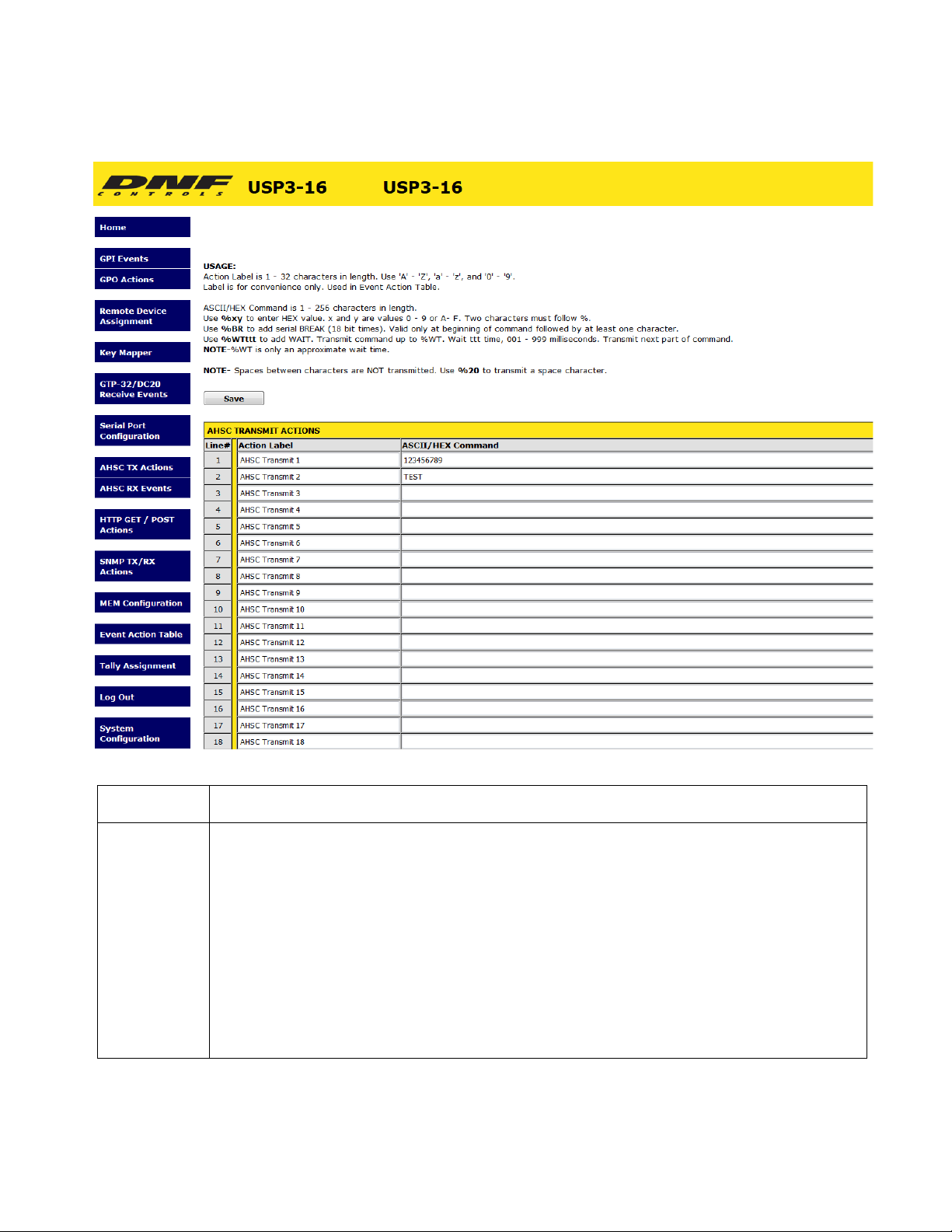
12. AHSC TRANSMIT ACTION
Action Label Enter any 32 characters. This label is used in the Event Action Table.
ASCII/ HEX
Command
USP3 User Manual Page 18 of 46
The ASCII/HEX Command is 1 - 256 characters in length.
Use %yz to enter a HEX value. ‘y’ and ‘z’ are values 0 - 9 or A-
Two characters must follow %.
F.
Use %WTttt to add a WAIT time, 001 - 999 milliseconds. Three numbers must follow %WT.
The characters preceding %WT are sent immediately. The characters after %WTttt are sent
after the wait time expires. More than one %WT can be included in a command. NOTE%WT
For SERIAL only- Use %BR to add a BREAK character as the first transmitted character.
NOTE- Spaces between characters are NOT transmitted. Use %20 to transmit a
space
is only an approximate wait time.
character.

13. AHSC RECEIVE EVENT
Event Label Enter any 32 characters. This label is for convenience only and is used in the Event Action
Table.
USP3 User Manual Page 19 of 46

ASCII/ HEX
Receive Data
Enter 1- 16 characters and/or bit patterns to match against received serial data.
The received characters must exactly match the order and value of the entered patterns. If a
received
and the match
elapses between received
process begins again.
Use %yz to enter a HEX character. ‘y’ and ‘z’ are values 0 - 9, A - F, or 'X' (don’t care).
Enter %Xz to match only the z part of the HEX character. Enter %yX to match only the y
part of the
Use #yyyyyyyy to match an exact bit pattern. ‘y’ values are '0', '1', or 'X' (don't care). For
example,
on the far left.
Use <yyyyyyyy to match any bit in the bit pattern. ‘y’ values are '0', '1', or 'X' (don't care).
For
on the far left.
Use '!' to NOT match a character pattern. For example: Event Label= TEST. Receive pattern=
!A.
If any character other than 'A' is received, then TEST event is ON. If 'A' is received, then
TEST event
NOTE- Spaces between patterns are ignored. Use %20 to match a space character.
Pattern matching examples can be found in the back of this manual.
character does not match the entered pattern, all previous matches are discarded
process begins again with the first entered pattern. If more than 1 second
characters, all previous matches are discarded and the match
HEX character. Enter %XX to ignore the received value.
enter #0XXX1XXX to match bit7= 0 and bit3= 1. Bit0 is on the far right. Bit7 is
example, enter <0XXX1XXX to match bit7=0 or bit3= 1. Bit0 is on the far right. Bit7 is
is OFF. Use !y, !%yz, or !#yyyyyyyy to specify a NOT pattern match.
(Remainder of page is blank)
USP3 User Manual Page 20 of 46

14. HTTP GET / POST ACTIONS
The Hypertext Transfer Protocol (HTTP) is designed to enable communications between clients and servers. HTTP works as a request-response protocol between a client and server.
Two commonly used methods for a request-response between a client and server are: GET and POST.
GET - Requests data from a specified resource
POST - Submits data to be processed to a specified resource
Action Label Enter any 32 characters. This label is used in the Event Action Table.
Mode
Path
Ver
Header
Value
Use the dropdown to select between HTTP “POST” and HTTP “GET”.
Define the path of the HTTP “POST” or “GET”.
Use the dropdown to select between “HTTP/1.0” and “HTTP/1.1”.
Enter the header data of the HTTP “POST” or “GET”.
Enter the value data of the HTTP “POST” or “GET”.
USP3 User Manual Page 21 of 46

Content-Type Options available:
• Text/plain
• Text/HTML
• Application/XML
• Application/JSON
• Application/x-www-form-urlencoded
Data
Enter the data of the HTTP “POST” or “GET”.
(Remainder of page is blank)
USP3 User Manual Page 22 of 46

15. SNMP TX/RX ACTIONS
Event/Action
Label
Enter any 32 characters. This label is for convenience only and is used in the Event
Action
Table.
Community Community string is 1 - 32 characters in length. Typical value is 'public'.
Command SET, GET, GET RESPONSE or TRAP (RX ONLY)
USP3 User Manual Page 23 of 46

Object
Identifier
(OID)
The OID is 8 - 256 decimal values in length entered in dot notation. Only decimal values
are accepted.
ie: 1.22.333.4.55.666.7.88. Maximum entered decimal value is 99999999.
Value Type
OID Value Type:
OID Value
Integer:
Octet Integer
Enter decimal value 0 - 999999 for OID value.
Octet String: Enter 16 alphanumeric characters.
NULL: Set to NULL when no OID value is entered.
ANY: A n y of the options avail ab le.
: Enter decimal value 0 - 999999 for OID value.
USP3 User Manual Page 24 of 46

16. MEM CONFIGURATION
MEM Label Enter any 32 characters. This label is for convenience only and is used in the Event
Action
Radio Group
MEM’s are used to save an Event In's ON or OFF state and trigger an ON or OFF ACTION. MEMs are
also used on the Tally Assignment web page to control LCD Key text and color.
In the Event Action Table, an Event IN can turn ON, turn OFF or TOGGLE the state of a MEM. Also, a
MEM can be used as an Event IN to trigger an ON or OFF ACTION.
For example, a MEM can be used to convert a momentary event into a latching tally. VTR Play status turns
on MEM 1. VTR Stop status turns off MEM 1. The LCD Key tallying MEM 1 displays PLAY when MEM 1
is on and STOP when MEM 1 is off.
Please refer to section 18 for example of MEMs FLIP FLOP and RADIO GROUP.
USP3 User Manual Page 25 of 46
Select from “RG1 – RG6” to put the selected mem into a radio group.
Table.

17. EVENT ACTION TABLE
On an Event Action Table line, select an EVENT IN on the left side of the table and then select an ACTION on
the right side. Some events only support ON ACTIONS, so the OFF ACTION entries will be grayed out.
One EVENT IN can trigger more than one ACTION. Select the same EVENT IN on multiple lines and then
select an ON or OFF ACTION on each line.
Only EVENTs and ACTIONs associated with the Remote Device’s Device Type or Connection Type will be
displayed in the drop down menus. If the desired event or action is not displayed, then go to the Remote
Device Assignment web page and change the Device Type or Connection Type for the Remote Device.
There are 16 Sequence Timers. Use each Sequence Timer event number in multiple lines as the Event Type
to create a sequence of actions. The first Sequence entry from the top of the table will be the first sequence
action. The next Sequence entry from the top of the table will be the next sequence action. The Event column
time is the delay before that line’s action will execute. Use Sequence Start action to start a sequence. Use
Sequence Stop/ Reset to stop a sequence. The Sequence will always start at its first line.
An “Overrid e Loc al Acti on ” link lets users execute the ON or OFF Actions of a given Event Action Table line
without triggering the source event.
USP3 User Manual Page 26 of 46

None (Greys out line)
Source
E
V
E
N
T
Event
Type
I
N
Local Event
Remote Device Event
Serial
Local:
Keypress Keypress changed from OFF to ON. The selected ON ACTION will execute.
Keypress changed from ON to OFF. The selected OFF ACTION will execute
GPI GPI changed from OFF to ON. The selected ON ACTION will execute.
GPI changed from ON to OFF. The selected OFF ACTION will execute
MEM
MEM changed from OFF to ON. The selected ON ACTION will execute.
MEM changed from ON to OFF. The selected OFF ACTION will execute
Remote: AHSC Receive Event
Sequence Timer
The sequence timer’s time has expired. Only ON ACTION is executed.
The timer automatically restarts for the time period of the next sequence event in the
table. After the last sequence event in the table has expired and its ON ACTION
executed, the timer automatically restarts for the time period of the first sequence event
in the table.
MANUAL EVENT – Sequence time is ignored.
Continuous Timer
The Continuous timer’s time has expired. Only ON ACTION is executed.
The timer automatically starts once “Save” is pressed in the Event Action table. After the
timer has expired and its ON ACTION executed, the timer automa tically restarts for the
time period setup in the Event Action table.
A successful pattern match has occurred for the selected AHSC Receive Event pattern
on the selected Remote Device. Only ON ACTION is executed.
If the AHSC Receive Event pattern is assigned to multiple Remote Devices, only the
ON ACTION associated with the Remote Device that received the successful match will
execute.
GTP-32/DC20 Receive ( Only available for Device Type “GTP-32/DC20”)
An Event Label was received that matched the selected GTP-32/DC20 Event Label on
the selected Remote Device. Only ON ACTION is executed.
If an Event Label is assigned to multiple Remote Devices, only the ON ACTION
associated with the sending Remote Device will execute.
USP Keypress ( Only available for Device Type “USP”)
An event (Keypress or GPI) was received that matched the selected event on the
selected Remote Device.
GPI Number, AHSC Receive Event Label, Ethernet Receive Event Label, or GTP-32/DC20 Event
Event
USP3 User Manual Page 27 of 46
Label, Sequence Timer time period.
The display labels in the drop down menus are the same user entered labels on the event web pages

Rem
ote:
Local /
Remote
Execute Action on Local USP3
Execute Action on Remote Device
O
N
A
C
T
O
N
Type
I
Local: GPO Do Nothing
Turn GPO ON
Turn GPO OFF
MEM Do Nothing
Turn MEM ON
Turn MEM OFF
Sequence Start
Start identified sequence at its first line in the Event Action Table.
Sequence Stop / Reset
Immediately stop sequence.
Sequence Toggle
Toggle current sequence.
Sequence Repeat
Repeat current sequence
Sequence Next
Allows Manual Sequence operation.
Key Enable Turn ON Key Enable
Turn OFF Key Enable
Toggle Key Enable
Redundant Turn ON Redundant Mode
Turn OFF Redundant Mode
Toggle Redundant Mode
Main/Backup Select MAIN
Select BACKUP
Toggle between MAIN/BACKUP
Restart Timer
Restarts the currently selected timer in the Event Action Table.
AHSC Transmit Action
Transmit the selected AHSC Action command. If command contains
WAIT (%WT), then transmit all characters prior to %WT, wait for the time
period defined by %WT, and then transmit the remaining characters or
until the next %WT. A command may contain more than one %WT.
GTP-32/ DC20 (Only available for Device Type “GTP-32/DC20”)
Transmit GPI ON (as a Key Press), GPI OFF (as a Key Release), GPO
ON, and GPO OFF messages to a GTP-32 /DC20 Remote Device.
USP (Only available for Device Type “USP”)
Transmit a Key Press to a Remote USP panel.
Action
Label
USP3 User Manual Page 28 of 46
GPO Number
AHSC Transmit Action

Local /
Rem
ote:
Action
Remote
O
F
F
A
C
T
I
O
N
Type
Execute Action on Local USP3
Execute Action on Remote Device
Local: GPO Do Nothing
Turn GPO ON
Turn GPO OFF
MEM Do Nothing
Turn MEM ON
Turn MEM OFF
Sequence Start
Start identified sequence at its first line in the Event Action Table.
Sequence Stop / Reset
Immediately stop sequence.
Sequence Toggle
Toggle current sequence.
Sequence Repeat
Repeat current sequence
Key Enable Turn ON Key Enable
Turn OFF Key Enable
Toggle Key Enable
Redundant Turn ON Redundant Mode
Turn OFF Redundant Mode
Toggle Redundant Mode
Main/Backup Select MAIN
Select BACKUP
Toggle between MAIN/BACKUP
Restart Timer
Restarts the currently selected timer in the Event Action Table.
AHSC Transmit Action
Transmit the selected AHSC Action command. If command contains
WAIT (%WT), then transmit all characters prior to %WT, wait for the time
period defined by %WT, and then transmit the remaining characters or
until the next %WT. A command may contain more than one %WT.
GTP-32/ DC20 (Only available for Device Type “GTP-32/DC20”)
Transmit GPI ON (as a Key Press), GPI OFF (as a Key Release), GPO
USP (Only available for Device Type “USP”)
GPO Number
AHSC Transmit Action
Label
USP3 User Manual Page 29 of 46
ON, and GPO OFF messages to a GTP-32 /DC20 Remote Device.
Transmit a Key Press to a Remote USP panel.

18. TALLY ASSIGNMENT
Key Number The USP3 key number.
Tally Type Local- Follow Key, Follow GPI, Follow GPO, Follow ENABLE Key, Follow Memory
Location (MEM), Follow Sequence (SEQ)
Remote- Tally Remote Device: USP, GTP-32/DC20, Other
Tally Source Local Follow Key- Tally is ON when key is pressed
Tally is OFF when key is released
Follow GPI- Tally is ON when GPI is ON
Tally is OFF when GPI is OFF
Follow GPO- Tally is ON when GPO is ON
Tally is OFF when GPO is OFF
Follow ENABLE- Tally is ON when ENABLE is ON
Tally is OFF when ENABLE is OFF
Follow MEM- Tally is ON when MEM is ON
Tally is OFF when MEM is OFF
Follow SEQ- Tally is ON when Sequence is in progress
OFF when Sequence is not running
Tally is
USP3 User Manual Page 30 of 46

Tally Source Remote Follow remote USP GPI or GPO-
Tally is ON when remote GPI/GPO is ON
OFF when remote GPI/GPO is OFF
Follow GTP-32 or DC-20 Event Label
Tally is ON when Event Label state is ON
OFF when Event Label state is OFF
Tally is
Tally is
Tally Number
Tally
Extended Follow GTP/DC- For use with “ET_” Event Labels only
Formatted: ET_NameField_StatusField
The Extended Tally is off when received ET Event Label matches Name
but does not match any Status entries assigned to key or matches
ET1Tally is ON when the received Event Label matches the Name Field
Status Field for ET1 and the Event Label is ON
ET2 through ET4 Tally is ON when the received Event Label matches
Field and Status Field for ET2 through ET4, respectively, and
ON
Follow GTP/DC User Register- For use with “UR_” Event Labels only
The UR Event Label is OFF when User Register value does not match
entries for key or matches OFF entry value
UR1Tally is ON when the received User Register value matches the
value entry
UR2 through UR4 Tally is ON when the received User Register value
the UR1 through UR4 value entry, respectively
GPI / GPO Number
SNMP Table Entry Number
AHSC Table Entry Number
OFF / ON
OFF / ET1, ET2, ET3, ET4 for Extended Tallies
OFF / UR1, UR2, UR3, UR4 for User Register Tallies
Field
OFF entry
and
the Name
the Event Label is
any UR
UR1
matches
Dark, Red, Green, Amber
Flashing Red, Flashing Green, Flashing Amber
Blinking Red, Blinking Green, Blinking Amber
Tally Color
Text
Font Size
Event Label
Value
USP3 User Manual Page 31 of 46
Dim Red, Dim Green, Dim Amber
Dim Flashing Red, Dim Flashing Green, Dim Flashing Amber
Dim Blinking Red, Dim Blinking Green, Dim Blinking Amber
Text displayed on key face for each tally entry
Small: 3 rows x 6 characters per row
Normal: 2 rows x 4 characters per row
Big: 1 row x 3 characters per row
Manually enter, or cut & paste, the Event Label from the GTP-32’s or DC20’s Event
Notification Table. The event label is case sensitive, may not contain spaces, and
exactly match the Event Notification Table entry. (Refer to the GTP-32 or
must
DC20 User
Enter User Register value to match
Manual.)

19. EXAMPLES: RECEIVE PATTERN MATCHING
NOTE- ASCII and HEC data can be mixed in a user entered pattern. For simplicity only, the examples
do not mix ASCII or HEX in a user entered pattern.
ASCII Examples
User Entered Pattern Received ASCII Data Notes
ABCD ABCDEFG Successful pattern match of first 4 received characters
ABCD 1234ABCDEFG Successful pattern match of 5th , 6th, 7th, and 8
th
received
characters
ABCD 1234A5BCDEFG No pattern match. User entered pattern must be received
as entered.
A %XX C D
NOTE- spaces are not
included in pattern
match
ABCD
ACCD
AJCD
A2CD
The value of the second character in the
a wildcard, so it can be
any character.
A successful pattern match will result if the
fourth characters are correct.
All four received character patterns are a
pattern, %XX, is like
first, third and
successful
pattern match.
A %XX C D 1234ABCDEFG
Successful pattern matches.
1234A5CDEFG
4AKCDE
A %XX C D ACD No pattern match. Four characters must be received.
Hex Examples (Base 16 Numbering)
User Entered Pattern Received Hex Data
(spaces for display only)
%12 %34
12 34
12 34 56 78
Notes
Successful pattern matches for hexadecimal
34.
values 12 and
56 78 12 34 9A
56 78 12 34
%X2 12
32
52
A2
The first half of the received Hex value is like
can be any value. Only the
entered
value.
second half must match the user
Successful pattern matches.
a wildcard and
%12 %4X 12 43
12 4A
12 49 56
98 12 49
%12 %4X 12 34
The second half of the received Hex value is
and can be any value. Only
entered
value.
the first half must match the user
Successful pattern matches.
No pattern match.
like a wildcard
12 84
12 56
USP3 User Manual Page 32 of 46

Binary Examples (Base 2 Numbering)
User Entered Pattern
Received Binary Data
Notes
User Entered Pattern Received Binary Data
(spaces for display only)
#0XXX1XXX
01011000 Bit 7 is immediately after the ‘#’. Bit 0 is on the far right.
Bit7 = 0, Bit3= 1
All other bits are “Don’t care”
Notes
A pattern match occurs only when Bit 7= 0
The received data must exactly
match these identified bit
values for a match.
The values of the other 6 bits are ignored.
match.
and Bit3= 1.
Successful
#0XXX1XXX
01111111
Successful pattern matches.
00001000
01101001
#0XXX1XXX 10001000 No pattern match. Bit 7, on the far left is ‘1’. It must be ‘0’
to match.
#0XXX1XXX 00000000 No pattern match. Bit 3 is ‘0’. It must be ‘1’ to match.
<0XXX1XXX
Bit7 = 0, Bit3= 1
All other bits are “Don’t care”
(spaces for display only)
01011000 Bit 7 is immediately after the ‘#’. Bit 0 is on the far right.
A pattern match occurs when Bit 7= 0 or
one of the bits in the received
data must match.
The values of the other 6 bits are ignored
Bit3= 1. Only
Successful
match.
<0XXX1XXX
Bit7 = 0, Bit3= 1
All other bits are “Don’t care”
<0XXX1XXX
11111111 Received Bit 7 =1. Received Bit 3= 1.
At least one identified bit, Bit 3, matches.
pattern match.
10000000 Received Bit 7 =1. Received Bit 3= 0.
Successful
Bit7 = 0, Bit3= 1
All other bits are “Don’t care”
<0XXX1XXX
Bit7 = 0, Bit3= 1
All other bits are “Don’t care”
<0XXX1XXX
Bit7 = 0, Bit3= 1
All other bits are “Don’t care”
USP3 User Manual Page 33 of 46
11111111
00000000
01010101
10101010
11110111
10000000
11010101
10100010
None of the identified bits match the user
pattern. No pattern match.
Successful pattern matches.
No pattern match.
entered

ASCII Examples
User Entered Pattern Received ASCII Data Notes
!A B A pattern match is successful when the received character is
any character except
‘A’.
!A AAAAAA All of the received characters are ‘A’. No pattern match.
!A AB The second character is not an ‘A’. The received data is a
successful pattern match.
!A BA The first character is not an ‘A’ and is a successful pattern
match. The received data
is a successful pattern match.
!A BC No character is an ‘A’. Successful pattern
match.
!AB AB The first character can be any character except ‘A’. The
second character must be
‘B’.
No pattern match
!AB
CB
DB
ZB
The first character can be any character
second character must be
‘B’.
except ‘A’. The
Successful pattern match
!AB CD The first character can be any character except ‘A’. The
second character must be
‘B’.
No pattern match
Hex Examples (Base 16 Numbering)
User Entered Pattern Received Hex Data Notes
!%12 12 A pattern match is successful when any value is received
except 12.
No pattern match.
!%12 34 22 34 A pattern match is successful when any value is received
except 12, immediately
followed by 34
Successful pattern match.
!%12 34 11 34
Successful pattern matches.
21 34
9F 34
87 34
!%12 34 11 12 34 No pattern match
!%12 34 11 22 34
Successful pattern matches
11 45 34 56
USP3 User Manual Page 34 of 46

20. EXAMPLES: SEQUENCES
When the Sequence Timer’s event time expires, the associated ON Action will execute and then the timer for
the sequence’s next entry in the Event Action Table will start.
Upon receipt of a Sequence Start action, the timer for the Sequence’s first entry in the Event
start.
Upon receipt of a Sequence Stop action, the sequence will immediately stop. The sequence
progress will halt without executing. The next Start action will cause the sequence to
the Event Action Table.
When the last Sequence action executes, the sequence will automatically turn off and stop
last Sequence action is Sequence Start, the sequence will loop until a Sequence
Example #1 Wait for Sequence Start action and then play sequence until end and stop.
Event Type Event Description
Key Press 1 Sequence 1 Start action
Sequence 1 Timer 100ms Delay 100ms and then execute assigned ON Action
Sequence 1 Timer 1 sec Delay 1 second and then execute assigned ON Action
Sequence 1 Timer 10 sec Delay 10 seconds and then execute assigned ON Action
Sequence 1 Timer 100ms Sequence 1 Start action
Key Press 2 Sequence 1 Stop action
Stop is received.
Action Table will
entry in
start at its first entry in
executing. If the
USP3 User Manual Page 35 of 46

21. EXAMPLES: MEM / FL IP FLOP
To setup a FLIP FLOP action the use of a MEM is required. A source events (GPI or Keypress) ON
action will FLIP FLOP the action of two GPO’s.
The selected MEM that is being toggled will need to be setup in following manner to trigger the FLIP
FLOP action.
ON ACTION:
OFF ACTION:
Example #1 MEM FLIP FLOP GPO 1 and 2
TURN ON GPO_1, TURN OFF GPO_2
TURN OFF GPO_1, TURN ON GPO_2
USP3 User Manual Page 36 of 46

22. EXAMPLES: MEM / RADIO GROUP TALLY
To setup a MEM based RADIO GROUP TALLY the use of MEMs is required.
First a MEM/s will need to be assigned to a Radio Group (RG1 – RG6)
A source events (GPI, Keypress or Serial Event) ON action will turn ON the MEM/s associated with the
Radio Group. MEM ON must be selected as the ON action for the Radio Group functionality to work
properly.
Assign each MEM to a specific USP3 Key in the Tally Assignment page
.
When a Source Event triggers on the USP3, the MEM tied to this source event will turn ON. This MEM
ON action will cause its Key tally to turn ON all oth e r Key tallies in the same Radio Group will turn
OFF.
USP3 User Manual Page 37 of 46

23. EXAMPLES: GPO MOMENTARY RADIO GROUP
To setup a GPO Momentary Radio Group the use of MEMs is required.
First, in the GPO actions page set the operating mode of each GPO you will be using to “momentary”
and set the desired momentary on-time.
Next, in the MEM Configuration page assign a MEM to each GPO that you will be using for your Radio
Group. Under the Radio Group Dropdown, assign all MEM’s to the same radio group (RG1 – RG5)
A source event (GPI, Keypress or Serial Event) ON action will turn ON the MEM/s and GPO’s associated
with the Radio Group. MEM ON must be selected as the ON action for the Radio Group functionality to work
properly.
(Continued on Next Page)
USP3 User Manual Page 38 of 46

Assign each MEM to a specific USP3 Key in the Tally Assignment page
.
When a Source Event triggers on the USP3, the MEM tied to this source event will turn ON. This MEM
ON action will cause its Key tally to turn ON all other Key tallies in the same Radio Group will turn
OFF.
USP3 User Manual Page 39 of 46

24. SPECIFICATIONS
*Illustration below is Rear Panel of USP3-8 & USP3-16:
REAR PANEL CONNECTORS
POWER 1: +12V DC, 3.0Amps
POWER 2: Optional power supply for redundant power
RESET Switch: Press to reset USP3
ETHERNET: RJ45 100baseT, Full Duplex
S1 Switch:
SERIAL CONNECTOR:
Press and hold 10 seconds to reset IP address to 192.168.10.217 and
configuration to factory default
RS232 DTE RS422 Controller RS422 Device
Pin
1
N/C
2
RxD Receive A (-) Transmit A (-)
3
TxD Transmit B (+) Receive B (+)
4
Tied to 6 Receive Common Receive Common
5
Ground N/C N/C
6
Tied to 4 Transmit Common Transmit Common
Frame Ground Frame Ground
7
N/C Receive B (+) Transmit B (+)
8
N/C Transmit A (-) Receive A (-)
9
N/C Frame Ground Frame Ground
USP3 User Manual Page 40 of 46

REAR PANEL CONNECTORS
GPI CONNECTOR 1-8:
Opto-isolator Inputs
NOTE:
GPI (+) is opto-isolator anode
GPI (-) is opto-isolator cathode
To WET GPIs:
Connect GPI + to nearby +V
pin.
Connect GPI – to Ground to
turn on GPI.
Pin # Description Pin # Description
17
20
23
GPI 8 +
GPI 6 +
GPI 4 +
GPI 2 +
1 Ground 14
2 GPI 8 ─ 15 +V
3 +V 16 GPI 7 ─
GPI 7 +
4
5 GPI 6 ─ 18 +V
6 +V 19 GPI 5 ─
GPI 5 +
7
8 GPI 4 ─ 21 +V
9 +V 22 GPI 3 ─
GPI 3 +
10
11 GPI 2 ─ 24 +V
12 +V 25 GPI 1 ─
GPI 1 +
13
GPI CONNECTOR 9-16:
Opto-isolator Inputs
NOTE:
GPI (+) is opto-isolator anode
GPI (-) is opto-isolator cathode
Pin # Description Pin # Description
17
GPI 16 +
GPI 14 +
1 Ground 14
2 GPI 16 ─ 15 +V
3 +V 16 GPI 15 ─
GPI 15 +
4
To WET GPIs:
Connect GPI + to nearby +V
pin.
Connect GPI – to Ground to
turn on GPI.
5 GPI 14 ─ 18 +V
6 +V 19 GPI 13 ─
GPI 13 +
7
8 GPI 12 ─ 21 +V
9 +V 22 GPI 11 ─
GPI 11 +
10
20
23
GPI 12 +
GPI 10 +
11 GPI 10 ─ 24 +V
12 +V 25 GPI 9 ─
USP3 User Manual Page 41 of 46
13
GPI 9 +

REAR PANEL CONNECTORS
GPO CONNECTOR 1-8:
Isolated Relay
Contact Clo s ures
To WET GPOs:
Connect external power supply
output to Common Bus, pin #1.
Connect GPO commons to
nearby Common Bus pins
Pin # Description Pin # Description
1 Common Bus 14 GP0 8 N.O
2 GPO 8 Common 15 Common Bus
3 Common Bus 16 GPO 7 N.O.
4 GPO 7 Common 17 GPO 6 N.O.
5 GPO 6 Common 18 Common Bus
6 Common Bus 19 GPO 5 N.O.
There is no need to connect
power supply Ground to GPO
connector
7 GPO 5 Common 20 GPO 4 N.O.
8 GPO 4 Common 21 Common Bus
9 Common Bus 22 GPIO 3 N.O.
10 GPO 3 Common 23 GPO 2 N.O.
11 GPO 2 Common 24 Common Bus
12 Common Bus 25 GPO 1 N.O.
13 GPO 1 Common
GPO CONNECTOR 9-16:
Pin # Description Pin # Description
Isolated Relay
Contact Clo s ures
To WET GPOs:
Connect external power supply
output to Common Bus, pin #1.
Connect GPO commons to
nearby Common Bus pins
There is no need to connect
power supply Ground to GPO
connector
1 Common Bus 14 GP0 16 N.O
2 GPO 16 Common 15 Common Bus
3 Common Bus 16 GPO 15 N.O.
4 GPO 15 Common 17 GPO 14 N.O.
5 GPO 14 Common 18 Common Bus
6 Common Bus 19 GPO 13 N.O.
7 GPO 13 Common 20 GPO 12 N.O.
8 GPO 12 Common 21 Common Bus
9 Common Bus 22 GPIO 11 N.O.
10 GPO 11 Common 23 GPO 10 N.O.
11 GPO 10 Common 24 Common Bus
12 Common Bus 25 GPO 9 N.O.
13 GPO 9 Common
USP3 User Manual Page 42 of 46

25. USP-S24 Key Layout & Rear Panel
USP3 User Manual Page 43 of 46

26. USP3-8D Key Layout & Rear Panel
USP3 User Manual Page 44 of 46

27. USP3-SHOTBOX Key Layout & Rear Panel
1
13
25 14
1
13
25 14
1
13
25 14
1
13
25 14
1
6
GPI 1 - 8
GPI 9 - 16
GPO 1 - 8
GPO 9 - 16
Serial
ETHERNET
S1
Reset
POWER 2
POWER 1
Rear View
USP3 User Manual Page 45 of 46

28. DNF CONTROLS LIMITED WARRANTY
DNF Controls warrants its product to be free from defects in material and workmanship for a period of
one (1) year from the date of sale to the original purchaser from DNF Controls.
In order to enforce the rights under this warranty, the customer must first contact DNF’s Customer
Support Department to afford the opportunity of identifying and fixing the problem without sending the
unit in for repair. If DNF’s Customer Support Department cannot fix the problem, the
issued a Returned Merchandise Authorization number (RMA). The customer will
defective product prepaid to DNF Controls with the RMA number clearly indicated on the customer’s
shipping document. The merchandise is to be shipped to:
DNF Controls
19770 Bahama St.
Northridge, CA. 91324
USA
Failure to obtain a proper RMA number prior to returning the product may result in the return not
accepted, or in a charge for the required repair.
DNF Controls, at its option, will repair or replace the defective unit. DNF Controls will return the unit
prepaid to the customer. The method of shipment is at the discretion of DNF Controls,
Ground for shipments within the United States of America. Shipments to
be sent via air. Should a customer require the product to be returned
the return shipment will be billed to their freight account.
This warranty will be considered null and void if accident, misuse, abuse, improper line voltage, fire,
water, lightning or other acts of God damaged the product. All repair parts are to be supplied
Controls, either directly or through its authorized dealer network. Similarly, any repair
performed by either DNF Controls or its authorized dealer may void the warranty.
After the warranty period has expired, DNF Controls offers repair services at prices listed in the DNF
Controls Price List. DNF Controls reserves the right to refuse repair of any unit outside the
period that is deemed non-repairable.
DNF Controls shall not be liable for direct, indirect, incidental, consequential or other types of
resulting from the use of the product.
international customers will
in a more expeditious manner,
# # #
customer will be
then ship the
principally UPS
work not
being
by DNF
warranty
damage
USP3 User Manual Page 46 of 46
 Loading...