

Page 1

12843 Foothill Blvd. Suite C
Sylmar, California 91342
V: 818.898.3380
F: 818.898.3360
sales@dnfcontrols.com
Flex Control Network®
UABS-I
(Universal Automation Backup System - I)
Installation Manual
Rev. 1.00
Page 2

REVISION HISTORY
052308 1.00 First release
1 of 5
1
Flex Control Network
®
UABS-I Installation Manual
Page 3

TABLE OF CONTENTS
OVERVIEW............................................................................................ 3
1.
A...Universal Automation Backup System, UABS-I Overview............................ 3
B...UABS-I Configuration............................................................................ 4
2. DC20 INSTALLATION............................................................................ 5
3. DC20 CONNECTION DIAGRAM............................................................... 6
4. DC20 CONFIGURATION......................................................................... 7
A...IP Address Setup ................................................................................. 7
B...Subnet Mask Setup .............................................................................. 7
C...Gateway Address Setup ........................................................................ 7
D...Ethernet Link Speed Setup .................................................................... 8
5. DC20 SETUP.......................................................................................... 9
A...Set Password......................................................................................10
B...Set System Label ................................................................................11
C...Set System Time.................................................................................12
D...Additional Setups ................................................................................12
6. DC20 SERIAL CHANNEL SETUP............................................................ 13
A...Serial Protocol Assignment ...................................................................14
B...Serial Device Configuration...................................................................15
C...PHYSICAL SERIAL (PHY) PORT CONFIGURATION......................................17
7. CP20 INSTALLATION .......................................................................... 18
8. CONNECTION DIAGRAM...................................................................... 19
9. CP20 SETUP........................................................................................ 20
A...Set Password......................................................................................21
B...Set System Time.................................................................................22
C...Set System Label ................................................................................23
D...Set DNF Port Number ..........................................................................24
E...Set Ethernet Speed .............................................................................25
F. ..Install FTP Server Software on PC Computer ...........................................26
G...Configure FTP Client On CP20 ...............................................................26
H...Channel Assignment............................................................................28
I....Additional Setups................................................................................29
10. DNF CONTROLS LIMITED WARRANTY ................................................ 30
Flex Control Network® UABS-I Installation Manual
of 5
22
Page 4

1. OVERVIEW
A. Universal Automation Backup System, UABS-I Overview
The Universal Automation Backup System (UABS) provides affordable,
simple, easy-to-use, reliable playout control. UABS utilizes the existing
playlists from your automation or traffic system. It controls program and
commercial channel playout. You can manually build playlists and modify
existing lists. UABS is a reliable hardware based solution standing by
24/7, to make sure that you stay on the air.
In an emergency, UABS allows you to manually roll Program (clip or tape)
and still automate commercial break playout, OR automate both program
and commercial playout.
UABS supports one playlist, for a full or partial broadcast day, which
contains time triggered, follow-along, and manually controlled elements.
Also supports program segment playout and secondary GPOs. The playlist
can be modified at any time—adding and removing elements, appending
playlists — even while the list is playing out.
UABS-I FEATURES
• Import playlist files from most major automation and traffic systems
• Playout program and commercial on one video server channel
• Manually roll program clips (or tape) on one video server channel and
automate commercial breaks on a second server channel
• Supports time triggered, follow along, and manual playout elements
• Supports program segments and secondary GPOs
• Manually build playlists on UABS or import from text editor
• Supports As-Run Log and Discrepancy List
• Consists of one Control Point and one Device Controller
3 of 5
3
Flex Control Network
®
UABS-I Installation Manual
Page 5
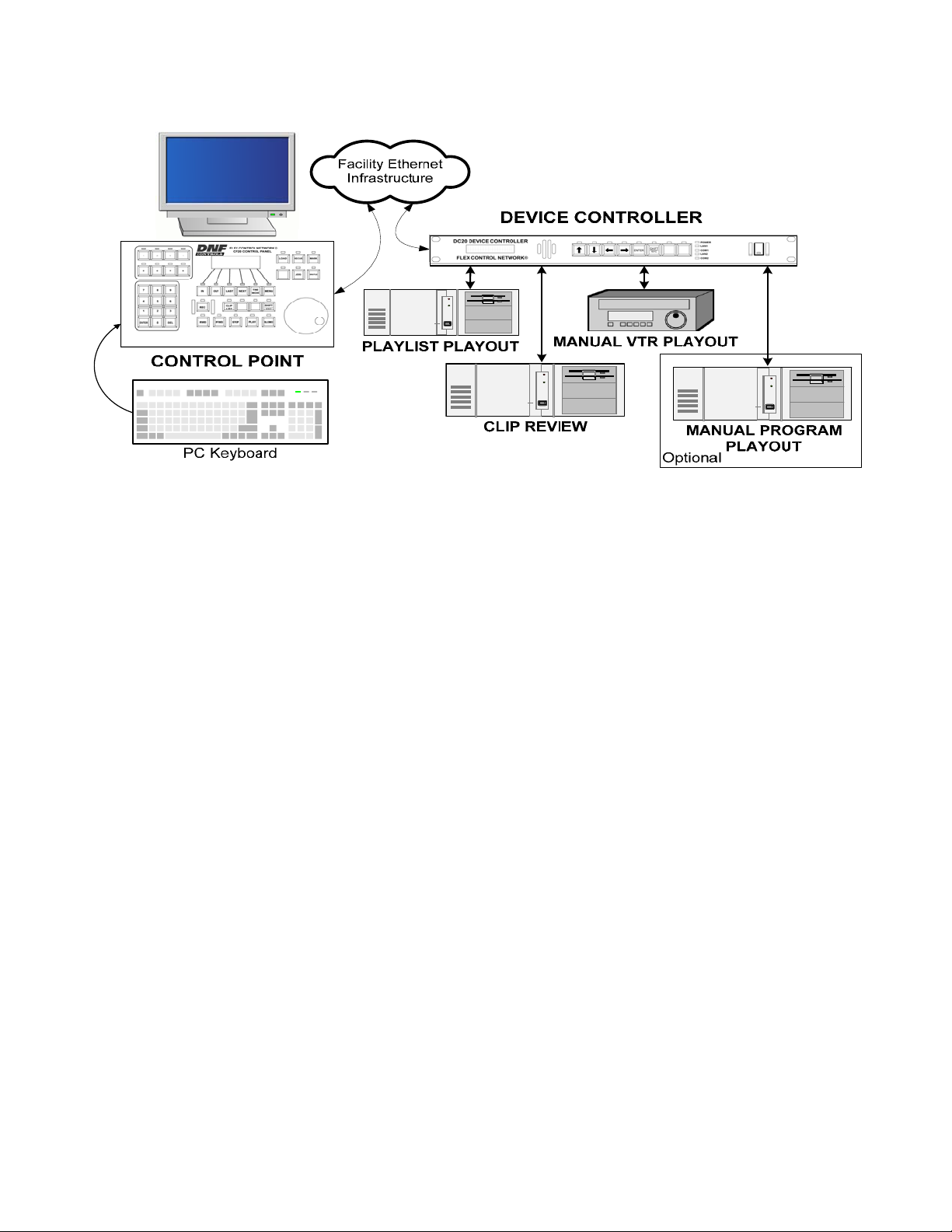
B. UABS-I Configuration
The Universal Automation Backup System is comprised of one DC20 Device
Controller and one CP20 Control Panel. (The VGA monitor, PC keyboard, video
server and Ethernet infrastructure is provided by the customer.)
The DC20 Device Controller is connected to two video server channels for playlist
playout, clip review, and has two additional channels available for manual program
play out on a video server channel or VTR. The CP20 Control Panel is connected to
the DC20 Device Controller thru an Ethernet connection.
In Master Control, the CP20 Control Panel, with external VGA monitor and keyboard,
is used for on-air playlist playout control and playlist editing.
Flex Control Network® UABS-I Installation Manual
of 5
44
Page 6

2. DC20 INSTALLATION
CAUTION
Do NOT apply AC voltage to power supply, then connect power supply to
DC20 Device Controller. Component damage may occur.
1) Connect Cat 5 cable to DC20 connector labeled “E-NET #1”. Connect
other end of Cat 5 cable to customer supplied Ethernet hub.
2) Plug one end of a standard 9-conductor, RS422 serial cable into the
Serial Port #1 connector on the rear of the DC20.
3) Plug the other end of the 9-conductor, RS422 serial cable into the
remote control connector on the VTR, DDR, or Video Server. Repeat
steps 2 and 3 for each serial port to be used for machine control.
4) Connect facility video reference to REF video connector on rear of
DC20. This is required for accurate play timing.
5) Connect facility time-of-day LTC to LTC Input Connector on rear of
DC20. This is required for accurate gang synchronization.
6) Connect power supply DB9 female connector to DC20 connector
labeled “POWER“.
7) Connect female side of power cable to supplied power supply.
8) Connect male side of power cable to AC voltage, 100 – 240.
9) Push DC20 power switch, located on front panel, to ON position. The
“O” on the power switch is the OFF position.
10) Front panel LEDs will flash during power up. When power up and
system initialization completes, the front panel LEDs will turn off and
the front panel display will show Model Number and Software Version.
Allow 45 seconds for power up and system initialization to complete.
No connection is required to the DIAGNOSTIC or VGA connectors on the rear
of the DC20.
CAUTION
Do NOT apply AC voltage to power supply, then hot plug power supply to
DC20 Device Controller. Component damage may occur.
5 of 5
5
Flex Control Network
®
UABS-I Installation Manual
Page 7
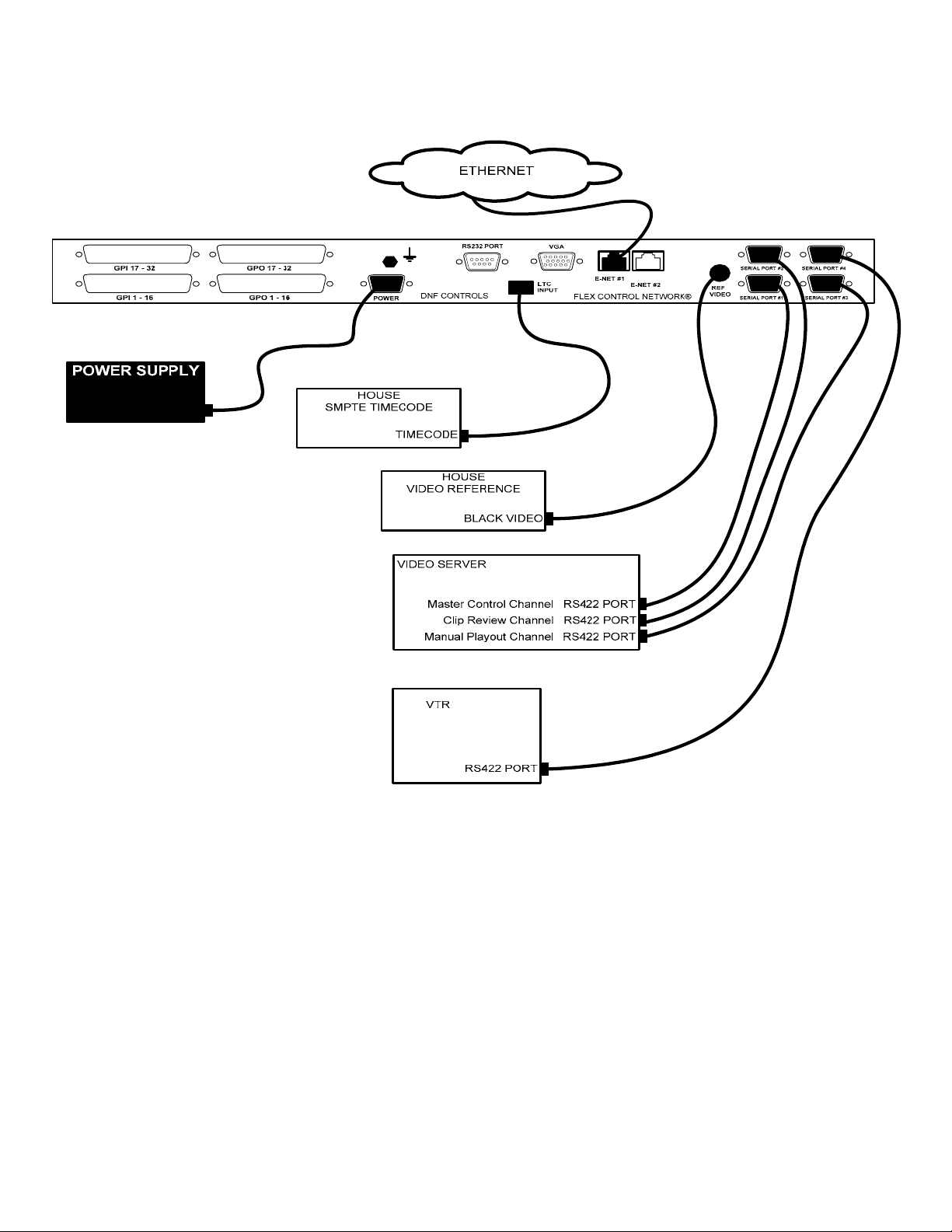
3. DC20 CONNECTION DIAGRAM
Flex Control Network® UABS-I Installation Manual
of 6
66
Page 8

4. DC20 CONFIGURATION
Configuration is required after initial installation.
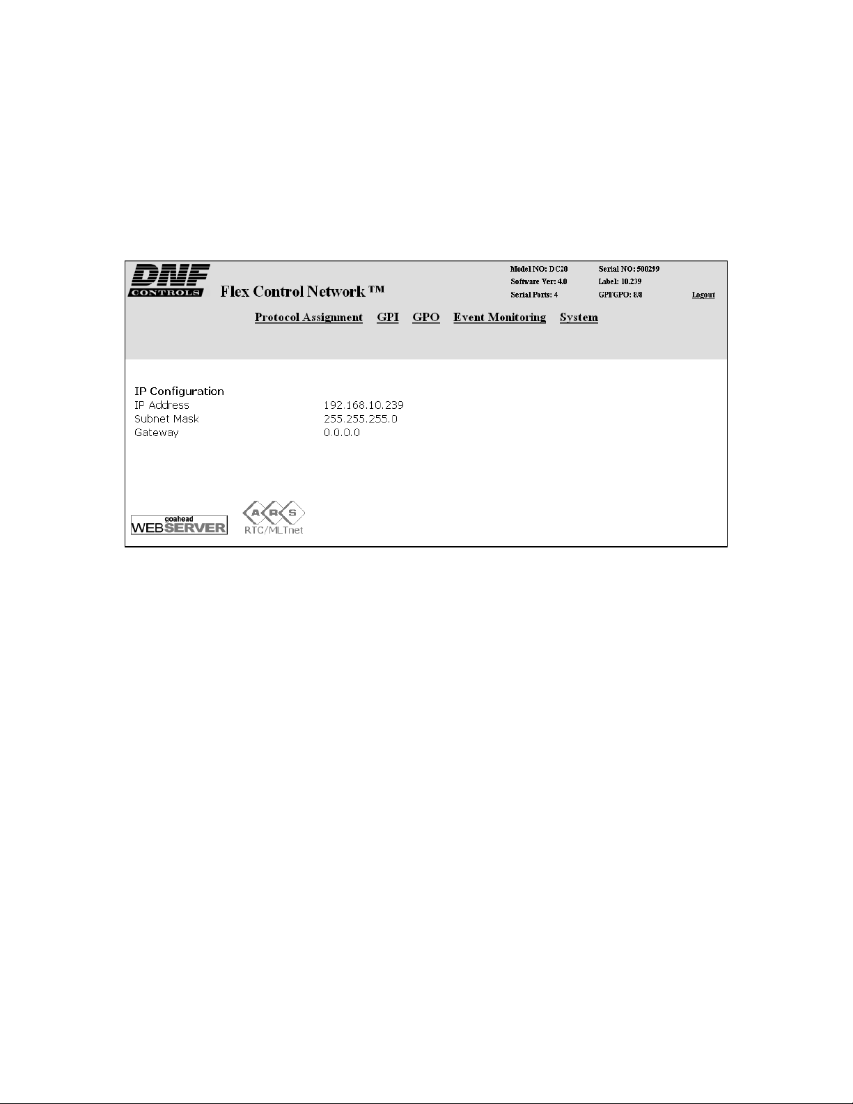
A. IP Address Setup
1) On the DC20 front panel, use ÏÐ keys to select “Current IP”.
2) Press ENTER key. Display will show current IP address with cursor in
far left column.
3) Use the ÏÐ keys to change number.
4) Use Í Î keys to move cursor position.
5) Press ENTER to save new IP address.
OR
Press ESC to exit without saving.
NOTE- New IP Address will take effect on next power up.
B. Subnet Mask Setup
1) On the DC20 front panel, use ÏÐ keys to select “Current Mask”.
2) Press ENTER key. Display will show current Subnet Mask with cursor
in far left column.
3) Use the ÏÐ keys to change number.
4) Use Í Î keys to move cursor position.
5) Press ENTER to save new Subnet Mask.
OR
Press ESC to exit without saving.
NOTE- New Subnet Mask will take effect on next power up.
C. Gateway Address Setup
1) On the DC20 front panel, use ÏÐ keys to select “Current Gateway”.
2) Press ENTER key. Display will show current Gateway address with
cursor in far left column.
3) Use the ÏÐ keys to change number.
4) Use Í Î keys to move cursor position.
5) Press ENTER to save new Gateway address.
OR
Press ESC to exit without saving.
NOTE- New Gateway Address will take effect on next power up.
7 of 7
7
Flex Control Network
®
UABS-I Installation Manual
Page 9

D. Ethernet Link Speed Setup
1) On the DC20 front panel, use ÏÐ keys to select “Ethernet Status”.
2) Press ENTER key. Display will show current speed selection.
3) Use the ÏÐ keys to change selection.
4) Select AUTO to use highest available speed.
5) Select 10Mbs for long Ethernet cable runs.
6) Press ENTER to save new IP address.
NOTE- New Ethernet speed selection will take effect immediately.
OR
Press ESC to exit without saving.
Flex Control Network® UABS-I Installation Manual
of 8
88
Page 10
5. DC20 SETUP
Setup is required after initial installation. This step may be performed at any
other time, as required.
Setup is performed using a computer running an off-the-shelf web browser
such as “Microsoft Internet Explorer” or “Netscape”. Connect the CAT5 cable
from the computer to the same Ethernet hub that the DC20 Device Controller
is connected to.
After launching the web browser, enter the IP address of the DC20 to be
setup. The DC20 Home Page will be displayed.
9 of 9
9
Flex Control Network
®
UABS-I Installation Manual
Page 11

A. Set Password
The default password, when shipped from the factory, is “controls”, all
lower case. The password is used to access all configuration screens.
Using the web browser-
1) From the DC20 Home Page, click on the “System” link. The System
page will be displayed.
2) Click on “Set Password”. The Set Password page will be displayed.
3) In the “Old password” entry box, enter the current password.
4) Note- When shipped from the factory, the default password is
“controls”, all lower case.
5) Enter the new password in the “New Password” entry box.
6) Enter the new password in the “Verify New Password” entry box.
7) Click on “Save” to save the new password.
OR, click on “Cancel” to exit without changing passwords.
Note- If the “New Password” entry and the “Verify New Password”
entry do not match, an error will be displayed.
Flex Control Network® UABS-I Installation Manual 1100 of 10
Page 12

B. Set System Label
The System Label is used to uniquely identify a DC20. This name is
associated with the IP address.
Using the web browser-
1) From the DC20 Home Page, click on the “System” link. The System
page will be displayed.
2) Click on “Set System Label”. The Set System Label page will be
displayed.
3) Enter any name made up of letters, numbers, or special characters, up
to 16 characters.
4) Click on “Save” to save the name entered in step 3).
OR, click on “Cancel” to exiting without changing the System Label.
1 of 11
111
Flex Control Network
®
UABS-I Installation Manual
Page 13

C. Set System Time
The system time is only used for error and event time stamping.
Using the web browser-
1) From the DC20 Home Page, click on the “System” link. The System
page will be displayed.
2) Click on “Set System Time”. The Set System Time page will be
displayed.
3) Using the drop down menus, set the current date and time.
4) Click on “Save” to save the entered date and time.
5) OR, click on “Cancel” to exit without saving.
D. Additional Setups
No additional setups are required in “Event Diagnostic” or “System
Maintenance” for normal operation. The LOGOUT lin k is used to log out of
the DC20 thereby disallowing any changes that are password protected.
Flex Control Network® UABS-I Installation Manual 1122 of 12
Page 14
6. DC20 SERIAL CHANNEL SETUP
Serial Channel Setup is required after initial installation. This step may be
performed at any other time, as required.
Serial Channel Setup is performed using a computer running an off-the-shelf
web browser such as “Microsoft Internet Explorer” or “Netscape”. Connect
the CAT5 cable from the computer to the same Ethernet hub that the DC20
Device Controller is connected to.
1) After launching the web browser, enter the IP address of the DC20 to
be setup. The DC20 Home Page will be displayed.
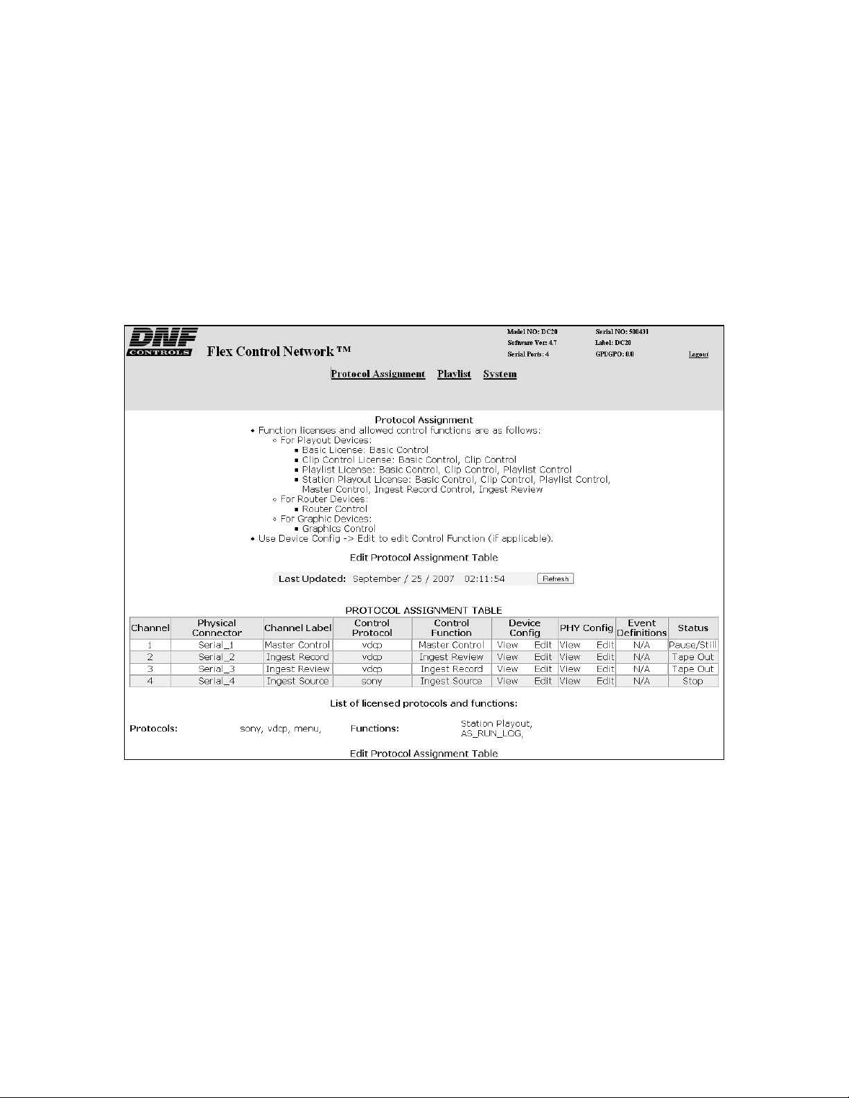
2) Click on the “Protocol Assignment” link at the top of th e page. The
Protocol Assignment Table will be displayed.
3 of 13
113
Flex Control Network
®
UABS-I Installation Manual
Page 15

A. Serial Protocol Assignment
1) Click on “Edit Protocol Assignment Table”. An editable version of the
table will be displayed.
2) On Channel #1:
a) Enter a channel label (up to 20 characters) for the Master Control
channel.
b) select “vdcp” from the Currently Licensed Control Protocol drop
down menu.
3) On Channel #2:
a) Enter a channel label (up to 20 characters) for the Clip Review
channel.
b) select “vdcp” from the Currently Licensed Control Protocol drop
down menu.
4) On Channels #3 and #4, enter a channel label.
5) On Channels #3 and #4, select the proper control protocol, for the
device under control.
6) Click on “SAVE” to save the entered values
OR
Click on “BACK” to exit without saving.
Flex Control Network® UABS-I Installation Manual 1144 of 14
Page 16

B. Serial Device Configuration
1) Click on the “Protocol Assignment” link at the top of th e page. The
Protocol Assignment Table will be displayed.
2) Click on “Edit” field under the "Device Configuration". An edit widow
will be displayed.
3) Click on drop down arrow field under the "Control Functions" field and
choose the control functionality (depending on licensed protocols).
4) Select: "Master Control" for the playlist playout channel
"Ingest Review" for the Clip Review channel
5) In the "Device Internal Latency" field, enter the play latency, from the
chart below, for your video server model.
DISK PREROLL Setup Chart for VDCP Protocol
Server Menu Settings
360 systems ON 10 frames
Avid Airspeed OFF 8 frames
Doremi ON 16 frames
EVS XT ON 2 frames
GV PDR, XP ON 40 frames
Disk
Preroll
Play Latency
5 of 15
115
GV K2 ON 10 frames
GV M-series, Turbo ON 20 frames
Leitch NX400 OFF 11 frames
Leitch NX3600, NX4200 OFF 6 frames
Omneon ON 60 frames
Flex Control Network
®
UABS-I Installation Manual
Page 17

6) Check the "Disk Preroll On" box as indicated in the chart above.
7) Click on field under "VDCP Port" and enter the VDCP port number.
NOTE- VDCP protocol requires that a Port number be assigned. This
port number is defined by the video server manufacturer.
8) Click on the dropdown arrow under "VDCP Port" and select INPUT for
record channels and OUTPUT for playback channels.
9) Check the "Extended IDs" box if the video server is configured to
support clips names greater than 8 characters in length.
10) Click on the dropdown arrow under "Time Base" and select DF or NDF.
Select the type of timecode used by the Video Server’s internal
timecode generator.
11) Under, select the model of video server that you are connected to. If
your video server is not listed in the drop down menu, select Other.
12) If connecting to a video server over Ethernet, enter the IP address of
the video server.
13) If using an Omneon video server, enter the name of the MediaPort you
are connecting to, the clip directory assigned to that MediaPort, as well
as the file extension being used.
14) Click on “SAVE” to save the entered values
OR
Click on “BACK” to exit without saving entered values.
Flex Control Network® UABS-I Installation Manual 1166 of 16
Page 18

C. PHYSICAL SERIAL (PHY) PORT CONFIGURATION
1) Click on the “Protocol Assignment” link at the top of th e page. The
Protocol Assignment Table will be displayed.
2) Click on “Edit” field under the "PHY Configuration". An edit widow will
be displayed.
3) Click on the drop down arrow under “Baud Rate” and chose “38400”.
4) Click on the drop down arrow under "Stop Bit" and chose “1”.
5) Click on the drop down arrow under "Parity" field and chose “ODD”.
6) Click on the drop down arrow under "Char Size" field and chose “8”.
7) Click on drop down arrow field under the "Operation Mode" field and
chose "CONTROLLER". (If the video server port is configured as a
controller port, then select "DEVICE".)
8) Click on “SAVE” to save the entered values
OR
Click on “BACK” to exit without saving entered values.
7 of 17
117
Flex Control Network
®
UABS-I Installation Manual
Page 19

7. CP20 INSTALLATION
CAUTION
Do NOT apply AC voltage to the power supply, before connecting the power
supply to CP20 CONTROL PANEL. Component damage may occur.
1) Connect a Cat 5 cable to CP20 CONTROL PANEL connector labeled “ENET #1”. Connect other end of the Cat 5 cable to customer supplied
Ethernet hub.
2) Connect power supply DB9 female connector to the CP20 CONTROL
PANEL connector labeled “POWER“.
3) Connect female side of AC power cable to the supplied power supply.
4) Connect male side of AC power cable to 100 – 240VAC.
5) Push the CONTROL PANEL power switch, located on rear panel, to ON
position. “O” on the power switch is the OFF position.
6) When power up and system initialization completes, the front panel
display will show Model Number and Software Version. Allow 25
seconds for power up and system initialization to complete.
CAUTION
Do NOT apply AC voltage to power supply, then hot plug the power supply to
the CP20 CONTROL PANEL. Component damage may occur.
Flex Control Network® UABS-I Installation Manual 1188 of 18
Page 20

8. CONNECTION DIAGRAM
9 of 19
119
Flex Control Network
®
UABS-I Installation Manual
Page 21

9. CP20 SETUP
Setup is required after installation. This step may be performed at any other
time, as required.
Setup is performed using a computer running an off-the-shelf web browser
such as “Microsoft Internet Explorer” or “Netscape”. Connect the CAT5 cable
from the computer to the same Ethernet hub that the CP20 is connected to.
After launching the web browser, enter the IP address of the CP20 to be
setup. The Home Page will be displayed.
Flex Control Network® UABS-I Installation Manual 2200 of 20
Page 22

A. Set Password
The default password, when shipped from the factory, is “controls”, all
lower case. The password is used to access all configuration screens.
Using the web browser-
1) From the Home Page, click on the “System” link. The System page
will be displayed.
2) Click on “Set Admin Password”. The Set Password page will be
displayed.
3) In the “Old password” entry box, enter the current password.
4) Note- When shipped from the factory, the default password is
“controls”, all lower case.
5) Enter the new password in the “New Password” entry box.
6) Enter the new password in the “Verify New Password” entry box.
7) Click on “Save” to save the new password.
OR
Click on “Cancel” to exit without chan ging the password.
Note: If the “New Password” entry and the “Verify New Password” entry
do not match, an error will be displayed.
1 of 21
221
Flex Control Network
®
UABS-I Installation Manual
Page 23

B. Set System Time
The system time is only used for error and event time stamping.
Using the web browser-
1) From the Home Page, click on the “System” link. The System page
will be displayed.
2) Click on “Set System Time”. The Set System Time page will be
displayed.
3) Using the drop down menus, set the current date and time.
4) Click on “Save” to save the entered date and time.
OR
Click on “Cancel” to exit with out saving.
Flex Control Network® UABS-I Installation Manual 2222 of 22
Page 24

C. Set System Label
The System Label is used to uniquely identify a CP20. This name is
associated with the IP address.
Using the web browser-
1) From the Home Page, click on the “System” link. The System page
will be displayed.
2) Click on “Set System Label”. The Set System Label page will be
displayed.
3) Enter any name made up of letters, numbers, or special characters, up
to 16 characters.
4) Click on “Save” to save the entered name.
OR
Click on “Cancel” to exiting without changing the System Label.
3 of 23
223
Flex Control Network
®
UABS-I Installation Manual
Page 25

D. Set DNF Port Number
The DNF Port Number is only changed from it default value (50000) when
the customer’s IT department has assigned a different port number to
allow the CP20 and DC20 communication to pass through their computer
network’s firewalls. Please consult the IT department for the port number
value.
NOTE- All Flex Control Network units, on the same system, must be
assigned the same Port Number setting. If not, the units will not be able
to communicate with each other.
Using the web browser-
1) From the Home Page, click on the “System” link. The System page
will be displayed.
2) Click on “Set DNF Port Number”. The Set DNF Port Nu mber page will
be displayed.
3) Enter a valid Port Number.
4) Click on “Save” to save the entered DNF port number.
OR
Click on “Back” to exit without saving.
Flex Control Network® UABS-I Installation Manual 2244 of 24
Page 26

E. Set Ethernet Speed
The default password, when shipped from the factory, is “controls”, all
lower case. The password is used to access all configuration screens.
Using the web browser-
1) From the Home Page, click on the “System” link. The System page
will be displayed.
2) Click on “System Maintenance” Link, the System Maintenance page will
be displayed.
3) Click on “Set Ethernet Speed” Link, the Ethernet Speed Setting page
will be displayed.
4) Click on the Radio button to select the Ethernet speed, and then click
on the Apply button.
OR
Click on the Back button to exit without making any ch anges.
5 of 25
225
Flex Control Network
®
UABS-I Installation Manual
Page 27

F. Install FTP Server Software on PC Computer
The CP20 can import a playlist from a computer folder and append it to its
on-air playlist. The computer folder is located on a Windows® computer
and contains a copy of the primary automation system’s on-air playlist.
The CP20 connects to this remote computer and displays the contents of
the computer folder, allowing the Master Control Operator to view and
select a playlist file.
As Windows does not provide an FTP Server, the FTP Server software
“Filezilla Server” must be installed on the Windows computer. To download
this free FTP Server, go to www.filezilla-project.org
“Download Filezilla Server windows only”. Follow t he instructions to
download and install the software.
. Click on the link
G. Configure FTP Client On CP20
1) On the computer used to configure the CP20 and DC20, use NOTEPAD
or other simple text editor to create a “txt” file with the following
content:
On line #1, FTP SERVER’s IP address
On line #2, FTP Server’s Logon User name
(created as part of Filezilla installation)
On line #3, FTP Server’s Logon Password
(created as part of Filezilla installation)
For example:
192.168.10.118
myname
mypassword
2) Save the file as "FTP.txt" in a convenient location on the computer.
3) On the same computer, using a web browser, enter the IP address of
the CP20 to go to its home web page.
4) From the home page, click on SYSTEM link and enter the login
password “controls”, all lower case, without the double quotes (“”).
5) Click on the SYSTEM MAINTENANCE link and then the SYSTEM
SNAPSHOT link. Wait 60 seconds for the page to open. Do not reclick on SYSTEM MAINTENANCE.
6) To the left of the UPLOAD link, clink on the Destination drop down
arrow and select “config”.
7) Click on UPLOAD link, at the bottom of the page.
8) Click on ADD FILES and then navigate to the FTP.txt
step #1. Highlight FTP.txt
displayed in the file list to the right of ADD FILES.
and click on OPEN. FTP.txt will be
file created in
9) Enter the FTP Password “st5controls”, all lower case, without the
double quotes (“”).
10) Click on UPLOAD FILES to copy FTP.txt into the CP20.
NOTE- The CP20 does NOT need to be rebooted.
Flex Control Network® UABS-I Installation Manual 2266 of 26
Page 28

11) Test the FTP Server as follows:
a) Start Filezilla on the computer.
b) On the CP20 numeric keypadc) Press ‘1’, View/Edit Playlist
d) Press ‘7’, File
e) Press ‘7’, View Files
f) Press ‘3’, Get Remote File
g) The CP20 VGA will display “ftp:” follow ed by the IP address in
FTP.txt
The VGA will also show the directory of the remote computer. Use the
CP20 wheel and press ‘1’ to view the contents of a directory.
.
7 of 27
227
Flex Control Network
®
UABS-I Installation Manual
Page 29

H. Channel Assignment
The Channel Assignment Table Setup is performed using a computer
running an off-the-shelf web browser such as “Microsoft Internet Explorer”
or “Netscape”. Connect the CAT5 cable from the computer to the same
Ethernet hub that the CONTROL PANEL is connected to.
After launching the web browser, enter the IP address of the CP20 to be
setup. The Home Page will be displayed.
1) Click on the “Channel Assignment” link at the top of the page. The
Channel Assignment Table will be displayed.
Flex Control Network® UABS-I Installation Manual 2288 of 28
Page 30

2) Click on the “Edit Channel Assignment Table” link at the bottom of the
page. The Edit Channel Assignment Table will be displayed.
3) On Local Channel #1, click in the Remote IP address field and enter
the DC20’s IP address.
4) Click on the Remote Channel drop down arrow and select “1”.
5) On Local Channel #2, click in the Remote IP address field and enter
the DC20’s IP address.
6) Click on the Remote Channel drop down arrow and select “2”.
7) If DC20 channels #3 and 4 are used, assigned them to any of the
other Local Channels.
8) Click on “Save” to save the entered data.
OR
Click on “Back” to exit without saving.
I. Additional Setups
No additional setups are required in “System Maintenance” for normal
operation.
9 of 29
229
Flex Control Network
®
UABS-I Installation Manual
Page 31

10. DNF CONTROLS LIMITED WARRANTY
DNF Controls warrants its product to be free from defects in material and
workmanship for a period of one (1) year from the date of sale to the original
purchaser from DNF Controls.
In order to enforce the rights under this warranty, the customer must first contact
DNF’s Customer Support Department to afford the opportunity of identifying and
fixing the problem without sending the unit in for repair. If DNF’s Customer Support
Department cannot fix the problem, the customer will be issued a Returned
Merchandise Authorization number (RMA). The customer will then sh ip the defective
product prepaid to DNF Controls with the RMA number clearly indicated on the
customer’s shipping document. The merchandise is to be shipped to:
DNF Controls
12843 Foothill Blvd., Suite C
Sylmar, CA 91342
USA
Failure to obtain a proper RMA number prior to retu rning the product may result in
the return not being accepted, or in a charge for the required repair.
DNF Controls, at its option, will repair or replace the defectiv e unit. DNF Controls will
return the unit prepaid to the customer. The method of shipment is at the discretion
of DNF Controls, principally UPS Ground for shipments within the United States of
America. Shipments to international customers will be sent via air. Should a
customer require the product to be returned in a more expeditious manner, the
return shipment will be billed to their freight account.
This warranty will be considered null and void if accident, misuse, abuse, improper
line voltage, fire, water, lightning or other acts of God damaged the product. All
repair parts are to be supplied by DNF Controls, either directly or through its
authorized dealer network. Similarly, any repair work not performed by either DNF
Controls or its authorized dealer may void the warranty.
After the warranty period has expired, DNF Controls offers repair services at prices
listed in the DNF Controls Price List. DNF Controls reserves t he right to refuse repair
of any unit outside the warranty period that is deemed non-repairable .
DNF Controls shall not be liable for direct, indirect, in cidental, consequential or oth er
types of damage resulting from the use of the product.
# # #
Flex Control Network® UABS-I Installation Manual 3300 of 30
 Loading...