

Page 1

12843 Foothill Blvd. Suite C
Sylmar, California 91342
V: 818.898.3380
F: 818.898.3360
sales@dnfcontrols.com
Model No.TBC-2-DVC
Time Base Corrector Remote Controller
For Panasonic DVC VTRs
User Manual
1 TBC-2 DVC
Page 2

Table of Contents
1. REVISION HISTORY 3
2.
DESCRIPTION 3
3.
INSTALLATION 4
4.
ADJUSTMENTS 5
a. H PHASE AND SUBCARRIER ADJUSTMENTS 5
b. S/C COARSE 5
5.
SPECIFICATIONS 6
ADJUSTMENTS 6
7. DNF
CONTROLS LIMITED WARRANTY 7
Manual Version …………….………………………. 1.2 010804
Document No. ………………… TBC-2-DVC_User_Manual.doc
2 TBC-2 DVC
Page 3

1. REVISION HISTORY
010804 Rev. 1.2 Company header information revised.
Added DNF Controls Limited Warrant y .
Reformatted.
2. DESCRIPTION
The TBC 2-DVC is designed to control the built-in time base correctors in the Panasonic
DVC Pro VTRs.
The TBC 2 controls the basic TBC adjustments:
Video
Set-Up
C-Gain
Hue
(Front Panel with knob adjust and bypass switch)
H Phase
Sub Carrier Phase Coarse
Sub Carrier Phase Fine
(Front Panel with inset [“Greenie”] screwdriver adjust)
3 TBC-2 DVC
Page 4
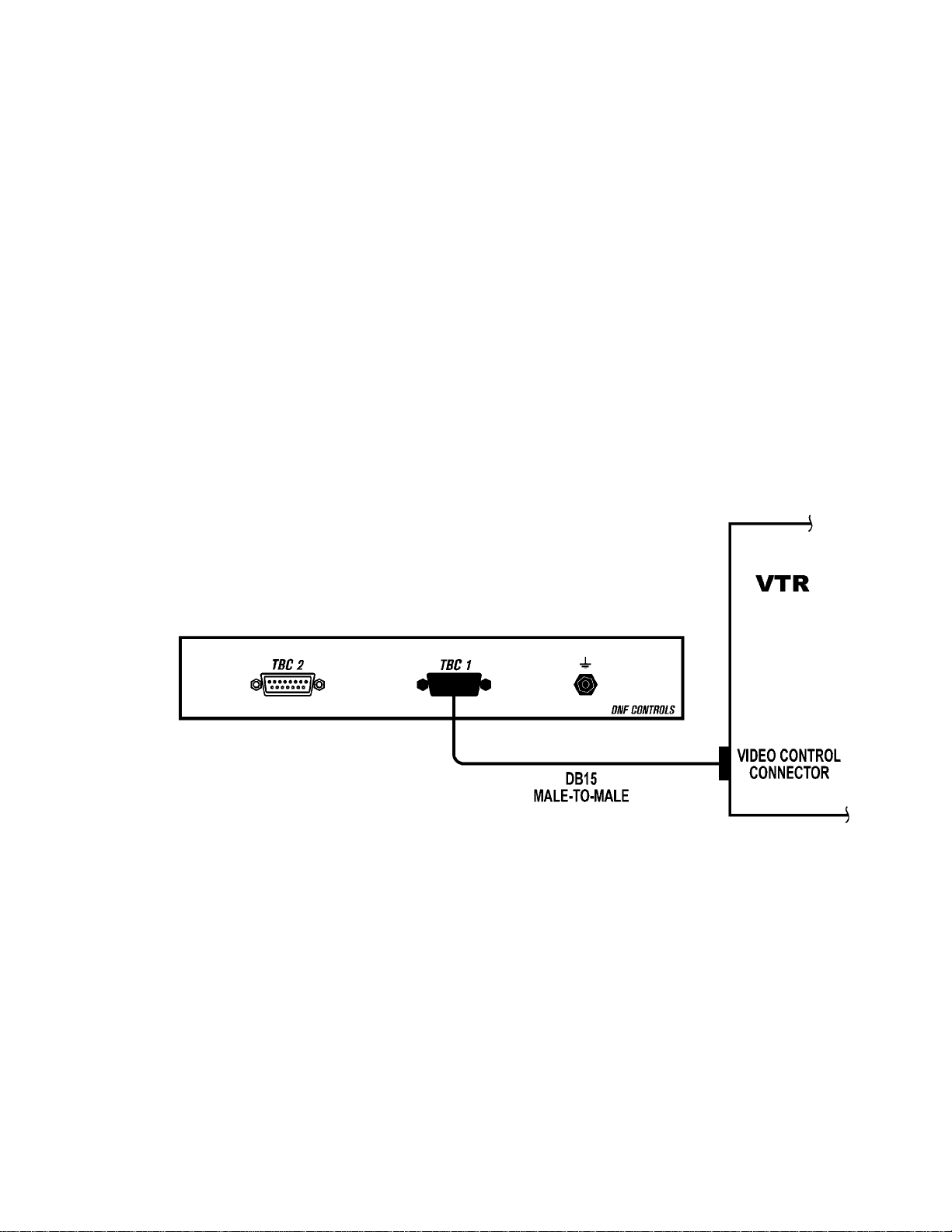
3. INSTALLATION
Connect one end of a D-sub15 cable to the TBC 2. Connect the other end of the cable to the
D-sub 15 on the VTR to be controlled. Identified as “Encoder Remote” or “Video Control.”
Because the TBC Remote connector has power on its pins, cabling should be done only with the
VTR power switch turned off. Once the TBC-2 panel is securely connected to the VTR, power
may be safely turned on.
Installation is Complete
CONNECTION DIAGRAM
4 TBC-2 DVC
Page 5

4. ADJUSTMENTS
Each control is clearly labeled for its function. Each control may be adjusted over a wide range.
Each control may be switched “in” or “out” by using the toggle switch located below the control.
The “out” position sets that function to unity gain (as set within the VTR). The “in” position
enables the associated control.
SetUp Adjust to eliminate any deviation
Video Gain Adjust to 100 IRE.
Chroma Gain Adjust so that the specified level is obtained.
Hue Adjust so that the vector waveform meets the VTR specifications.
a. H PHASE AND SUBCARRIER ADJUSTMENTS
These controls are inset screwdriver adjustments. These adjustments are best made
using a waveform/vectorscope and good video alignment practice by trained personnel
only. Consult the VTR operator/s or service manual for the correct procedure.
SC Fine and H Phase are “greenie” adjustment pots.
b. S/C COARSE
Monitor your vector scope and adjust the SC Coarse switch until you are “in the
ballpark,” then adjust the SC fine (slotted screwdriver adjustment) until you have
adjusted within the unit’s specifications.
0 = coarse 1 & 2 open
1 = coarse 1 to ground
2 = coarse 2 to ground
3 = coarse 1 & 2 to ground
5 TBC-2 DVC
Page 6

5. SPECIFICATIONS
2 TBC Controllers in 1 RU housing
Physical: L x W x H: 19” x 2-1/2” x 1- 3/4”
Weight: 2 lbs.
ADJUSTMENTS
a. FRONT PANEL CONTROL VIA KNOB
(All with individual bypass switch on front panel)
Video Gain Range: +/- 3dB (+/- 20 IRE)
Setup Range: +/- 15 IRE
C-Gain:
Hue Range: +/- 30 Degrees
b. FRONT PANEL CONTROL
(Via inset slotted screwdriver adjustment)
Subcarrier Phase: +/- 180 Degrees
(two adjustments, coarse and fine)
H Phase: +/- 15mSec
6 TBC-2 DVC
Page 7

7. DNF CONTROLS LIMITED WARRANTY
DNF Controls warrants its product to be free from defects in material and workmanship for a period of one
(1) year from the date of sale to the original purchaser from DNF Controls.
In order to enforce the rights under this warranty, the customer must first contact DNF’s Customer Support
Department to afford the opportunity of identifying and fixing the pr oblem without sending the unit in for
repair. If DNF’s Customer Support Department cannot fix the problem, the customer will be issued a
Returned Merchandise Authorization number (RMA). The customer will then ship the defective product
prepaid to DNF Controls with the RMA number clearly indicated on the customer’s shipping document.
The merchandise is to be shipped to:
DNF Controls
12843 Foothill Blvd., Suite C
Sylmar, CA 91342
USA
Failure to obtain a proper RMA number prior to returning the product may result in the return not being
accepted, or in a charge for the required repair.
DNF Controls, at its option, will repair or replace the defective unit. DNF Controls will return the unit
prepaid to the customer. The method of shipment is at the discretion of DNF Controls, principally UPS
Ground for shipments within the United States of America. Shipments to international customers will be
sent via air. Should a customer require the product to be returned in a more expeditious manner, the return
shipment will be billed to their freight account.
This warranty will be considered null and void if accident, misuse, abuse, improper line voltage, fire, water,
lightning or other acts of God damaged the product. All repair parts are to be supplied by DNF Controls,
either directly or through its authorized dealer network. Similarly, any repair work not performed by either
DNF Controls or its authorized dealer may void the warranty.
After the warranty period has expired, DNF Controls offers repair services at prices listed in the DNF
Controls Price List. DNF Controls reserves the right to refuse repair of any unit outside the warranty
period that is deemed non-repairable.
DNF Controls shall not be liable for direct, indirect, incidental, consequential or other types of damage
resulting from the use of the product.
# # #
7 TBC-2 DVC
 Loading...