

Page 1

12843 Foothill Blvd. Suite C
Sylmar, California 91342
V: 818.898.3380
F: 818.898.3360
sales@dnfcontrols.com
www.dnfcontrols.com
TALLY MANAGER Tally Control System
Getting Started Guide
Prior to configuring Tally Manager, assign and configure the control protocols on the
Device Controller channels. Refer to the DC20 Device Controller User Manual.
1. Create Tally Manager DC List ...................................................................................... 2
2. Backup and Restore the Tally Manager DC List Configuration File .......... 4
3. Configure Channel Mode in Protocol Assignment Table ................................ 6
4. Configure Router Inputs Table ................................................................................... 7
5. Configure Switcher Inputs Table............................................................................. 10
6. Configure Monitor Wall Inputs Table .................................................................... 12
7. Configure Camera Tallies Inputs Table ................................................................ 16
Page 1 of 16
Page 2

1. Create Tally Manager DC List
The Tally Manager DC List is used to define all of the Device Controllers (DC) used in your
Tally Manager system. This list is used on the Input Table configuration web pages, as a
“Source Device” drop down menu. It also is used to populate the Overview page on each
unit.
To create the Tally Manager DC List:
1) Click on the “System” link at the top of the page. A Log In prompt is displayed. Log
in using the DNF provided user name and password.
2) Click on the “Tally Manager DC List” link.
3) Click on the “Add” link at the top of the web page.
4) In the Device Name field, enter a name, maximum 32 characters in length, that
easily identifies the device being entered. This name is displayed in the “Source
Device” column drop down menu on all the Input configuration web pages.
Examples: “Area Router”, “PCR 1 Production Switcher”
5) In the Device Type field, select the type of device being entered from the pull-down
menu.
6) In the Description field, enter a description for the device being entered, maximum
100 characters. This description is displayed on the Tally Manager DC List web page,
and is only used for user information. It does not affect the operation of the system.
7) In the IP Address field, enter the IP address of the Device Controller connected to
the device identified by Device Name.
8) In the Control Channel field, enter the channel number that the device is connected
to on the DC20.
9) In the Backup Device field, enter the IP address of the backup DC that connects to
the same device as the primary. The same channel number on the primary and
backup DC must be connected to the device. If there is no backup IP address, do
not include this parameter.
10) In the Location Typefield , select whether this device is used Facility-wide or is used
within a single room. This will affect how the device is displayed in the Overview
page.
11) In the Location Name field, enter a descriptive name for where the device is located.
This location name will be displayed on the Overview page. This is used for user
information only, and does not affect the operation of the system. Examples: “PCR
21”,”2nd Floor Equipment Room”
12) Press the “Save” button to save the entered device. Or press the “Done” to return to
the previous page without saving the entered device.
Page 2 of 16
Page 3
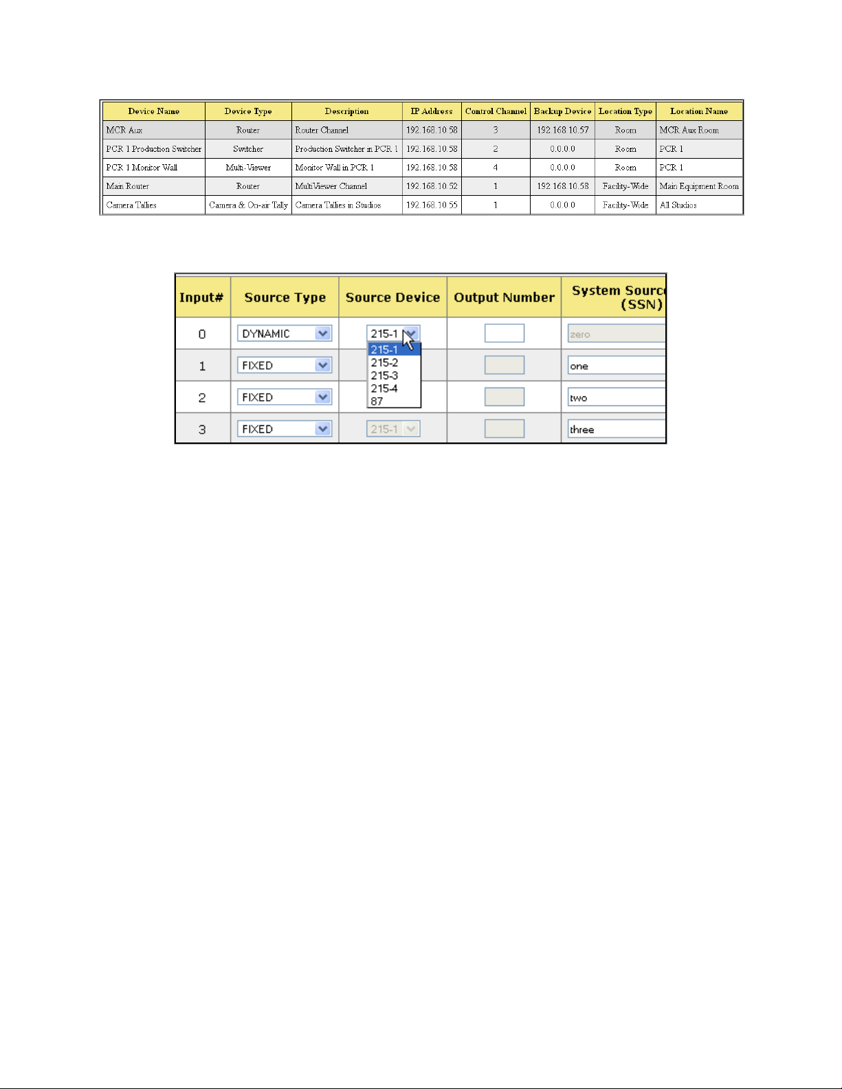
Resulting Source Device drop down menu on all Input Configuration web pages:
Page 3 of 16
Page 4
2. Backup and Restore the Tally Manager DC List Configuration
File
1) Launch your web browser and enter the Device Controller’s IP address. The DC’s
Home Page is displayed.
2) Click on the “System” link at the top of the page. A Log In prompt is displayed. Log
in using the DNF provided user name and password.
3) Click on the “Tally Manager DC List” link.
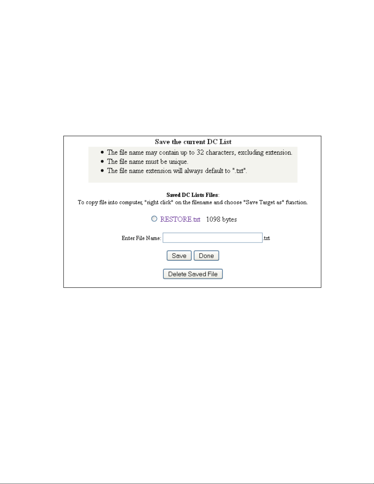
4) Click on the “Backup” link near at the top of the page.
5) Enter a file name for the backup file being created, then press the “Save” button.
The created backup file will be displayed after saving.
6) Right click on the created backup file, and press “Save Link As.” Save the file to your
PC.
If more Tally Manager Device Controllers need to be configured:
7) Launch your web browser and enter the Device Controller’s IP address. The DC’s
Home Page is displayed.
8) Click on the “System” link at the top of the page. A Log In prompt is displayed. Log
in using the DNF provided user name and password.
9) Click on the “Tally Manager DC List” link.
10) Click on the “Restore” link near at the top of the page.
Page 4 of 16
Page 5
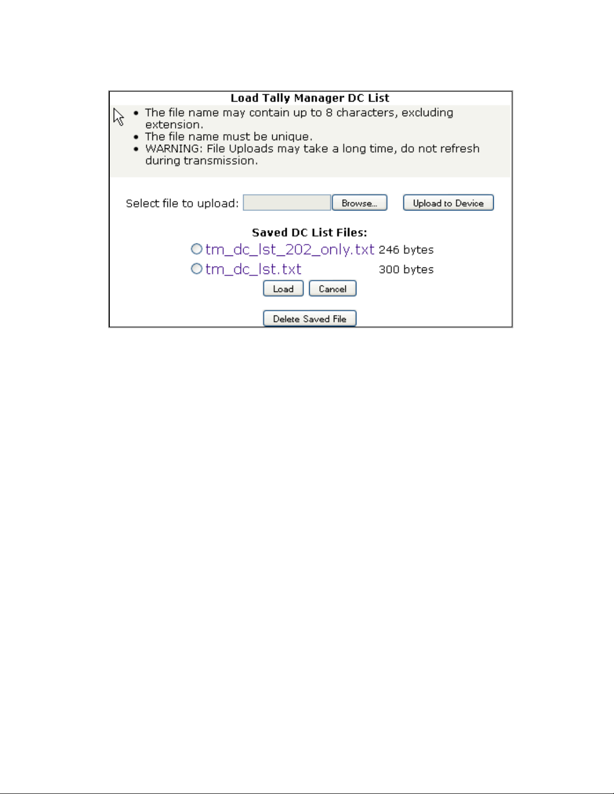
11) Click on the “Browse” button, and navigate to the folder where the backup file was
saved to on the PC. Double click on the backup file to select it.
12) Click on the “Upload to Device” button. NOTE: The file upload may take a few
seconds. Do not refresh the webpage while the upload is occurring. Once complete,
the webpage will refresh automatically.
13) Under “Saved DC List Files:” click on the radio button of the uploaded DC list.
14) Click on the “Load” button.
15) A confirmation prompt is displayed. Click on the “Load” button to load the file, or
click on “Cancel” to exit without loading the file.
16) Repeat for every Tally Manager Device Controller.
Page 5 of 16
Page 6

3. Configure Channel Mode in Protocol Assignment Table
1) Launch your web browser and enter the Device Controller’s IP address. The DC Home
Page is displayed.
2) Click on the “Protocol Assignment” link at the top of the page. The Protocol
Assignment Table is displayed.
3) On the Protocol Assignment Table, on the Channel 1 row, in the “Tally Manager
Config” column, click on the “Unassigned” link. The Channel Mode configuration web
page is displayed.
4) Click on the “Edit” link at the top of the web page.
5) Select the appropriate channel mode (device type) from the drop down menu that
describes the device connected to this DC channel. The available device types are
Router, Switcher, Monitor Wall, Camera Tallies and Router with DA. For example, if
a router is connected to Channel 1, select “Router”.
NOTE: If Router is selected, each router output can assigned to only one
production switcher or monitor wall Input. Select “Router with DA” to allow
a single router output to be assigned to multiple Inputs.
NOTE: Select “Camera Tallies” device type only on a channel with “Control
Protocol” set to “Unassigned“.
6) Click on the “SAVE MODE” button to save selection, or click on “BACK” button exit
without saving.
7) Click on the “Go Back” link to return to the Protocol Assignment Table web page. The
“Unassigned” link is replaced with the selected channel mode.
8) Repeat steps 3 through 7 for each Tally Manager channel.
Page 6 of 16
Page 7

4. Configure Router Inputs Table
1) Launch your web browser and enter the Device Controller’s IP address. The DC Home
Page is displayed.
2) Click on the “Protocol Assignment” link at the top of the page. The Protocol
Assignment Table is displayed.
3) On the Protocol Assignment Table, on the Router Channel row, in the “Tally Manager
Config” column, click on the “Inputs” link. The Router Inputs web page is displayed.
4) From the drop down menu displayed at the top of the Router Inputs web page, select
the range of Inputs to be configured.
Page 7 of 16
Page 8

5) Click the “Edit” link near the top of the Router Inputs web page.
6) For each Input, under the Source Type column, select “Unassigned”, “Fixed” or
“Dynamic.”
Fixed – Video source originates on this device.
Dynamic – Video source originates on another device.
NOTE: To set all Inputs to Fixed, press the “Set All to Fixed” button. This will affect
all Inputs on the router, not just those within the selected range.
7) If Fixed is selected, enter the System Source Name (SSN) for that Input, OR leave
the System Source Name field empty to use the System Source Name obtained from
the router. In the Alias column, select the Alias mode for that Input from the drop
down menu:
i. Disabled – No alias is allowed. Only the System Source Name will be
displayed on the UMD.
ii. Local – A local alias may be assigned to this Input on a monitor wall
that displays this Input. The alias will only affect the monitor wall
where it is configured.
iii. Global – A global alias may be assigned to this Input at the router. The
alias will affect all monitor walls that display this Input.
iv. Local Overrides Global – Local and global aliases may be assigned to
this Input. If a Local alias is assigned, it will override a Global alias
that has been assigned.
Page 8 of 16
Page 9

8) If Dynamic is selected, select the Source Device from the drop down menu and enter
the Output Number that the Input is connected to. If the Source Device is a router,
also enter the Level for that Output Number.
9) Repeat steps 6 through 8 for all Inputs as necessary.
10) Press the “SAVE_ALL” button to save the entered changes, or press the “Back”
button to return to the previous page and discard all entered changes.
Page 9 of 16
Page 10

5. Configure Switcher Inputs Table
1) Launch your web browser and enter the Device Controller’s IP address. The DC Home
Page is displayed.
2) Click on the “Protocol Assignment” link at the top of the page. The Protocol
Assignment Table is displayed.
3) On the Protocol Assignment Table, on the Switcher Channel row, in the “Tally
Manager Config” column, click on the “Inputs” link. The Switcher Inputs web page is
displayed.
4) From the drop down menu displayed at the top of the Switcher Inputs web page,
select the range of Inputs to be configured.
5) Click the “Edit” link near the top of the Router Inputs web page.
6) For each Input, under the Source Type column, select “Unassigned”, “Fixed” or
“Dynamic.” Typically, “Dynamic” is selected for switcher inputs.
Fixed – Video source originates on this device.
Dynamic – Video source originates on another device.
7) If Fixed is selected, enter the System Source Name (SSN) for that Input. In the Alias
column, select the Alias mode for that Input from the drop down menu.
i. Disabled – No alias is allowed. Only the System Source Name will be
displayed on the UMD.
ii. Local – A local alias may be assigned to this Input on a monitor wall
that displays this Input. The alias will only affect the monitor wall
where it is configured.
iii. Global – A global alias may be assigned to this Input at the router. The
alias will affect all monitor walls that display this Input.
iv. Local Overrides Global – Local and global aliases may be assigned to
this Input. If a Local alias is assigned, it will override a Global alias
that has been assigned.
Page 10 of 16
Page 11

8) If Dynamic is selected, select the Source Device from the drop down menu and enter
the Output Number that the Input is connected to. If the Source Device is a router,
also enter the Level for that Output Number.
9) Repeat steps 6 through 8 for all Inputs as necessary.
10) Press the “SAVE_ALL” button to save the entered changes, or press the “Back”
button to return to the previous page and discard all entered changes.
Page 11 of 16
Page 12

6. Configure Monitor Wall Inputs Table
A monitor wall may be made up of multiple multi-viewer cards, each individually
controlled over an Ethernet connection. Tally Manager “sees” all of the multi-viewer
cards as one control channel, on the Device Controller. In the Protocol Assignment
Table, in the PHY CFG column, select EDIT to enter the IP addresses for each of the
cards used.
Ethernet PHY Configuration
1. Enter a unique Card Label for each card. (TSL V5 protocol requires a separate entry
for each card output.)
2. Enter the card’s IP address.
3. Enter the card’s IP address. (Consult the card manufacturer’s documentation)
4. For TSL V5 protocol only, enter the screen number. (Consult the card manufacturer’s
documentation.)
Page 12 of 16
Page 13

Monitor Wall Inputs Table
UMD
Source Device
identifies the router or switcher output that feeds the
Left Tally
Source Device
ident
ifies the switcher or other device output that
Right Tally
Source Device
identifies the switcher or other device output that
Each UMD line in the Input Table has three (3) entries:
UMD input.
UMD# identifies the UMD on the monitor wall
(Primary)
(Secondary)
1) Launch your web browser and enter the Device Controller’s IP address. The DC Home
Page is displayed.
2) Click on the “Protocol Assignment” link at the top of the page. The Protocol
Assignment Table is displayed.
3) On the Protocol Assignment Table, on the Monitor Wall Channel row, in the “Tally
Manager Config” column, click on the “Inputs” link. The Monitor Wall Inputs web
page is displayed.
indicates that the UMD source is on-air, in-record, or in-use. When this
tally is “ON”, the UMD text is red.
Left Tally# identifies the controlled tally object on the monitor wall.
indicates that the UMD source is in-record or in-use.
Right Tally# identifies the controlled tally object on the monitor wall.
4) From the drop down menu displayed at the top of the Monitor Wall Inputs web page,
select the range of Inputs to be configured.
5) Click the “Edit” link near the top of the Router Inputs web page.
Page 13 of 16
Page 14

6) Select the multi-viewer card for the UMD identified in the UMD column. The Card
Label column is only displayed for Multi-viewers using an Ethernet protocol.
7) Enter the UMD ID number in the UMD column.
8) Select Source Type from the drop down menu in the Source Type column. Typically,
“Dynamic” is selected for monitor wall inputs.
Fixed – Source originates on this device.
Dynamic – Source originates on another device.
9) Select the Source Device for the Dynamic Input from the Source Device drop down
menu and its Output Number. If the Source Device is a router, also enter the Output
Level number.
Page 14 of 16
Page 15

10) In the Prefix Selection column, select the Prefix configuration that will be used on
that UMD.
ii. None – No Prefix will be displayed.
iii. Fixed – A fixed text will be displayed in front of the System Source
Name (SSN) or Alias.
iv. Alias – The Alias will be displayed in front of the System Source Name
(SSN).
v. SSN – The System Source Name (SSN) will be displayed in front of the
Alias.
11) If Fixed Prefix is selected, enter the fixed text in the Prefix column.
12) Repeat steps 6 through 11 for all monitor wall inputs.
13) Press the “SAVE_ALL” button to save the entered changes, or press the “Back”
button to return to the previous page and discard all changes.
Page 15 of 16
Page 16

7. Configure Camera Tallies Inputs Table
1) Launch your web browser and enter the Device Controller’s IP address. The DC Home
Page is displayed.
2) Click on the “Protocol Assignment” link at the top of the page. The Protocol
Assignment Table is displayed.
3) On the Protocol Assignment Table, on the Camera Tally Channel row, in the “Tally
Manager Config” column, click on the “Inputs” link. The Camera Tally Inputs web
page is displayed.
4) Click the “Edit” link near the top of the Camera Tally Inputs web page.
5) For each GPO or Virtual Tally, assign a video signal System Source Name. When
that SSN appears on the output of the selected Source Device, the GPO or Virtual
Tally turns on.
6) Select the Source Device from the drop down menu and enter the Output Number
that will be monitored. If the Source Device is a router, also enter the Level for that
Output Number.
7) Repeat steps 5 – 6 for each GPO and Virtual Tally that will be used.
8) Press the “SAVE_ALL” button to save the entered changes, or press the “Back”
button to return to the previous page and discard all entered changes.
Page 16 of 16
 Loading...