

Page 1

12843 Foothill Blvd. Suite C
Sylmar, California 91342
V: 818.898.3380
F: 818.898.3360
sales@dnfcontrols.com
Model No. SW2X1
-GPI SWITCHER
-RS422 SWITCHER
USER MANUAL
Rev. 1.2
For Use with Rev 2.0 Hardware
SW2X1 User Manual 1 of 15
Page 2

Table of Contents
1. STANDARD FEATURES 4
2. INSTALLATION SW2X1-GPI 4
3. CONNECTION DIAGRAM SW2X1-GPI 5
4. INSTALLATION SW2X1-RS422 6
5. CONNECTION DIAGRAM SW2X1-RS422 6
6. MODE SELECTION SW2X1-GPI 7
a. MODE 1 7
b. MODE 2 7
7. MODE SELECTION SW2X1-RS422
(LOCAL / REMOTE CONTROL) 8
a. MODE 1 8
b. MODE 2 8
8. MODE SELECTION SW2X1-RS422 (2X1 / 1X2 MODE) 9
a. MODE 1 9
b. MODE 2 9
9. WIRING EXAMPLE 10
10. SPECIFICATIONS 11
A. OVERALL 11
B. SW2X1-GPI 12
C. SW2X1-RS422 12
11. FRONT / REAR VIEW 13
a. FRONT VIEW: SW2X1-GPI 13
DNF CONTROLS LIMITED WARRANTY 14
SW2X1 User Manual 2 of 15
Page 3

REVISION HISTORY
072707 Rev. 1.00 Original manual
081707 Rev. 1.01 Added GPI wet-dry jumper description.
102411 Rev. 1.1 Added 1x2 mode for SW2X1-RS422
082312 Rev 1.2 Added polarity indicators to RS422 pin outs
061113 Rev 1.3 Revised wet and dry jumper configuration for SW2x1
GPI
SW2X1 User Manual 3 of 15
Page 4
1. STANDARD FEATURES
The SW2X1, Electronic A / B switch has 2 buffered inputs and one
buffered output for easy interfacing. There are no mechanical multi-pole
switches to wear out or fail.
Front panel control and remote control provide flexible operation to fit
your specific application.
Quickly and easily switch from primary system to backup system at the
press of a button.
In the event of power failure, on-board bypass relays switches “A” input to
output.
2. INSTALLATION SW2X1-GPI
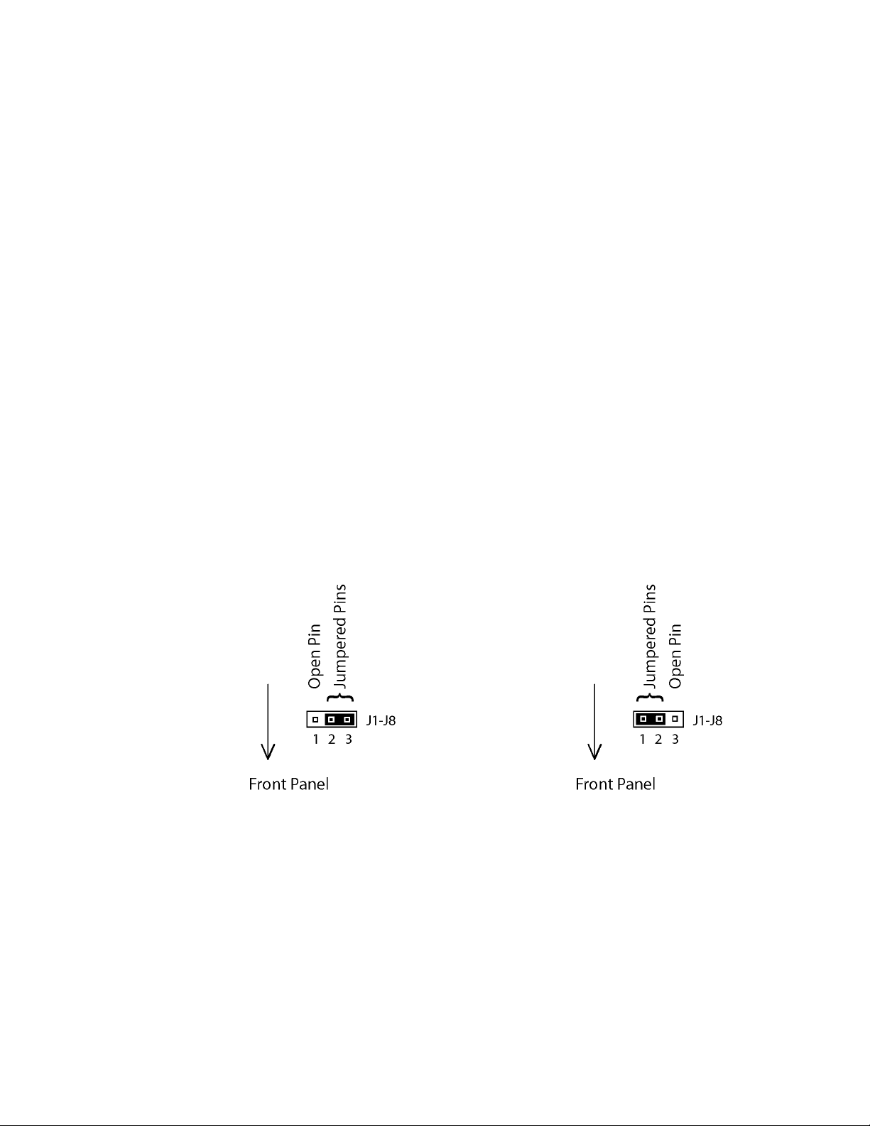
a. Chose whether the GPI will be self powered or have power supplied by
the source equipment. Each GPI is independently settable.
JUMPERS: J1 – J8
Revision 08/16/07
DRY: External circuit powers
INPUT opto-isolator
INPUT is isolated from other inputs
Place jumper over pins 2 and 3
WET: SW2X1 powers INPUT optoisolator
External circuit provides path to
ground
Place jumper over pins 1 and 2
SW2X1 User Manual 4 of 15
Page 5
b. Connect primary GPO source to the A input connector, use male D9
cable connector.
c. connect secondary GPO source to the B input connector, use male D9
cable connector.
d. Connect the destination GPI connections to the Output connector.
e. Connect the power supply’s connector (9-pin female D) into the
housing’s POWER connector (male 9-pin D). The PWR LED on front
panel will light. Power supply is +5VDC. 2A.
f. NOTE: The Power-up state defaults to input A and its status indicator
will light.
Installation is complete.
3. CONNECTION DIAGRAM SW2X1-GPI
SW2X1 User Manual 5 of 15
Page 6

4. INSTALLATION SW2X1-RS422
a. Connect one end of an RS422 cable (9-pin D-type, male to male, 1 to 1)
into the rear panel connector (9-pin D-type) labeled INPUT A. Connect
the other end to an RS422 serial source (controller #1).
b. Connect a second RS422 serial source (controller #2) in the same
manner to INPUT B.
c. Connect an RS422 serially controlled VTR, (using an RS422, 9-pin D-
type male to male cable) into the 9-pin female connector labeled
OUTPUT.
d. Connect the power supply’s connector (9-pin female D) into the
housing’s POWER connector (male 9-pin D). The PWR LED on front
panel will light. Power supply is +5VDC. 2A.
e. NOTE: The Power-up state defaults to input A and its status indicator
will light.
Installation is complete.
5. CONNECTION DIAGRAM SW2X1-RS422
SW2X1 User Manual 6 of 15
Page 7

6. MODE SELECTION SW2X1-GPI
The SW2X1-GPI supports two modes of operation.
a. MODE 1
Remote and local control is possible.
Active A input or A switch = Select A input.
Active B input or B switch = Select B input.
This is the default mode. The jumper is installed
over pins 3 and 4 on header J11 on the PCB.
The mode of operation is determined ONLY at
POWER UP. Changing the jumper after power up
will have no effect. Power MUST be turned off then
on to change the SW2X1’s MODE.
Jumper Diagram for Mode 1.
b. MODE 2
Remote control ONLY is possible. Local control is
disabled.
The LOCKOUT LED is turned on.
Remote B input inactive = Select A input.
Remote B input active = Select B input.
The jumper is installed over pins 1 and 2 on
header J11 on the PCB.
The mode of operation is determined ONLY at
POWER UP. Changing the jumper after power up
will have no effect. Power MUST be turned off
then on to change the SW2X1’s MODE.
Jumper Diagram for Mode 2.
SW2X1 User Manual 7 of 15
Page 8

7. MODE SELECTION SW2X1-RS422 (LOCAL /
REMOTE CONTROL)
The SW2X1-RS422 supports two modes of control.
a. MODE 1
Remote and local control is possible.
Active A input or A switch = Select A input.
Active B input or B switch = Select B input.
This is the default mode. A jumper is installed over pins 3 and 4 on
the J1 header on the PCB.
The mode of operation is determined ONLY at POWER UP. Changing
the jumper after power up will have no effect. Power MUST be turned
off then on to change the SW2X1’s MODE.
Jumper Diagram for Mode 1.
b. MODE 2
Remote control ONLY is possible. Local control is disabled.
The LOCKOUT LED is turned on.
Remote B input inactive = Select A input.
Remote B input active = Select B input.
A jumper is installed over pins 1 and 2 on the J1 header on the PCB.
The mode of operation is determined ONLY at POWER UP. Changing
the jumper after power up will have no effect. Power MUST be turned
off then on to change the SW2X1’s MODE.
Jumper Diagram for Mode 2.
SW2X1 User Manual 8 of 15
Page 9

8. MODE SELECTION SW2X1-RS422 (2X1 /
1X2 MODE)
The SW2X1-RS422 supports two modes of operation.
a. MODE 1
The unit operates in 2 in / 1 out mode.
This is the default mode. A jumper is installed over pins 1 and 2 on the
J3 header on the PCB.
The mode of operation is determined ONLY at POWER UP. Changing
the jumper after power up will have no effect. Power MUST be turned
off then on to change the SW2X1’s MODE.
Jumper Diagram for Mode 1
b. MODE 2
The unit operates in 1 in / 2 out mode.
A jumper is installed over pins 2 and 3 on the J3 header on the PCB.
The mode of operation is determined ONLY at POWER UP. Changing
the jumper after power up will have no effect. Power MUST be turned
off then on to change the SW2X1’s MODE.
Jumper Diagram for Mode 2
SW2X1 User Manual 9 of 15
Page 10

OPERATION
a. To use the front panel controls, ensure that LOCKOUT switch on front
panel is set to the right side. LOCKOUT LED will not illuminate.
b. To select a source, press the red ENABLE switch simultaneously with
a black SELECT switch, A or B. The selected input's status indicator
will light.
c. Setting the LOCKOUT switch to ON (to the left side) will disable the
front panel ENABLE and SELECT switches. The LOCKOUT LED will
illuminate. In LOCKOUT, the SW2X1 can only be controlled via the
EXTERNAL SELECT connector on the rear panel.
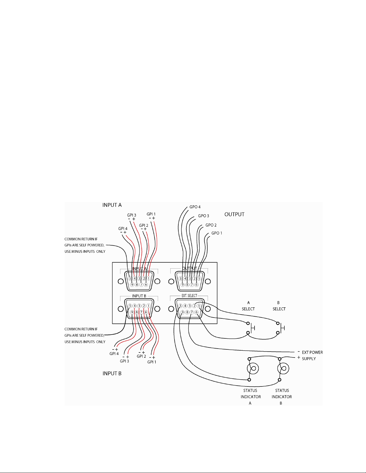
9. WIRING EXAMPLE
SW2X1 User Manual 10 of 15
Page 11

10. SPECIFICATIONS
A. OVERALL
Power: 90 VAC to 265 VAC adapter supplied with IEC connector
Size: (H” x W” x D”) 1.75” x 19” x 4.25”
Weight: 6 lbs.
Rear Panel Connectors: INPUT A, INPUT B (D9F)
OUTPUT, EXT. SELECT (D9F)
Power (D9M)
Ground #6-32 threaded stud
Front Panel Controls: Enable, Select A, Select B (All pushbutton
switches).
Lockout ON/OFF (Recessed slide
switch).
Front Panel Indicators: Power, Lockout On, A, B. All red LEDs.
EXTERNAL SELECT CONNECTOR
9-Pin D-Type Female (D9F)
Pin # Description
1 External select A (Active low, opto-isolated internally)
2 External select B (Active low, opto-isolated internally)
3 n/c
4 n/c
5 LED B (external) drive, B input status indicator
6 GROUND
7 GROUND
8 n/c
9 LED A (external) drive, A input status indicator
NOTE:
There are no internal current limiting resistors for the open collector status
indicator drives. A 470 ohm resistor in series with a + 5 Vdc power supply is
recommended.
Limit lamp current to 50mA MAXIMUM.
POWER CONNECTOR
9-Pin D-Type Male, (D9M)
PIN# Description PIN# Description
1 +5 Vdc 6 +5 Vdc
2 +5 Vdc 7 Ground
3 Ground 8 Ground
4 n/c 9 Ground
5 n/c
MODULE: P1 (2 PIN MOLEX)
Pin# Description
1 +5VDC (left on P1, near card edge)
2 GND (right on P1)
SW2X1 User Manual 11 of 15
Page 12

B. SW2X1-GPI
GPI INPUT CONNECTOR
9-Pin D-Type Female (D9F)
Pin# Description Pin# Description
1. GPI 1 + (A) or internal pull-up 6. GPI 1 - (K)
2. GPI 2 + (A) or internal pull-up 7. GPI 2 - (K)
3. GPI 3 + (A) or internal pull-up 8. GPI 3 - (K)
4. GPI 4 + (A) or internal pull-up 9. GPI 4 - (K)
5. Ground
Note: Internal pull-up is jumper selectable for each GPI, then only a
connection from the 'K' pin to ground is required for GPI activation.
GPI OUTPUT CONNECTOR
9-Pin D-Type Female (D9F)
Pin# Description Pin# Description
1. GPO 1 N.O. 6. GPO 1 COM
2. GPO 2 N.O. 7. GPO 2 COM
3. GPO 3 N.O. 8. GPO 3 COM
4. GPO 4 N.O. 9. GPO 4 COM
5. Ground
C. SW2X1-RS422
RS422 SERIAL INPUT (Device Configuration)
9-Pin D-Type Female (D9F)
Pin# Description
1 Frame Ground
2 Transmit A(-)
3 Receive B(+)
4 Transmit common
5 Spare
6 Receive common
7 Transmit B(+)
8 Receive A(-)
9 Frame Ground
RS422 SERIAL OUTPUT (Controller Configuration)
9-Pin D-Type Female (D9F)
Pin# Description
1 Frame Ground
2 Receive A(-)
3 Transmit B(+)
4 Transmit common
5 Spare
6 Receive common
7 Receive B(+)
8 Transmit A(-)
9 Frame Ground
SW2X1 User Manual 12 of 15
Page 13

11. FRONT / REAR VIEW
a. FRONT VIEW: SW2X1-GPI
b. FRONT VIEW: SW2X1-RS422
c. REAR VIEW: SW2X1
SW2X1 User Manual 13 of 15
Page 14

DNF CONTROLS LIMITED WARRANTY
DNF Controls warrants its product to be free from defects in material and
workmanship for a period of one (1) year from the date of sale to the original
purchaser from DNF Controls.
In order to enforce the rights under this warranty, the customer must first contact
DNF’s Customer Support Department to afford the opportunity of identifying and
fixing the problem without sending the unit in for repair. If DNF’s Customer Support
Department cannot fix the problem, the customer will be issued a Returned
Merchandise Authorization number (RMA). The customer will then ship the defective
product prepaid to DNF Controls with the RMA number clearly indicated on the
customer’s shipping document. The merchandise is to be shipped to:
DNF Controls
12843 Foothill Blvd., Suite C
Sylmar, CA 91342
USA
Failure to obtain a proper RMA number prior to returning the product may result in
the return not being accepted, or in a charge for the required repair.
DNF Controls, at its option, will repair or replace the defective unit. DNF Controls will
return the unit prepaid to the customer. The method of shipment is at the discretion
of DNF Controls, principally UPS Ground for shipments within the United States of
America. Shipments to international customers will be sent via air. Should a
customer require the product to be returned in a more expeditious manner, the
return shipment will be billed to their freight account.
This warranty will be considered null and void if accident, misuse, abuse, improper
line voltage, fire, water, lightning, or other acts of God damaged the product. All
repair parts are to be supplied by DNF Controls, either directly or through its
authorized dealer network. Similarly, any repair work not performed by either DNF
Controls or its authorized dealer may void the warranty.
After the warranty period has expired, DNF Controls offers repair services.
Equipment is evaluated and repair price quoted prior to any work performed. DNF
Controls reserves the right to refuse repair of any unit outside the warranty period
that is deemed non-repairable.
DNF Controls shall not be liable for direct, indirect, incidental, consequential or other
types of damage resulting from the use of the product.
# # #
SW2X1 User Manual 14 of 15
 Loading...