

Page 1

12843 Foothill Blvd.,
Suite D
Sylmar, CA 91342
818 898 3380 voice
818 898 3360 fax
www.dnfcontrols.com
ST60-DVC
VTR CONTROLLER
ST60-AG57
VTR CONTROLLER
USER MANUAL
Manual Version ………..………………….. 2.1 122203
Document ID: …………. ST60-DVC_User_Manual.doc
1
ST60-DVCPRO
Page 2

1. REVISION HISTORY
122203 Rev. 2.1 Company header information revised.
Added DNF Controls Limited Warranty.
2
ST60-DVCPRO
Page 3

THE ST60-DVC VTR CONTROLLER
The ST60-DVC VTR Controller is ideal for Television Stations, Cable TV, Video
Production, Video Post-production, Audio Post-production, Duplication Houses and
Corporate Video Facilities.
STANDARD FUNCTIONS
RECORD REWIND
PLAY FAST FORWARD
STOP EJECT
REAL-TIME STATUS INDICATORS (ACTIVE ON)
RECORD REWIND/REVERSE
PLAY FAST FORWARD/FORWARD
STOP/STILL
2. INSTALLATION
a. Set the VTR's Data transfer rate to 9600 baud, No Parity, 8 bits, 1 stop bit.
Set ACK RETURN to off. See the DVCPRO User’s Manual.
b. Plug the 9-pin connector end of an RS232 serial cable in to the 9-pin
female connector on the rear of the ST60. Plug the 25-pin connector end
of the same cable into the 25-pin female “RS232-C” remote connector on
the rear of the VTR. See wiring information below.
c. Plug the POWER SUPPLY’s 9-pin connector into the 9-pin male
connector “POWER” on the rear of the ST60. Plug the other end of the
POWER SUPPLY into 90 VAC to 265 VAC.
d. Select REMOTE operation on the VTR's front panel.
e. Set the RECORD SELECTOR SWITCHES, located on the rear panel of
the S60, to the desired record mode per the "RECORD SELECTOR
CHART."
f. Set Dip Switch #6, on the rear panel, as follows:
ON AJ-D230, AG-5710
OFF AJ-D750, AJ-D640, & all others
3
Installation is completed.
ST60-DVCPRO
Page 4

3. OPERATION
Select the desired transport function by pressing the appropriate switch on the front of the
ST60.
The Real-Time Status Indicators will light to indicate the VTR's current tape transport
mode.
For example - Pressing [PLAY] will put the VTR into the PLAY mode.
PLAY Status Indicator will light when the VTR is in PLAY mode.
The real-time Tape Counter is displayed on the LCD Display.
Loss of serial communication with the VTR is indicated by ALL Status LEDs turned ON.
4. RECORD MODE
Two (2) Record modes are available: Crash Record (Full Record), and Record Lockout.
Press only the [RECORD] switch to activate the selected Record mode.
The Record Status Indicator will turn on when the VTR begins recording.
NOTE: The VTR will not go into Record mode if "Record Inhibit" is enabled on the
VTR or tape cassette.
5. RECORD SELECTOR SWITCHES
Mode S1 S2 S3 S4 S5 S6
Record Lockout OFF OFF OFF OFF OFF OFF
Full Record OFF ON OFF OFF OFF OFF
4
ST60-DVCPRO
Page 5
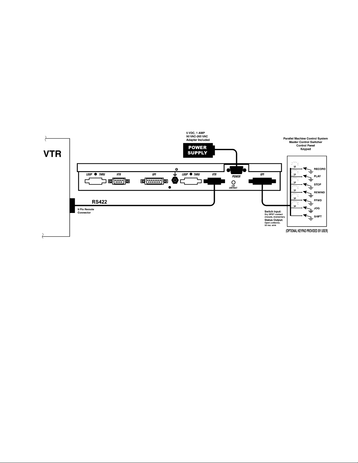
Connection Diagram
5
ST60-DVCPRO
Page 6

6. SPECIFICATIONS
Front Panel:
6-Status LEDs Record, Play, Stop, Rewind, Fast Forward
1 Power LED
Size 7” x 5” x 1-1/2”, female
Weight 2 lbs.
Rear Panel:
RS 422 Serial Output 9-Pin D-type connector, female (DB9F)
Power 9VDC, 500 mA, 100-265 VAC 50/60 Hz.
Record Selector 6-pole dip switch
Keypad Interface: 15-Pin D-type connector, Female (DB15F)
Switch Input - dry SPST momentary contact closure.
POWER SUPPLY CONNECTOR
9-Pin D-Type, Male (DB9M)
Pin# 1 +5Vdc Pin# 6 +5Vdc
2 +5Vdc 7 Ground
3 Ground 8 Ground
4 9 Ground
5
6
ST60-DVCPRO
Page 7

ST60 GPI In/Out C
15-Pin D-Type, Female (DB15F)
PIN FUNCTION
1 +5v DC
2 SHIFT Switch, Active Low
3 Record Tally Actvie Low, Open-Collector
4 Play Tally Actvie Low, Open-Collector
5 Stop/Still Tally Actvie Low, Open-Collector
6 Rewind/ Reverse Tally Actvie Low, Open-Collector
7 Fast Forward/ Forward Tally Actvie Low, Open-Collector
8 No Connection
9 Command Common
10 Record Command Active Low
11 Play Command Active Low
12 Stop Command Active Low
13 Rewind Command Active Low
14 Fast Forward Command Active Low
15 No Connection
NOTE: There are no internal current limiting resistors for the open- collector, status
indicator drives. A 62-ohm resistor in series with the +9 volt D.C. power supply is
recommended for LEDs. Limit lamp current to 50 ma. at 9 volts D.C.
ONNECTOR
VTR Connector, RS232 Serial Interface
9-Pin D-Type, Female (DB9F)
Pin # 1 Not Used
2 Receive Data
3 Transmit Data
4 Not Used
5 Ground
6 Not Used
7 Not Used
8 Not Used
9 Not Used
7
ST60-DVCPRO
Page 8

DVCPRO VTR
25-Pin D-Type, Female (DB25F)
1 Not Used
2 Receive Data
3 Transmit Data
4 Not Used
5 Ground
6 Not Used
7 Signal Ground
8-25 Not Used
AG5710 VTR
25-Pin D-Type, Female (DB25F)
1 Not Used
2 Receive Data
3 Transmit Data
4RTS
5CTS
6DTR
7 Signal Ground
8 Not Used
9 Not Used
10 Not Used
11 Not Used
12 Not Used
13 Not Used
14 Not Used
15 Not Used
16 Not Used
17 Not Used
18 Not Used
19 Not Used
20 DSR
21 Not Used
22 Not Used
23 Not Used
24 Not Used
25 Not Used
You must wire the 25-pin connector at the VTR as follows:
Jumper Pins 4 and 5 together.
Jumper Pins 6 and 20 together.
8
ST60-DVCPRO
Page 9

7. DNF CONTROLS LIMITED WARRANTY
DNF Controls warrants its product to be free from defects in material and workmanship
for a period of one (1) year from the date of sale to the original purchaser from DNF
Controls.
In order to enforce the rights under this warranty, the customer must first contact DNF’s
Customer Support Department to afford the opportunity of identifying and fixing the
problem without sending the unit in for repair. If DNF’s Customer Support Department
cannot fix the problem, the customer will be issued a Returned Merchandise
Authorization number (RMA). The customer will then ship the defective product prepaid
to DNF Controls with the RMA number clearly indicated on the customer’s shipping
document. The merchandise is to be shipped to:
DNF Controls
12843 Foothill Blvd., Suite D
Sylmar, CA 91342
USA
Failure to obtain a proper RMA number prior to returning the product may result in the
return not being accepted, or in a charge for the required repair.
DNF Controls, at its option, will repair or replace the defective unit. DNF Controls will
return the unit prepaid to the customer. The method of shipment is at the discretion of
DNF Controls, principally UPS Ground for shipments within the United States of
America. Shipments to international customers will be sent via air. Should a customer
require the product to be returned in a more expeditious manner, the return shipment will
be billed to their freight account.
This warranty will be considered null and void if accident, misuse, abuse, improper line
voltage, fire, water, lightning or other acts of God damaged the product. All repair parts
are to be supplied by DNF Controls, either directly or through its authorized dealer
network. Similarly, any repair work not performed by either DNF Controls or its
authorized dealer may void the warranty.
After the warranty period has expired, DNF Controls offers repair services at prices listed
in the DNF Controls Price List. DNF Controls reserves the right to refuse repair of any
unit outside the warranty period that is deemed non-repairable.
DNF Controls shall not be liable for direct, indirect, incidental, consequential or other
types of damage resulting from the use of the product.
# # #
9
ST60-DVCPRO
 Loading...