

Page 1

12843 Foothill Blvd. Suite C
Sylmar, California 91342
V: 818.898.3380
F: 818.898.3360
sales@dnfcontrols.com
Model No. DMAT-MAV
USER MANUAL
DDMMAATT--MMAAVV
11
Page 2

Table of Contents
SECTION CONTENTS PAGE
1. REVISION HISTORY ………………………….. 3
2. DESCRIPTION....................................................... 3
Getting Started . . .
3. INSTALLATION................................................... 5
4. GETTING STARTED…………………………… 7
5. SETUP MENU....................................................... 9
A. Record.......................................................... 10
B. Set & Clear................................................... 11
6. OPERATIONS....................................................... 20
A. Creating a Playlist....................................... 21
B. Effects ........................................................... 23
Reference . . .
7. FUNCTION TABLE............................................. 25
8. SPECIFICATIONS............................................... 26
9. KEY LAYOUT ………………………………….. 28
10. DNF CONTROLS LIMITED WARRANTY ….. 29
Manual Version:.................................................4.3 120103
Document ID:.............................DMAT-MAV_ User_Manual
DDMMAATT--MMAAVV
22
Page 3
1. REVISION HISTORY
120103 Rev. 4.3 Company header information revised.
Added DNF Controls Limited Warranty.
2. DESCRIPTION
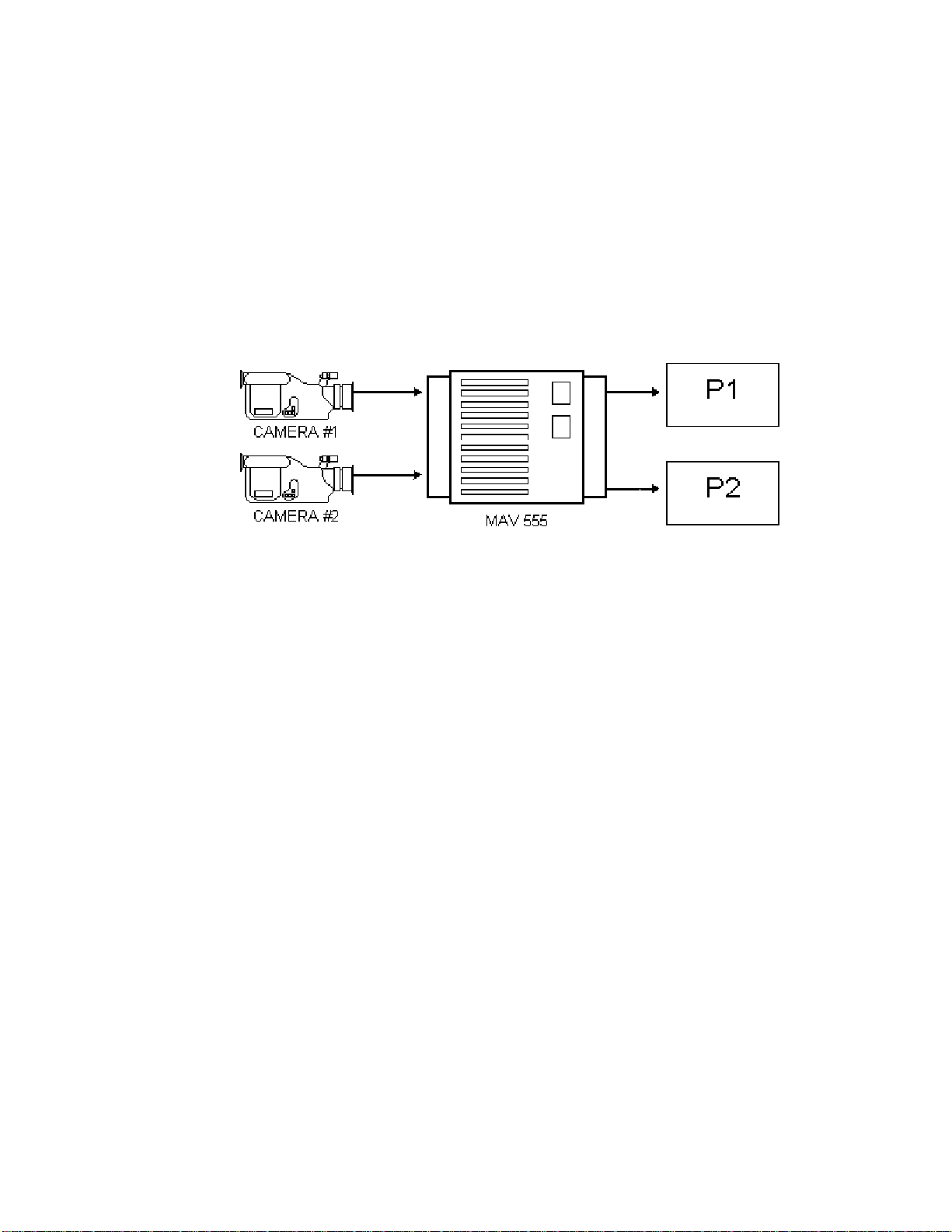
A. 2PGM MODE OVERVIEW
The system preferred by operators working in sports production all over America. With
continuous record and independent control of both playback channels, you’ll never miss a thing!
Figure1A
DDMMAATT--MMAAVV
33
Page 4
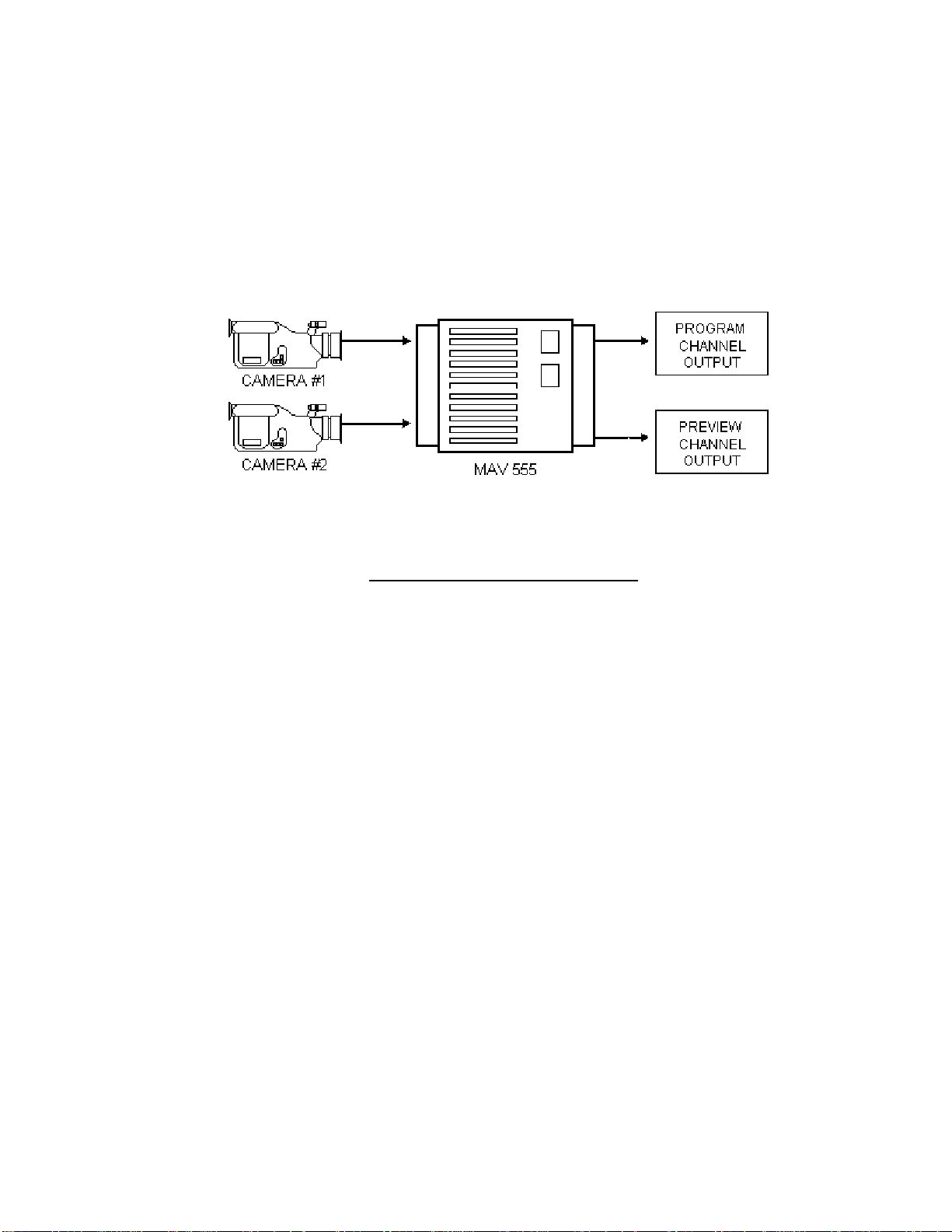
B. PROGRAM & PREVIEW MODE OVERVIEW
The two MAV output channels gives two views into the recorded material, a PREVIEW view and
a PROGRAM view. The PROGRAM output is the AIR feed. Only the [PLAY] and T-Bar
SLOMO functions control this output; all other transport functions control the PREVIEW output.
The PREVIEW output is used to view marked Cue Points, view clips or playback a camera feed to
find the desired video.
To switch video to the PROGRAM channel from the PREVIEW channel, the [CUT], [MIX] and
[WIPE] functions are used. The duration of the MIX and the pattern and duration of the WIPE are
definable by pressing [EDIT EFFECT].
Figure1B
The GANG mode means that all transport functions apply to both Program and Preview channels,
e.g., press [PLAY] to put both channels in PLAY, move the T-Bar to slomo both channels, press
[STOP] to stop both channels, press [REC] to put both channels into EE mode.
Primary operating modes are:
PLAYBACK Press [PLAY]
EE Mode Press [REC]
CLIP PLAY Mode Press [RECALL CLIP]
LIST PLAY Mode Press [CUE LIST]
FEATURES:
9 8 Cue Points
9 400 Clips
9 12 Play Lists
9 30 Clips/List
9 1 or 2 Camera Operation
DEFINITIONS
Throughout this document, the SONY MAV-555 will be referred to as MAV, MAV-555 or “Video
Server”.
Words surrounded by brackets in bold type, for example, [ENTER], are labeled keys on the ST400.
Words surrounded by brackets in bold italic type, for example, [CLIP], are multi-function SOFTKEYS
[XXX] + [XXX] means hold the two keys down simultaneously.
CP mode is CLIP Play; PL mode is LIST Play
DDMMAATT--MMAAVV
44
Page 5

3. INSTALLATION
(For 2 in/2 out configuration – both PGM & PVW and 2PGM)
1. Plug one end of a 9-conductor RS422 serial cable into the VTR1 connector on the rear of
2. In a similar manner, connector VTR2 to P2; VTR4 to R1; VTR 5 to R2.
(For 1 PGM configuration for HD MAVs)
2. Plug the POWER SUPPLY into a wall outlet, 90 VAC TO 240 VAC.
3. Select REMOTE mode on the MAV's front panel.
1. Connect VTR1 connector on the back of the DMAT to the P2 on the MAV.
2. Connect VTR4 connector on the back of the DMAT to the R2 connector on the MAV.
(For use as a Super Slo-mo unit)
1. Connect VTR1 connector on the back of the DMAT to the P2 on the MAV.
2. Connect VTR4 connector on the back of the DMAT to the R1 connector on the MAV.
(For all configurations)
1. Plug the DB9M connector from the supplied power supply into the power connector on
the DMAT-MAV controller.
Plug the other end of the cable into the connector labeled P1 on the rear panel of the
MAV.
the rear panel of the ST400.
DO NOT HOT PLUG! Always connect the power supply to the ST400
BEFORE
connecting to AC power
DDMMAATT--MMAAVV
55
Page 6
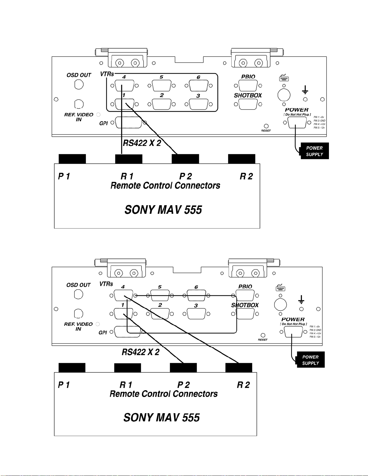
Super Slo-mo Connection Diagram
Figure 2A
1 PROGRAM Connection Diagram
Figure 2B
DDMMAATT--MMAAVV
66
Page 7
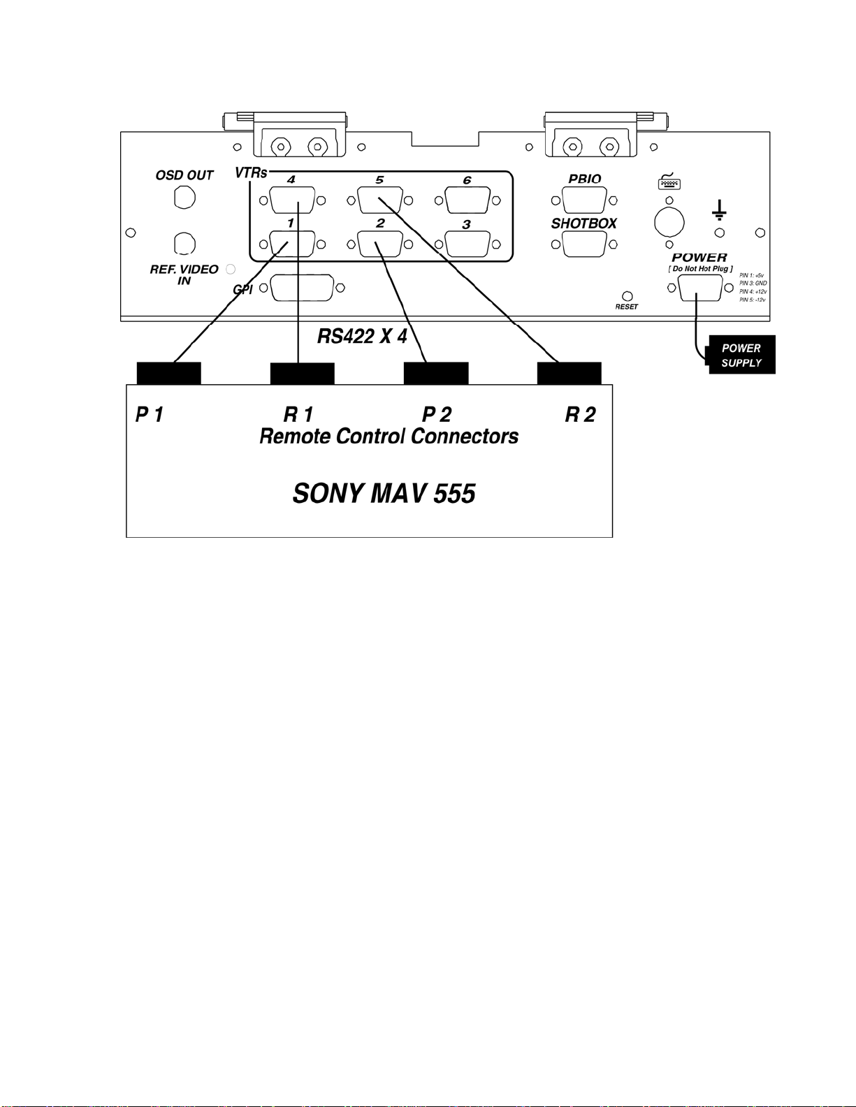
2 PGM and PGM & PVW Connection Diagram
Figure 2C
4. GETTING STARTED…
TART RECORDING
S
1. Press [MENU].
2. Press [RECORD SETUP].
3. Press [NEW R1 CLIP] or [NEW R2 CLIP].
4. The display prompts: “ENTER ID: num cap”.
5. Enter the CLIP ID using the numeric keypad on the ST400 or a PC keyboard
(user supplied).
6. Press [ENTER].
7. The display shows the current Record Loop Length.
Press [ENTER] to create a clip with this length or enter a new record length
using the numeric keypad.
8. Press [ENTER] to create the Clip.
The same clip is automatically loaded on the corresponding Play channel.
P 1 on R 1.
P 2 on R 2.
9. Press [START RECORD].
DDMMAATT--MMAAVV
77
Page 8

ARK A CUE POINT
M
Press [MARK] to mark the Recorder’s time into the Cue Point.
SEARCH TO CUE POINT
1. Press [NEXT] or [LAST] to search to the NEXT/LAST Cue Point
OR
2. Enter the Cue Point (#0-7) on the numeric keypad; press [RECALL CLIP].
OR
3. Press [SHIFT] + [NEXT] or [SHIFT] + [LAST] to search to the current Cue
Point.
PREROLL
1. Press [ALT] + [LAST] to search to the current time minus the preroll time
assigned in the MENU.
2. Press [ALT] + [NEXT] to search to the current time minus
assigned in the MENU.
the preroll time X2
SET AN IN POINT
1. Press [IN] to set the IN Point.
The IN indicator on the ST400 will turn on.
The display will show “IN xx:xx:xx:xx ”,
where xx:xx:xx:xx is the saved time.
OR
2. Enter the time on the numeric keypad and press [GOTO].
3. Press [IN] to save the entered time.
SET AN OUT POINT
1. Press [OUT] to set the OUT Point.
The OUT indicator on the ST400 will turn on.
The display will show “OUT xx:xx:xx:xx ”,
where xx:xx:xx:xx is the saved time.
OR
2. Enter the time using the numeric keypad and press [GOTO].
3. Press [OUT] to save the entered time.
(If AUTOSAVE is on, clip will be saved automatically when the OUT is set.)
CLEAR THE IN POINT
1. Press and hold [DEL], then press and release [IN]. The IN indicator will turn
off.
CLEAR THE OUT POINT
1. Press and hold [DEL], then press and release [OUT]. The OUT indicator will
turn off.
SAVE THE CLIP
Press [SAVE CLIP].
RECALL AND PLAY THE CLIP
1. Press [RECALL CLIP] to enter CP (Clip Play) mode.
OR
Enter the clip number (#0-399) on the numeric keypad, then Press [RECALL
CLIP].
2. Press [PLAY].
ADD CLIPTO PLAYLIST
Press [ADD ELEM] to add the currently loaded clip to the current playlist.
P
LAYOUT PLAYLIST
Press [CUE LIST], then press [PLAY] or move theT-Bar.
P
ROGRAM AND PREVIEW CHANNELS (PGM & PVW CONFIGURATION ONLY)
The PROGRAM output is the AIR feed. Only the [PLAY] and T-Bar SLOMO functions control this
output; all other transport functions control the PREVIEW output.
To switch video to the PROGRAM channel from the PREVIEW channel, press [CUT], [MIX] or [WIPE].
DDMMAATT--MMAAVV
88
Page 9
P
R
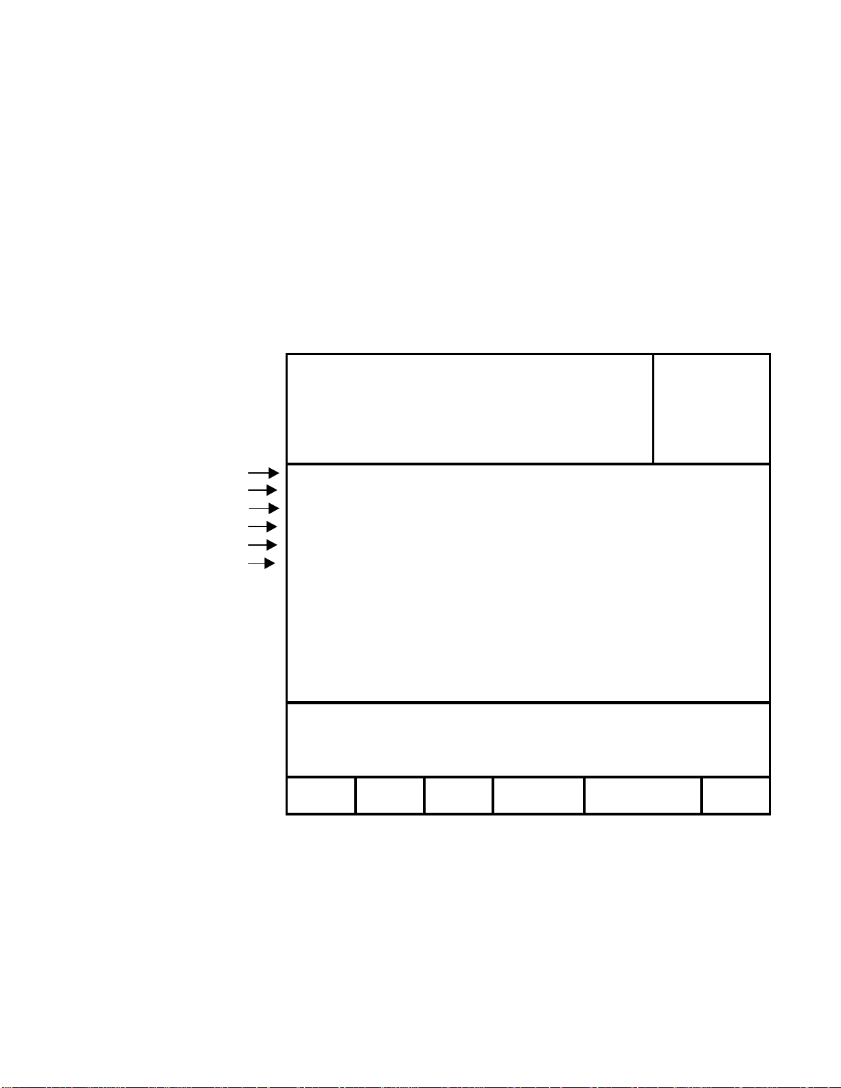
5. SETUP MENU
1. Press [MENU].
The MENU indicator will turn on.
The Display shown in Figure 3 appears.
2. Use the Softkeys to change the desired mode for the desired option.
OR
Turn the Wheel to select the setup option to be changed.
3. Press [ESC] at anytime to exit SETUP MENU.
The MENU indicator will turn off.
4. The curently loaded clips:
The same clip should be loaded on P1 & R1 and on P2 & R2 (for instant replays).
5.
IIff RReeccoorrddeerr cchhaannnneellss aarree iinn rreeccoorrdd,, tthhe
e lleetttteerr ““RR”” iiss ddiissppllaayyeedd
Figure 3
Currently loaded clips
P1 111 Model
R1 R111 DMAT MAV-555
P2 222 Software Ver:
R2 R222 V4.0 040501
SEE SETUP 1 CLIP HANDLE SIZE=02 SECONDS
SEE SETUP 2 PREROLL = 00:00:05:00
SEE SETUP 3 WIND SPEED & MODE = +04, HOLD
SEE SETUP 4 FAST JOG SPEED = 03X PLAY SPEED
SEE SETUP 5
SEE SETUP 6
STANDARD - NTSC
TIME MODE - LTC
AUTOSAVE - ON
CLIP OUT POINT - FREEZE
PLAYLIST OUT POINT - FREEZE
.
.
MAV CONFIGURATION - 2 PROGRAM WITH EFX
RECORD SET & CHANGE EXIT
SETU
The 6 boxes at the bottom of the display show the function for the corresponding Softkeys below them.
These will change depending on what MENU is selected.
On the next few pages are the screens and options that appear when one of the standard selections is
highlighted and what the Softkey display will look like.
DDMMAATT--MMAAVV
CLEA
MENU
99
Page 10
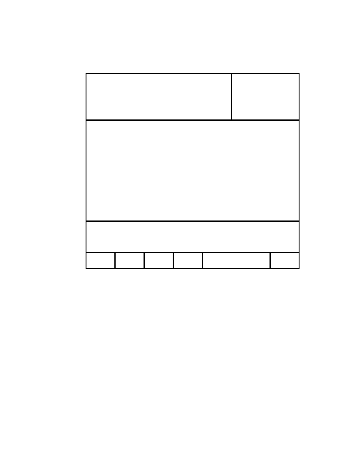
5A. Record Setup
1. Press [MENU].
2. Press [RECORD SETUP].
Currently loaded clips
P1 111 Model
R1 R111 DMAT MA V-555
P2 222 Software Ver:
R2 R222 V4.0 040501
CLIP HANDLE SIZE=02 SECONDS
PREROLL = 00:00:05:00
WIND SPEED & MODE = +04, HOLD
FAST JOG SPEED = 03X PLAY SPEED
STANDARD - NTSC
TIME MODE - LTC
AUTOSAVE - ON
CLIP OUT P O INT - FREEZE
PLAYLIST OUT POINT - FREEZE
MAV CONFIGURATION - 2 PROGRAM WITH EFX
Figure 4
Use the softkeys to create RECORD clips
and start and stop RECORD on R1 and R2
NEW R1 NEW R2 START STOP MAIN
CLIP CLIP RECORD RECORD MENU
3. Press [NEW R1 CLIP] or [NEW R2 CLIP].
4. The display prompts: “ENTER ID: num cap”.
5. Enter a CLIP ID using a PC keyboard (user supplied) or numeric keypad on the ST400.
6. Press [ENTER].
7. The display shows the current Record Loop Length.
Press [ENTER] to accept clip length or enter a new length using the numeric keypad.
8. Press [ENTER] to create the Clip.
The same clip is automatically loaded on the corresponding Play channel: P 1 on R 1, P
2 on R 2.
9. Press [START RECORD].
AUTOSAVE
ON – The clip is saved immediately into the next empty location if both IN & OUT points are set.
OFF – Press [SAVE CLIP] to save the clip
CLIP OUT POINT
FREEZE – Video freezes at the end of clip
OPEN – Video plays through the clip handle
PLAYLIST OUT POINT
FREEZE – Video freezes at the end of clip
OPEN – Video plays through the clip handle
DDMMAATT--MMAAVV
1100
Page 11
S
S
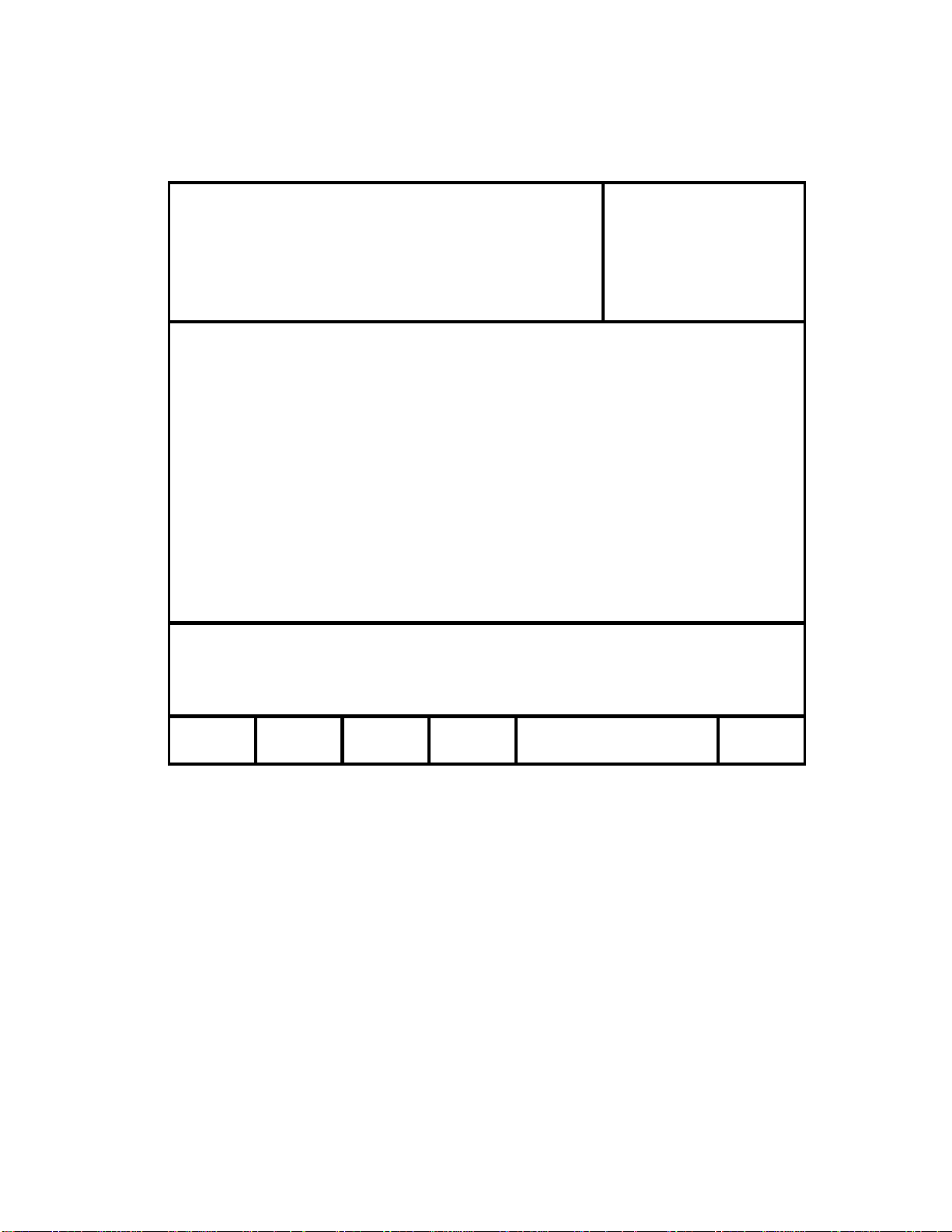
5B. SET & CLEAR
Figure 6
Currently loaded clips
P1 111 Model
R1 R111 DM AT MA V-555
P2 2 2 2 Software V e r:
R2 R222 V4.0 040501
CLIP HANDLE SIZE=02 SECONDS
PREROLL = 00:00:05:00
WIND SPEED & MODE = +04, HOLD
FAST JOG SPEED = 03X PLAY SPEED
STANDARD - NTSC
TIME MODE - LTC
AUTOSAVE - ON
CLIP OUT P OINT - FR EEZE
PLAYLIST OUT POINT - FREEZE
MAV CONFIGURATION - 2 PROGRAM WITH EFX
Make your selection using softkeys
SET CLEAR CLEAR RESET MAIN
DEFLTS MEMORY CLIP
CLIP
MENU
[SET DEFLTS] Set to Factory Defaults.
[CLEAR MEMORY] Clears all memory of the DMAT.
[CLEAR CLIPS] Clears all unprotected Clips and all Playlists on the DMAT & MAV. There is also an
option to save the Playlists – the clips in those Playlists will only exist there. There can be no modifications
made to either those clips or thode Playlists.
[RESET CLIPS] If for some reason a clip, other than the one that’s being recorded, is loaded on the
PlayBack channel, use this key to reset the clip back to the proper Clip.
[MAIN MENU] Return to main menu.
DDMMAATT--MMAAVV
SSEETT && CCLLEEAARR
1111
Page 12
S
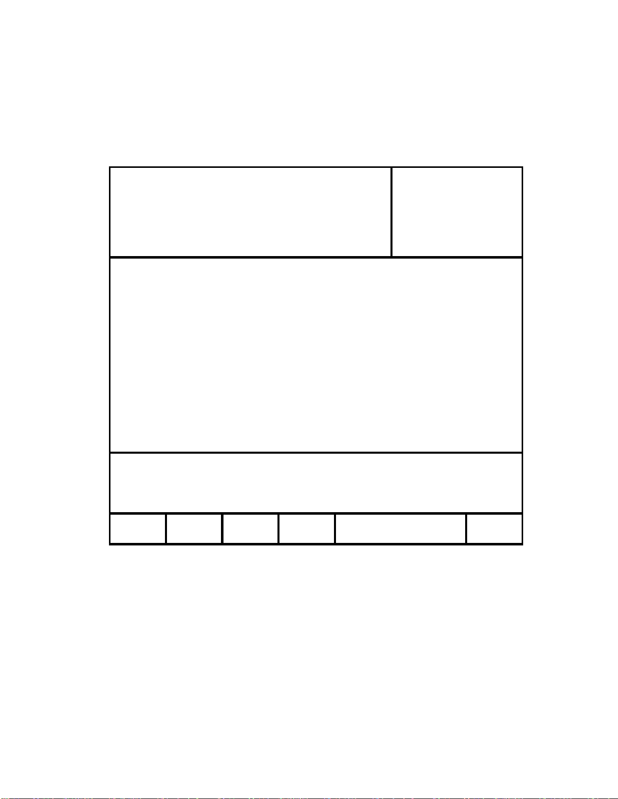
SETUP-1
CLIP HANDLE
Figure 7
Currently loaded clips
P1 111 Model
R1 R111 DM AT MA V-555
P2 2 2 2 Software V e r:
R2 R222 V4.0 040501
CLIP HANDLE SIZE=02 SECONDS
PREROLL = 00:00:05:00
WIND SPEED & MODE = +04, HOLD
FAST JOG SPEED = 03X PLAY SPEED
STANDARD - NTSC
TIME MODE - LTC
AUTOSAVE - ON
CLIP OUT P OINT - FR EEZE
PLAYLIST OUT POINT - FREEZE
MAV CONFIGURATION - 2 PROGRAM WITH EFX
CLIP HANDLE SIZE = 05 SECOND
Enter up to 3 0 se c . u s in g n u m e ric ke ypad
OK CANCEL
Clip Handle-the size of the pad around the saved clip (used for editing clips). 5 seconds means there will
be 5 seconds before the IN point and 5 seconds after the OUT point.
It is possible to view the footage beyond the Clip Handles; a new IN or OUT point can then be set.
Enter up to 30 seconds using the numeric keypad.
Press [OK] to save this Clip Handle or [CANCEL] to return to main menu without changing.
DDMMAATT--MMAAVV
CClliipp HHaannddllee
1122
Page 13
SETUP-2
PREROLL
Figure 8
Currently loaded clips
P1 111 Model
R1 R1 1 1 DMAT MAV-555
P2 2 2 2 Software Ver:
R2 R222 V4.0 040501
CLIP HANDLE SIZE=02 SECONDS
PREROLL = 00:00:05:00
WIND SPEED & MODE = +04, HOLD
FAST JOG SPEED = 03X PLAY SPEED
STANDARD - NTSC
TIME MODE - LTC
AUTOSAVE - ON
CLIP OUT POINT - F REEZE
PLAYLIST OUT POINT - FREEZE
MAV CONFIGURATION - 2 PROGRAM WITH EFX
PREROLL = 00:00:05:00
Enter desired preroll using numeric keypad
OK CANCEL
Enter any time to assign a preroll amount using the numeric keypad.
Press [OK] to save this preroll or [CANCEL] to return to main menu without changing.
DDMMAATT--MMAAVV
PPrreerroollll
1133
Page 14

SETUP-3
WIND SPEED & MODE
Figure 9
Currently loaded clips
P1 111 Model
R1 R111 DM AT MA V-555
P2 222 Software Ver:
R2 R222 V4 .0 0 4 0 5 01
CLIP HANDLE SIZE=02 SECONDS
PREROL L = 00:00:05:00
WIND SPEED & MODE = +04, HOLD
FAST JOG SPEED = 03X PLAY SPEED
STANDARD - NTSC
TIME MODE - LTC
AUTOSAVE - ON
CL IP OUT P O INT - FREEZE
PLAYLIST OUT POINT - FREEZE
MAV CONFIGURATION - 2 PROGRAM WITH EFX
WIND MODE - HOLD
WIND SPEED = +04
HOLD LATCH CHANGE MAIN
SPEED MENU
[HOLD] Press Softkey to select:
HOLD (Fast wind is maintained only while key is depressed.)
[LATCH] Press Softkey to select:
LATCH (Fast wind is initiated and maintained with momentary
key press.)
[CHANGE SPEED] Select fast wind speed (4x to 32x play speed).
[MAIN MENU] Return to MAIN MENU Screen.
DDMMAATT--MMAAVV
WWiinndd SSppeeeedd
1144
Page 15
SETUP-4
FAST JOG SPEED
Figure 10
Currently loaded clips
P1 111 Model
R1 R111 DMAT MAV-555
P2 222 Software Ver:
R2 R222 V4.0 040501
CLIP HANDLE SIZE=02 SECONDS
PREROLL = 00:00:05:00
WIND SPEED & MODE = +04, HOLD
FAST JOG SPEED = 03X PLAY SPEED
STANDARD - NTSC
TIME MODE - LTC
AUTOSAVE - ON
CLIP OUT POINT - FREEZE
PLAYLIST OUT POINT - FREEZE
MAV CONFIGURATION - 2 PROGRAM WITH EFX
FAST JOG SPEED = 03x
Enter from 02x to 20x using numeric keypad
OK CANCEL
Enter a number between 2 and 20 to assign the fast jog speed amount using the numeric keypad.
Press [OK] to save this speed or [CANCEL] to return to main menu without changing.
DDMMAATT--MMAAVV
FFaasstt JJoogg SSppeeeedd
1155
Page 16

SETUP-5
STANDARD
Figure 11
Currently loaded clips
P1 111 Model
R1 R111 D MAT M A V-555
P2 222 Softw a re V er:
R2 R222 V4.0 040501
CLIP HANDLE SIZE=02 SECONDS
PREROLL = 00:00:05:00
WIND SPEED & MODE = +04, HOLD
FAST JOG SPEED = 03X PLAY SPEED
STANDARD - NTSC
TIME MODE - LTC
AUTOSAVE - ON
CLIP OUT P OINT - FR EEZE
PLAYLIST OUT POINT - FREEZE
MAV CONFIGURATION - 2 PROGRAM WITH EFX
STANDARD - NTSC
NTSC PAL MAIN
[NTSC] Select for NTSC Video Standard.
[PAL] Select for PAL Video Standard.
[MAIN MENU] Return to MAIN MENU Screen.
MENU
DDMMAATT--MMAAVV
SSttaannddaarrdd
1166
Page 17

SETUP-6
TIME MODE
Figure 12
Currently loaded clips
P1 111 Model
R1 R111 DMAT MAV-555
P2 222 Software Ver:
R2 R222 V4.0 04050 1
CLIP HANDLE SIZE=02 SECONDS
PRERO LL = 00:00:05:00
WIND SPEED & MODE = +04, HOLD
FAST JOG SPEED = 03X PLAY SPEED
STANDARD - NTSC
TIME MODE - LTC
AUTOSAVE - ON
CLIP OUT POINT - FREEZE
PLAYLIST OUT POINT - FREEZE
MAV CONFIGURATION - 2 PROGRAM WITH EFX
TIME MODE = LTC
LTC VITC TM MAIN
[LTC] Longitudinal Time Code.
[VITC] Vertical Interval Time Code.
[TM] MAV555 internal Timer Data.
[MAIN MENU] Return to Main MENU Screen.
MENU
DDMMAATT--MMAAVV
TTiimmee MMooddee
1177
Page 18
X
X
MAV CONFIG
Figure 13
Currently loaded clips
P1 111 M odel
R1 R111 DM AT MAV-555
P2 222 S oftware Ver:
R2 R22 2 V4 .0 0 4 0 5 0 1
CLIP HANDLE SIZE=02 SECONDS
PREROLL = 00:00:05:00
WIND SPEED & MODE = +04, HOLD
FAST JOG SPEED = 03X PLAY SPEED
STANDARD - NTSC
TIME MODE - LTC
AUTOSAVE - ON
CLIP OUT POINT - F R EEZE
PLAYLIST OUT POINT - FREEZE
MAV CONFIGURATION - 2 PROGRAM WITH EFX
Make your selection using softkeys
2PGM 2PGM PGM & 1 PGM SUPER SLOMO MAIN
W/ EF
[2PGM W/ EFX] 2 record and 2 playback with individual control of each
[2PGM NO EFX] 2 record and 2 playback with individual control of each
[PGM & PVW] 2 record and 2 playback with effects – to allow transitions
[1 PGM] Record and playback on 1 channel – for use with HD MAVs.
[SUPER SLOMO] (See next page)
[MAIN MENU] Back to MAIN MENU screen.
NO EF
PVW MENU
channel.
channel (no efx board on MAV).
between two channels.
DDMMAATT--MMAAVV
MMAAVV CCoonnffiigguurraattiioonn
1188
Page 19

P
SUPER SLO-MO
PGM 1 PB 00:00:02:11
Speed = +0.00
CL IP = 00 1
IN: 00:00 :02:00 3
OUT: 00:00:04:00 4
DUR: 00:00:02:00 5
000 00:04:59:22
001 00:04:59:22
002 00:04:59:22
003 00:04:59:22
004 00:04:59:22
005 00:04:59:22
006 00:04:59:22
007 00:04:59:22 1001T
008 00:04:59:22 1115
Figure 14
R1 00:2 1:20:0 5
CUE = 0
O 00:00:00:00
1
2
6
7
00:00:00:00
00:00:00:00
00:00:00:00
00:00:00:00
00:00:00:00
00:00:00:00
00:00:00:00
LIST = 00
LD 00:0 0:40:0 0
CD 00:00:02:00
#01 out of 05
> > 00:00:00:00
1002T
1004
MELT 1/3 x
CLI
[MELT CLIP] Creates and loads melt clip
CREATING and PLAYING OUT MELT CLIP
1. Select a file to put into the MELT by recalling it or by entering its number on the numeric keypad.
2. Press [ADD ELEMENT] to add the element to the playlist.
3. Repeat steps 1 and 2 until all the clips to be melted are added to the list
NOTE: A playlist can only hold 20 clips. To add more clips to MELT, simply go to the next playlist and
keep adding elements.
4. Press [MELT CLIP]. The display will show “Creating MELT clip” message.
The Melt Clip is loaded. Press [PLAY] to play it out at normal speed or [1/3 x PLAY] to play it out at 1/3
speed.
NOTE: The Melt Clip feature is also available in the 1IN/1OUT configuration.
(SUPER SLOMO and 1IN/1OUT have only one output channel. Therefore, transitions are not available.)
[1/3 x PLAY] Plays back melt clips at 1/3 speed
PLAY
DDMMAATT--MMAAVV
SSuuppeerr SSlloo--MMoo
1199
Page 20

6. OPERATIONS
REVERSE SLO-MO WITH T-BAR
1. Press SLOMO key or move the T-Bar to start variplay. The display shows
SPEED= x.xx where x.xx is the variable speed of the playb ack.
2. Press and hold
reverse direction.
3. Release the key to change the direction to forward.
CREATING CLIPS “ON THE FLY”
1. Press [ALT] + [IN] to mark the IN point using the recorder’s time. The time
shows up in the place for the IN point with the whole area highlighted.
2. Press [ALT]+[OUT] to mark the OUT point using the recorder’s time. The
time shows up in the place for the OUT point with the whole area highlighted.
3. Press [ALT]+[SAVE CLIP] to save marked IN to OUT as a clip. The
highlighted area is cleared upon saving the clip.
4. If the IN and OUT points are not to be saved, press [ESC] to clear IN and OUT
points and the highlighted area.
PROTECTING CLIPS
1. Recall the clip to be protected.
2. Press [SHIFT] + [SAVE CLIP]. The letter ‘p’ shows up next to the clip
number. That means that this clip cannot be deleted from the MAV and the
DMAT until it is unprotected.
3. To unprotect the clip, press [SHIFT] + [SAVE CLIP] again. The letter ‘p’ goes
away. The clip can now be deleted.
DELETING
NOTE: The protected file cannot be deleted until unprotected.
The file that is currently a part of a playlist cannot be deleted until deleted from the playlist.
CLIPS ONE BY ONE
1. Recall the clip to be deleted.
2. Press [DEL] + [SAVE CLIP].
([OK/CANCEL]) Press the appropriate Softkey.
3. Upon pressing Softkey [OK], the clip will be deleted from the MAV and from
the DMAT. The clip will be unloaded, there will be black on the video monitor
and the DMAT display will show “No Clip Loaded”.
[REV] key. The motion starts with the displayed speed in the
DDMMAATT--MMAAVV
2200
Page 21

=
T
T
6A. Creating a Playlist
The two MAV output channels gives two views into the recorded material, a PREVIEW view and
a PROGRAM view. The PROGRAM output is the AIR feed. Only the [PLAY] and T-Bar
SLOMO functions control this output; all other transport functions control the PREVIEW output.
The PREVIEW output is used to view marked Cue Points, view clips or playback a camera feed to
find the desired video.
To switch video to the PROGRAM channel from the PREVIEW channel, the [CUT], [MIX] and
[WIPE] functions are used. The duration of the MIX and the pattern and duration of the WIPE are
definable by pressing [EDIT EFFECT].
Figure 15
PGM 1 PB 00:00:02:11 PVW 2 PB 00:00:02:11
R1 00:21:20:05
CUE = 0
R2 00:21:20:05 00
Speed
CLIP = 0 01
+0.00
01
02
IN: 0 0 :0 0 :02:00 03
OU T : 0 0 :0 0 :04:00 04
DU R: 00:00 :02:00 05
000 00:04:59:22
001 00:04:59:22
002 00:04:59:22
003 00:04:59:22
004 00:04:59:22
005 00:04:59:22
006 00:04:59:22
007 00:04:59:22 1001T
008 00:04:59:22 1115
> > 00:00:00:00
06
07
LIST = 00
LD 00:00:40:00
CD 0 0:00:02 :0 0
01/04 SPD= ----
1002T
1004
SKIP SPEED EDIT
SELEC
EFFEC
00:00:00:00
00:00:00:00
00:00:00:00
00:00:00:00
00:00:00:00
00:00:00:00
00:00:00:00
00:00:00:00
1. Press [GOTO LIST]. Enter list # (0-11) on the numeric keypad.
OR
Press [GOTO LIST] to make that list the current Playlist.
OR
Press [SHIFT] + [GOTO LIST] to GOTO the NEXT List.
2. [ADD ELEMNT] Appends the currently selected/ user entered Clip # to the end of the current
Playlist.
OR
[DELETE ELEMNT] Deletes the currently selected Element (the element of the playlist that is
highlighted).
OR
Press [SHIFT] + [DELETE ELEMNT] to delete the current Playlist (not while in PL mode).
DDMMAATT--MMAAVV
2211
Page 22

3. [INSERT ELEMNT] Insert the current/entered Clip # BEFORE the highlighted element.
4. [CUE LIST] Cues up the list to the first element. Goes to PL (Playlist) mode.
The time next to it is the countdown time for the whole playlist.
5. [SHIFT] + [CUE LIST] Cues the list in Loop mode.
6. [SPEED SELECT] To specify the Slomo Speed of every Playlist element. Press [SPEED
SELECT], then move the T-Bar to set speed. Press [NEXT] to assign the speed and move to the
next element in the list; press [ENTER] to assign the speed and exit Speed Select mode; or press
[ESC] to exit Speed Select mode.
CRT is the Clip’s Running Time: Countdown time for the single element.
List = XX, where XX is the playlist Number, 0-11 (12 Lists Total).
LD is the list duration.
CD is the current clip’s duration.
The current element is highlighted.
In PL mode, both playback channels are used to show video of the Playlist.
P1 will always be AIR channel.
P2 is the PREVIEW channel. (ONLY when [PLAY] is pressed.)
To Exit PL Mode:
1. Press [REC] to switch to EE mode.
2. Press [RECALL CLIP] to recall individual clips and go to CP mode.
Switching to Recorder is not allowed in PL mode.
All transport functions are available in PL Mode.
NOTE: IF Clips or Playlists are deleted on the MAV, they will not be available for playout from
DDMMAATT--MMAAVV
the DMAT-MAV, EVEN IF the Clip name or Play Lists appear there.
2222
Page 23

g
6B. Effects - Press [EDIT EFFECTS] to get to this screen
(Not available in Super Slo-mo configuration)
Figure 16
Element #02
Transition type: 1080
Video transition: 30 frames
Audio transition: 30 frames
Default WIPE type: 0001
Default WIPE len
th: 15 frames
Default MIX length: 15 frames
CUT DEFLT DEFLT CLEAR AV AS-
MIX WIPE SPLIT SIGN
Upper line is the number of the element in the Playlist after which the transition will happen.
The Transition Type is the current effect number. Effect duration is the length of the effect. To
change the length, enter up to 99 frames on the numeric keypad. Press [ENTER].
Press [ASSIGN] to assign the displayed transition to the Playlist element.
Press [ESC] to exit without changing the transition. Default transition is a CUT.
Press [CLEAR] to clear the current transition.
Press [DEFAULT WIPE] or [DEFAULT MIX] to assign the defaults to the playlist.
Press [ALT] + [DEFAULT WIPE] or [ALT] + [DEFAULT MIX] to change the default.
Press [AV SPLIT] Enter separate transition rates for video and audio. Press [AV SPLIT] again to
turn the split off; the indicator will go out and the video and audio durations will be the same.
Press [LAST] and [NEXT] to walk through the elements in the Playlist.
DDMMAATT--MMAAVV
2233
Page 24

If the transition is assigned to an element, all the elements that follow and don’t have transitions
assigned to them will use that transition.
For example:
Element 0 has dissolve transition assigned to it.
Elements 1 & 2 don’t have transitions
Element 3 has a wipe assigned to it
Element 4 has a cut assigned to it
Elements 5 & 6 don’t have transitions.
When the Playlist plays out, the following will happen:
0 Î 1 will dissolve
1 Î 2 will dissolve
2 Î 3 will dissolve
3 Î 4 will wipe
4 Î 5 will cut
5 Î 6 will cut
When the element has a transition assigned to it, the display shows “T” next to the element name.
If the transition is a cut, the display shows “C”.
If there is no transition assigned (default transition), the space next to the Element’s name is blank.
DDMMAATT--MMAAVV
2244
Page 25

7. FUNCTION TABLE
Function Key Press Description
PLAY [PLAY] Puts the currently loaded clip into Play
STOP [STOP] Press once to STILL frame VTR.
Press again to put VTR into STOP mode.
REWIND
FFWD
JOG [JOG] Select JOG mode and enable the Wheel.
SHUTTLE [SHUTTLE] Select SHUTTLE mode and enable the Wheel.
SLOMO
MARK IN POINT [IN] Marks ne w IN point of a Clip
MARK OUT POINT [OUT] Marks new OUT point of a Clip
DELETE
IN POINT
DELETE
OUT POINT
SAVE
CLIP
SAVE
CLIP
NAME
CLIP
RECALL
CLIP
RECUE
CLIP
GOTO IN POINT [SHIFT] +[IN] GOTO the IN Point.
GOTO OUT POINT [SHIFT] +[OUT] GOTO the OUT Point.
RECALL
LAST CLIP
RECALL
NEXT CLIP
MARK CUE POINT [MARK] Marks the recorder’s time into a cue point and advances to the next cue
MARK IN POINT [ALT] +[IN] Marks IN point in any mode
MARK OUT POINT [ALT] +[OUT] Marks OUT point in any mode
RECORD [REC] Returns to EE mode. Unload the clip, loads the same material that is
LAST CUE [LAST] IN PB Mode, search to last cue.
NEXT CUE [NEXT] IN PB Mode, search to next cue.
LAST ELEMENT [LAST] In PL Mode, search to Last Element
NEXT ELEMENT [NEXT] In PL Mode, search to Next Element
[RWD] Press and HOLD to shuttle. Release key to stop. Set WIND speed in
MENU.
[FFWD] Press and HOLD to shuttle. Release key to stop. Set WIND speed in
MENU.
[SLOMO] Press SLOMO to slo-mo the VTR. Turn the Wheel or move the T-Bar to
change the play speed. Press SLOMO to STILL frame OR press any
transport key to exit.
[DEL] + [IN] Delete IN point. (Sets the IN point = IN+CLIP Handle Size-see MENU)
[DEL] + [OUT] Delete OUT point. (Sets the OUT point = OUT + CLIP Handle Size-see
MENU)
[SAVE CLIP] Save IN and OUT as the CURRENT CLIP OR if the Clip # is entered on
the numeric keypad (0-399), it saves it as that number.
[ALT] +
[SAVE CLIP]
[NAME CLIP] Assign an alphanumeric name to the selected CLIP. Type a name using
[RECALL CLIP] Loads the currently selected CLIP OR if the clip # is entered on the
[SHIFT] +
[RECALL CLIP]
[LAST] (In CP Mode) Recalls the Last Clip.
[NEXT] (In CP Mode) Recalls the Next Clip.
Save a clip in any mode.
an attached PC keyboard (user supplied) or numeric ke ypad on the ST400.
Press [ENTER] to assign the name to the Clip.
Press [CLEAR] to erase the name of a Clip.
numeric keypad (0-399), it loads that clip.
Recue the loaded Clip to the beginning.
(ONLY available in CP mode).
(In Edit Effect) Move between playlist’s elements & view transitions
(In Edit Effect) Move between playlist’s elements & view transitions
point.
currently being recorded. Time Code and Video come from the Recorder
VTR.
SCROLL [SCROLL] Scroll through list of clips
GANG AND
PLAYBACK
DDMMAATT--MMAAVV
[GANG] Gangs two playback channels for simultaneous playback.
2255
Page 26

8. SPECIFICATIONS
Power: 90 VAC to 265 VAC adapter supplied with IEC connector
Size: [L” x W” x H”] 12 3/4” x 8” x 1 3/4” (front) 3 5/8” (rear)
[8 5/8” high to top of display]
Weight: 10 lbs.
Rear Panel Connectors: VTR1, 2, 3, 4, 5,6 (All DB9F)
GPI (DBF26F)
Power (DB9M)
SHOTBOX (DB9F)
PBIO (DB9F)
Keyboard (6 pin mini DIN)
Ref. Video In (BNC)
Ground Threaded stud
Display: Large 40 characters by 30 line
Easy to read, back-lit LCD display
Jog/Shuttle Wheel: With mechanical detents
“T”-bar: Slo-mo 0-200% of Play Speed
RS422 SERIAL CONNECTOR 9 Pin D type, female (DB9F)
Pin # 1 Frame Ground 6 Receive Common
2 Receive A Í 7 Receive B Í
3 Transmit B Î 8 Transmit A Î
4 Transmit Common 9 Frame Ground
5 Spare
POWER CONNECTOR 9 Pin D type, male (DB9M)
Pin # 1 +5v DC 6 +5 VDC
2 +5v DC 7 Ground
3 Ground 8 Ground
4 +12 VDC 9 Ground
5 –12 VDC
SHOTBOX RS422 SERIAL CONNECTOR 9 Pin D type, female
Pin # 1 None 6 None
2 None 7 None
3 None 8 None
4 None 9 None
5 None
PBIO RS422 SERIAL CONNECTOR 9 Pin D type, female
Pin # 1 None 6 None
2 None 7 None
3 None 8 None
4 None 9 None
5 None
DDMMAATT--MMAAVV
2266
Page 27

GPI IN/OUT CONNECTOR 26 Pin D type, female (DB26F)
Pin # Function Pin # Function
1 No Connection 14 No Connection
2 No Connection 15 No Connection
3 No Connection 16 No Connection
4 No Connection 17 No Connection
5 No Connection 18 No Connection
6 No Connection 19 No Connection
7 No Connection 20 No Connection
8 No Connection 21 No Connection
9 No Connection 22 No Connection
10 No Connection 23 No Connection
11 No Connection 24 No Connection
12 No Connection 25 No Connection
13 No Connection 26 No Connection
DDMMAATT--MMAAVV
2277
Page 28

9. KEY LAYOUT
DDMMAATT--MMAAVV
2288
Page 29

10. DNF CONTROLS LIMITED WARRANTY
DNF Controls warrants its product to be free from defects in material and workmanship for a period of one
(1) year from the date of sale to the original purchaser from DNF Controls.
In order to enforce the rights under this warranty, the customer must first contact DNF’s Customer Support
Department to afford the opportunity of identifying and fixing the pr oblem without sending the unit in for
repair. If DNF’s Customer Support Department cannot fix the problem, the customer will be issued a
Returned Merchandise Authorization number (RMA). The customer will then ship the defective product
prepaid to DNF Controls with the RMA number clearly indicated on the customer’s shipping document.
The merchandise is to be shipped to:
DNF Controls
12843 Foothill Blvd., Suite C
Sylmar, CA 91342
USA
Failure to obtain a proper RMA number prior to returning the product may result in the return not being
accepted, or in a charge for the required repair.
DNF Controls, at its option, will repair or replace the defective unit. DNF Controls will return the unit
prepaid to the customer. The method of shipment is at the discretion of DNF Controls, principally UPS
Ground for shipments within the United States of America. Shipments to international customers will be
sent via air. Should a customer require the product to be returned in a more expeditious manner, the return
shipment will be billed to their freight account.
This warranty will be considered null and void if accident, misuse, abuse, improper line voltage, fire, water,
lightning or other acts of God damaged the product. All repair parts are to be supplied by DNF Controls,
either directly or through its authorized dealer network. Similarly, any repair work not performed by either
DNF Controls or its authorized dealer may void the warranty.
After the warranty period has expired, DNF Controls offers repair services at prices listed in the DNF
Controls Price List. DNF Controls reserves the right to refuse repair of any unit outside the warranty
period that is deemed non-repairable.
DNF Controls shall not be liable for direct, indirect, incidental, consequential or other types of damage
resulting from the use of the product.
# # #
DDMMAATT--MMAAVV
2299
 Loading...