

Page 1

12843 Foothill Blvd. Suite C
Sylmar, California 91342
V: 818.898.3380
F: 818.898.3360
sales@dnfcontrols.com
Model No. 4000CL-MAV70
400 CLIP FAST ACCESS SYSTEM
for MAV70
USER MANUAL
1 4000CL-MAV70, 400 Clip Fast Access System, for MAV70
Page 2

Table of Contents
1. REVISION HISTORY 3
GETTING STARTED . . . 4
2. SYSTEM
DEFINITIONS 4
3. SYSTEM
4. LOAD
5. RECUE
6. VIEW
7. LEARN 7
8. RECALL 7
ADVANCED FEATURES . . . 8
9. CREATE
10. TRANSFERRING
A. TRANSMIT CUE LIST FUNCTION 9
B. RECEIVE CUELIST FUNCTION 10
REFERENCE . . . 11
11. SETUP
12. FUNCTION
13. SPECIFICATIONS 13
RS422
POWER
GPI
14. DNF
DESCRIPTION 4
INSTALLATION 5
AND PLAY A CLIP 6
THE CURRENTLY LOADED CLIP 6
THE CLIP ID OF THE CURRENTLY LOADED CLIP 6
NEW CLIPS 8
CUELIST 9
MENU 11
TABLE 12
SERIAL CONNECTOR 13
CONNECTOR 13
IN/OUT CONNECTOR 13
CONTROLS LIMITED WARRANTY 14
Manual Version........….……........................................ 3.3 080604
Document ID..................….…..4000CL-MAV70 User Manual.doc
2 4000CL-MAV70, 400 Clip Fast Access System, for MAV70
Page 3

1. REVISION HISTORY
100903 Rev. 3.1 Company header information revised.
112103 Rev. 3.2 Updated Transmit Cue List & Receive Cue List Function description.
Added DNF Controls Limited Warranty.
080604 Rev. 3.3 Added T-bar dimension.
3 4000CL-MAV70, 400 Clip Fast Access System, for MAV70
Page 4

Getting Started . . .
2. SYSTEM DESCRIPTION
The 400 Clip FAST Access System consists of the ST300-SSM VTR Controller and Shotlist
Software. The Video Server must support Sony Disk Protocol.
Upon receipt of the Learn command, the ST300 saves the CLIP IDs of the currently loaded clips,
the current time of each clip, the VTRs they are loaded on and the current GANG mode into the
appropriate Cue Point.
SHOTLIST provides fast access to existing video clips stored on the MAV70.
The SHOTLIST contains up to 400 CLIP IDs, stored in non-volatile memory in the ST300.
Remotely view the CLIP IDs that exist in the Video Server under control.
Any clip in the SHOTLIST can be quickly loaded by simply entering the associated 3-digit
number of its location, then pressing [LOAD]. Press [PLAY] to play the clip. Press [RECUE] to
recue to the beginning of the clip.
DEFINITIONS
Throughout this document the MAV70 will be referred to as “Video Server.”
The ST300-S/SM is referred to as “ST300.”
Words surrounded by brackets, for example, [ENTER], are keys on the ST300.
[XXX] + [XXX] means hold the two keys down simultaneously. XXX= Key name.
4 4000CL-MAV70, 400 Clip Fast Access System, for MAV70
Page 5
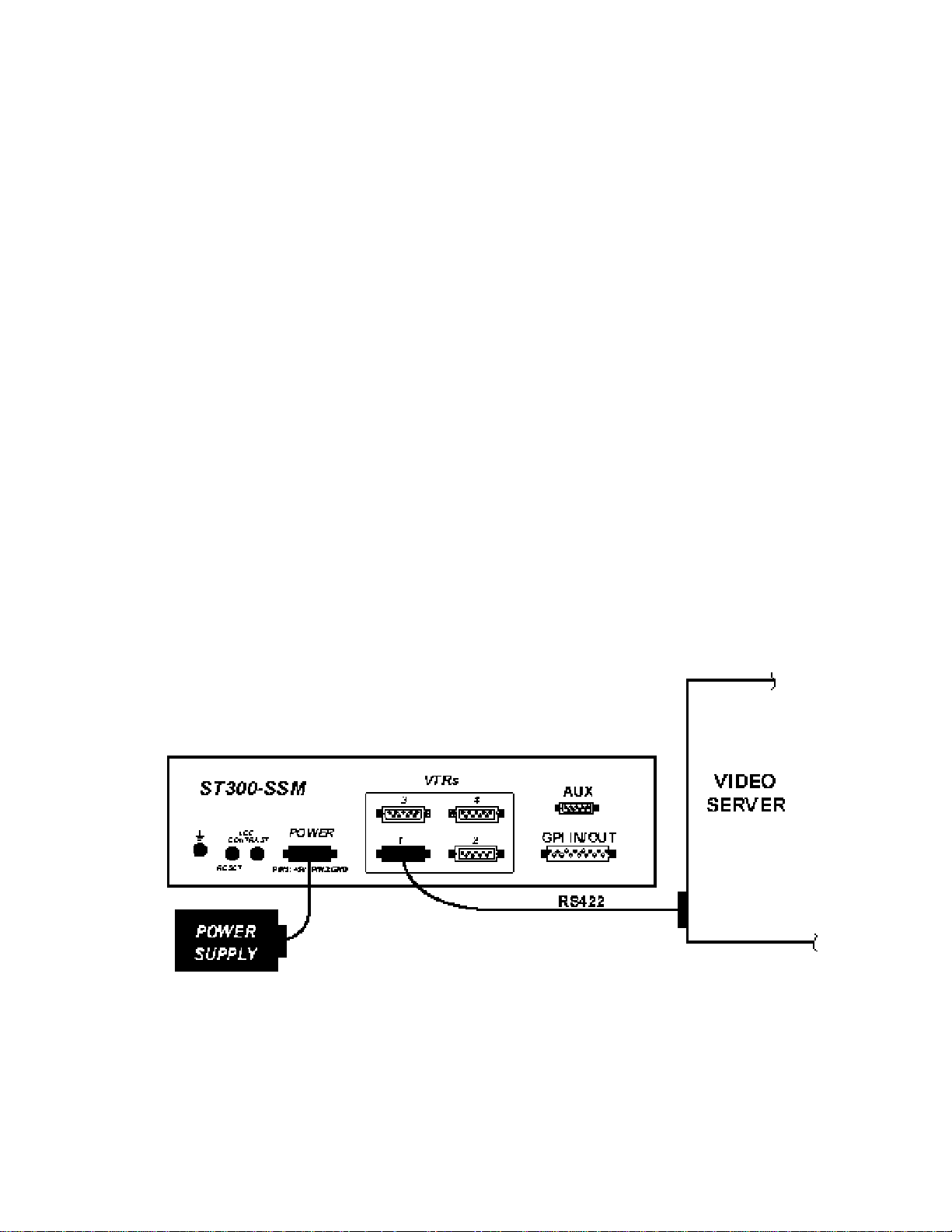
3. SYSTEM INSTALLATION
a. Plug one end of a 9-conductor, RS422 serial cable into the VTR 1 connector on the rear
of the ST300. Plug the other end of the cable into the REMOTE 1 connector on the
Video Server. Plug VTR2 into Remote 2, VTR3 into Remote 3 and VTR4 into Remote
4.
b. Connect the +5, +12, -12 VDC POWER SUPPLY into the POWE R connector on the rear
of the ST300. Plug the Power Supply into an outlet, 90 VAC to 240 VAC.
c. Check SETUP MENU prior to using the ST300 to confirm proper Record mode and other
User settable modes.
Installation is complete.
SYSTEM INSTALLATION DIAGRAM
5 4000CL-MAV70, 400 Clip Fast Access System, for MAV70
Page 6

4. LOAD AND PLAY A CLIP
a. Press [CLIP LIST] to view the list of Clips that exist in the VIDEO SERVER.
The display will show “CREATE NEW CLIP.”
b. Turn the Wheel. The top line of the display will show “xxxxxxxx:”
Where “xxxxxxxx” is the eight-character CLIP ID.
Turn the Wheel clockwise to scroll forward, or counter-clockwise to scroll backward,
through the list of available Clips.
OR
Manually enter a CLIP ID from the ST300 numeric keypad.
Create an ID, with a maximum of eight characters. Press [ENTER].
c. Press [LOAD] to load the current CLIP ID shown on the top line of the display.
d. Press [PLAY].
5. RECUE THE CURRENTLY LOADED CLIP
a. Press [RECUE] to recue the CLIP to its beginning.
(In RECALL mode, [RECUE] will recue to the user defined in time.)
OR
Press [SHIFT] + [RECUE].
The display will show: “xx:xx:xx:xx” (Where xx:xx:xx:xx = Last entered RECUE time.)
“Enter RECUE time”
b. Enter the desired time to search using the ST300’s numeric keypad.
c. Press [ENTER] to go to the entered time.
OR
Press [ESC] to exit without searching
6. VIEW THE CLIP ID OF THE CURRENTLY LOADED
CLIP
Press and hold [SHIFT]; then press and release [LOAD].
The bottom line will show: “Loaded Clip: xxxxxxxx”
where xxxxxxxx is the CLIP ID.
6 4000CL-MAV70, 400 Clip Fast Access System, for MAV70
Page 7

7. LEARN
a. Select the desired Cue Point by pressing [NEXT CUE], [LAST CUE] or by manually
entering the Cue Point using the numeric keypad.
The selected Cue Point number is shown on the bottom line of the display.
b. LOAD a clip (see previous section).
c. Press [SHIFT] + [MARK] to start the LEARN.
The first line of the display will show “Select VTRs:”
The second line of the display will show “Mark-Lrn, ESC-cancel.”
d. Press VTR [1], [2], [3] or [4] to select the VTR to be learned into the current Cue Point.
If the VTRs are ganged, select one VTR that is part of the Gang. The rest of the Gang
will learn automatically.
e. Press [MARK] to complete the LEARN.
OR
Press [ESC] to exit without LEARNING.
The ST300 will: LEARN (save) the VTR Number (1,2,3,4), loaded CLIP ID and current
IN time to the selected Cue Point.
8. RECALL
a. Select the desired Cue Point by pressing [NEXT CUE], [LAST CUE].
OR
By manually entering the Cue Point using the numeric keypad.
The selected Cue Point number is shown on the bottom line of the display.
b. Press [LOAD] on the ST300.
The ST300 will automatically load the Learned clips on the Learned VTRs, cue the clips
to the Learned time, then set the Learned GANG mode.
7 4000CL-MAV70, 400 Clip Fast Access System, for MAV70
Page 8

Advanced Features . . .
9. CREATE NEW CLIPS
a. Press [CLIP LIST]. The CLIP LIST indicator turns on.
The display will show “CREATE NEW CLIP.”
b. Press [LOAD]. The display will show the default CLIP ID.
c. Press [LOAD] to accept the default CLIP ID.
OR
Use [NEXT CUE], [LAST CUE] and Wheel to create a CLIP ID.
Use the [NEXT CUE] and [LAST CUE] keys to position the cursor.
Turn the Wheel to select the desired letter.
OR
Create an ID using the numeric keypad, with a maximum of eight characters.
Press [ENTER].
d. Press [LOAD] to create the selected CLIP ID.
If the selected CLIP ID already exists, a warning message will be displayed. To load the
existing clip, press [ENTER]. Press [ESC] to exit without loading the existing clip.
8 4000CL-MAV70, 400 Clip Fast Access System, for MAV70
Page 9

10. TRANSFERRING CUELIST
a. TRANSMIT CUE LIST FUNCTION
The TRANSMIT CUELIST function allows you to transmit your list of Cue Points to a
PC, using the provided utility software on the PC, or to another ST300. Transfer to a PC
requires OpSuite 3.0 software, which runs on a Windows-based computer. Contact DNF
Controls for more information.
1) TO TRANSMIT CUE POINTS TO THE ST300
a) Connect the VTR4 connector on the rear of the ST300 to the VTR4
connector of the receiving ST300 using an RS422 9-pin cable with TX
and RX lines crossed.
(A “turnaround” cable)
b) Press [MENU].
c) Scroll th e wheel until “Transmit CUE List? YES=Enter, Exit=ESC” is
displayed.
d) Press [ENTER] to start transmitting.
The Display shows “Waiting to transmit” on the first line.
e) When the Receiver is ready, transfer starts automatically.
The Display now shows ”Transmitting cuelist.”
f) After the transfer is over, the display shows “Transfer is over” for one
second, and then shows “Waiting to transmit” again.
g) Connect another ST300 to transmit the list again.
OR
Press [ESC] to exit the MENU mode.
2) TO TRANSMIT CUE POINTS TO THE PC
a) Connect the VTR4 connector on the back of the ST300 to one of the
COM ports on the PC using a RS422 to RS232 adapter.
b) Repeat steps b-g of TO TRANSMIT CUE POINTS TO THE ST300
section.
9 4000CL-MAV70, 400 Clip Fast Access System, for MAV70
Page 10

b. RECEIVE CUELIST FUNCTION
The RECEIVE CUELIST function allows you to receive your list of Cue Points from a
PC or from another ST300. Transfer to a PC requires OpSuite 3.0 software, which runs
on a Windows-based computer. Contact DNF Controls for more information.
1) TO RECEIVE CUE POINTS FROM THE ST300
a) Connect the VTR4 connector on the ba ck of the ST300 from the VTR4
connector of the transmitting ST300 using RS422 9-pin cable with TX
and RX lines crossed. (A “Turnaround” Cable)
b) Press [MENU].
c) Scroll the wheel until “Receive CUE List? YES=Enter, Exit=ESC” is
displayed.
d) Press [ENTER] to start receiving.
The Display shows “Waiting to receive” on the first line.
e) When the Transmitter is ready, transfer starts automatically.
The Display now shows “Receiving cuelist.”
f) After the transfer is over the display shows “Done-Success! Press any
key…”
g) Press any key. The display shows “Receive cuelist?” message.
h) Press [ESC] to exit the MENU mode.
2) TO RECEIVE CUE POINTS FROM THE PC
a) Connect the VTR4 connector on the back of the ST300 to one of the
COM ports on the PC using RS422 to RS232 adapter
b) Repeat steps b-h of the TO RECEIVE CUE POINTS FROM THE
ST300 section.
10 4000CL-MAV70, 400 Clip Fast Access System, for MAV70
Page 11

Reference . . .
11. SETUP MENU
Press [MENU]. The MENU indicator will turn on.
Turn the Wheel to select item to change.
Press [MENU] OR use the Softkeys to change the desired mode for that option.
Turn the Wheel at anytime to select another item.
Press [ESC] at anytime to exit SETUP MENU. The MENU indicator will turn off.
MENU MODES
RECORD
WIND MODE
ST300 SETUP
DISPLAY SOFTWARE
VERSION
RECORD
TRANSMIT CUELIST
RECEIVE CUELIST
(Turning Wheel clockwise)
Press [MENU] to select the desired record mode:
Lockout, Assemble, Crash (Full) or Insert.
Only
display, to toggle Video(V), Audio1(A1), Audio2(A2), Audio3(A3),
Audio4(A4) on/off.
Press Softkey to select:
HOLD
(Fast wind is maintained only while key is depressed.)
OR
LATCH
(Fast wind is initiated and maintained with momentary key press.)
Select fast wind speed (3.9 to 23.7) by pressing Softkey below SPD.
Press Softkey beneath ClearCues to clear all Cue Points to 00:00:00:00.
Press Softkey [YES] when asked “Are You Sure?”
Press Softkey beneath SetDefault to set ST300 to default settings.
Press Softkey [YES] when asked “Are You Sure?”
The version number for the currently installed software is displayed.
Press Softkey to select single button or 2-button recor d.
RECORD = [REC] Only
OR
RECORD = [REC] + [PLAY]
Transmits Cuelist to another ST300 or to a PC.
Receives Cuelist from another ST300 or a PC.
in INSERT mode: Press the associated Softkey, located below the
ST300 SETUP
Clear Cues SetDefault
11 4000CL-MAV70, 400 Clip Fast Access System, for MAV70
Page 12

12. FUNCTION TABLE
Function
Key Press Description
GOTO
ENTERED
TIME
GANG [SHIFT]+[VTR #1]
FFWD
JOG [JOG] Select JOG mode and enable Wheel.
LAST CUE [LAST CUE] Step to the previous Cue Point Location.
NEXT CUE [NEXT CUE] Step to the next Cue Point Location.
RECORD [REC] Places VTR into the Record mode selected by RECORD
[SHIFT] + [RECUE] Search the VTR to the manually entered time.
Use the ST300 numeric keypad. Press [ENTER] or
[RECUE].
NOTE: G
TC or VITC time search.
Individually press the VTR keys to be included in the gang;
OR
[SHIFT]+[VTR #2]
OR
[SHIFT]+[VTR #3]
OR
[SHIFT]+[VTR #4]
[FFWD] Press and HOLD to shuttle. Release key to stop. Set
the LED above the key will turn on. Press the VTR key
again to remove from the gang; the LED above the key will
turn off. Press [ESC] to exit.
The VTR LEDs that are on show the gang.
The flashing LED shows which VTR is currently selected.
WIND Speed in MENU.
MODE in the SETUP MENU. Press [RECORD] or
[RECORD] + [PLAY].
RASS VALLEY GROUP Profile does not support
REWIND
SHUTTLE [SHUTTLE] Select SHUTTLE mode and enable Wheel.
STOP [STOP] Press once to STILL frame VTR.
LOOP [SHIFT] + [PLAY] Play the currently loaded clip in a continuous loop.
TIME MODE
SELECT
[RWD] Press and HOLD to shuttle. Release key to stop. Set
WIND Speed in MENU.
Press again to put VTR into STOP mode.
[TIME MODE] Press to toggle between Timecode (TC), VITC (VT) or
Tape Timer (TM) display modes.
12 4000CL-MAV70, 400 Clip Fast Access System, for MAV70
Page 13

13. SPECIFICATIONS
Power: 90 VAC to 265 VAC 50/60 adapter (supplied)
Size: (L” x W” x H”) 12” x 6” x 1.5” (front) 3.0” (rear)
(T-bar unit is 12.6” long)
Weight: 4 lbs.
Rear Panel Connectors: VTR1, VTR2, VTR3, VTR4 … (All DB9F)
GPI …………………………… (DBF15F)
Power ………………………… (DB9M)
Aux ………………………….. (DB9F)
Display: Easy to read 2-line, back-lit LCD display
(User adjustable contrast)
Jog/Shuttle Wheel: With mechanical detents.
Optional “T”-bar: Slo-mo 0-200% of Play Speed
RS422 SERIAL CONNECTOR
9-Pin D-Type, Female (DB9F)
Pin # 1 Frame Ground 6 Receive Common
2 Receive A Í 7 Receive B Í
3 Transmit B Î 8 Transmit A Î
4 Transmit Common 9 Frame Ground
5 Spare
POWER CONNECTOR
9-Pin D-Type, Male (DB9M)
Pin # 1 +5v DC 6 +5 VDC
2 +5v DC 7 Ground
3 Ground 8 Ground
4 +12 VDC 9 Ground
5 –12 VDC
GPI IN/OUT CONNECTOR
15-Pin D-Type, Female (DB15F)
Pin # Description Function Pin # Description Function
1 GPI 1 Out 9 GPI 1 In Play
2 GPI 2 Out 10 GPI 2 In Stop
3 GPI 3 Out 11 GPI 3 In Recue
4 GPI 4 Out 12 GPI 4 In Next Cue
5 GPI 5 Out 13 GPI 5 In Last Cue
6 GPI 6 Out 14 GPI 6 In Recall
7 GPI 7 Out 15 GPI 7 In
8 Ground
13 4000CL-MAV70, 400 Clip Fast Access System, for MAV70
Page 14

14. DNF CONTROLS LIMITED WARRANTY
DNF Controls warrants its product to be free from defects in material and workmanship for a period of one
(1) year from the date of sale to the original purchaser from DNF Controls.
In order to enforce the rights under this warranty, the customer must first contact DNF’s Customer Support
Department to afford the opportunity of identifying and fixing the pr oblem without sending the unit in for
repair. If DNF’s Customer Support Department cannot fix the problem, the customer will be issued a
Returned Merchandise Authorization number (RMA). The customer will then ship the defective product
prepaid to DNF Controls with the RMA number clearly indicated on the customer’s shipping document.
The merchandise is to be shipped to:
DNF Controls
12843 Foothill Blvd., Suite C
Sylmar, CA 91342
USA
Failure to obtain a proper RMA number prior to returning the product may result in the return not being
accepted, or in a charge for the required repair.
DNF Controls, at its option, will repair or replace the defective unit. DNF Controls will return the unit
prepaid to the customer. The method of shipment is at the discretion of DNF Controls, principally UPS
Ground for shipments within the United States of America. Shipments to international customers will be
sent via air. Should a customer require the product to be returned in a more expeditious manner, the return
shipment will be billed to their freight account.
This warranty will be considered null and void if accident, misuse, abuse, improper line voltage, fire, water,
lightning or other acts of God damaged the product. All repair parts are to be supplied by DNF Controls,
either directly or through its authorized dealer network. Similarly, any repair work not performed by either
DNF Controls or its authorized dealer may void the warranty.
After the warranty period has expired, DNF Controls offers repair services at prices listed in the DNF
Controls Price List. DNF Controls reserves the right to refuse repair of any unit outside the warranty
period that is deemed non-repairable.
DNF Controls shall not be liable for direct, indirect, incidental, consequential or other types of damage
resulting from the use of the product.
# # #
14 4000CL-MAV70, 400 Clip Fast Access System, for MAV70
 Loading...