

Page 1

12843 Foothill Blvd. Suite C
Sylmar, California 91342
V: 818.898.3380
F: 818.898.3360
sales@dnfcontrols.com
Model 3040P/DLO-L
3040P Playlist Playout Controller with
3040P Download Utility and
Asrun Utility
Playlist Playout System
For
Louth Protocol
User Manual
Revision 1.93
Page 2

Page 3

Page 4

Page 5

Table of Contents
1. REVISION HISTORY 3
2. DESCRIPTION 4
DEFINITIONS 5
3. INSTALLATION 5
4. INSTALLATION DIAGRAM 6
5. VIDEO SERVER SETUP 6
5. VIDEO SERVER SETUP 7
6. 3040P SETUP 7
A. LOUTH PORT SETUP 7
B. NTSC/PAL/DF SETUP 7
C. WIND SPEED & MODE 8
D. EXTENDED CLIP IDS 8
E. DSK – PREROLL UPDATE 8
F. PLAY PREROLL 8
G. RECORD PREROLL 8
H. DELETE MODE 9
I. NUMBER OF ELMTS 9
J. AUTOMATIC MODE MANNED/UNMANNED 9
K. AUTOMATIC DURATION 10
L. CLIP ID KEYWORD 10
M. {SERVICE} 11
7. FIGURE 1 - 3040P-L DOWNLOAD MAIN SCREEN LAYOUT 12
8. 3040P MAIN SCREEN LAYOUT 12
8. 3040P MAIN SCREEN LAYOUT 13
A. CLIP REMAINING TIME 13
B. SYNC PRESENCE INDICATOR 13
C. LTC INPUT TIME 13
D. CURRENT ELEMENT WINDOW 13
E. DOWNLOAD MESSAGE WINDOW 13
F. SOFTKEY WINDOW 14
G. PLAYLIST ELEMENT WINDOW 14
9. PLAYOUT A PLAYLIST 15
A. AUTOMATIC PLAYOUT/RECORD 15
B. SEMI-AUTOMATIC PLAYOUT 16
C. SINGLE ELEMENT PLAYOUT/RECORD 17
10. DOWNLOADING A PLAYLIST INTO THE 3040P 18
11. PLAYLIST VIEW MODES 19
12. EDITING A PLAYLIST 19
A. DELETE ELEMENT(S) FROM THE LIST 19
B. EDIT AN EXISTING ELEMENT 20
C. ADD A NEW ELEMENT TO THE LIST 21
13. PLAYLIST VALIDATION 22
A. START VALIDATING A PLAYLIST 22
B. STOP VALIDATING A PLAYLIST 23
C. PLAYLIST VALIDATION DETECTS THE FOLLOWING PROBLEMS WITH AN
ELEMENT 23
14. SEARCH BY TRIGGER TIME 23
15. GANG SETUP 24
16. VTR CONTROL 24
17. OPTIONS 25
THE 3040P/DLO ASRUN TOOL 25
19. SPECIFICATIONS 31
20. KEY LAYOUT 33
21. DNF CONTROLS LIMITED WARRANTY 35
Model 3040P/DLO Page 1 of 35
Page 6

Manual Version .............................................................................................1.93 072707
Document ID........................... 3040P-DLO-L With Download and Asrun Option.doc
Page 2 of 35 Model 3040P/DLO
Page 7

1. REVISION HISTORY
020503 Rev. 1.1 Added Sections PLAYLIST VALIDATION and EDITING A
PLAYLIST, and modified for Phase 2 release.
051403 Rev. 1.2 Modified for Phase 3 release.
070803 Rev. 1.3 Added Section 12.d., COPY AND PASTE AN ELEMENT.
100103 Rev. 1.4 Modified Section 12.c., ADD A NEW ELEMENT TO THE LIST.
Added Section 6.h., CLIP ID KEYWORD.
112103 Rev. 1.5 Added DNF Controls Limited Warranty.
012604 Rev. 1.6 Added Search, Gang, Specification sections.
020705 Rev. 1.7 Revised to conform to software V5.3 011705.
031005 Rev. 1.8 Corrected GPI pin-out.
020806 Rev. 1.9 Minor corrections.
030106 Rev. 1.91 Replaced connection diagram.
110206 Rev. 1.92 Added Asrun Option Section.
072707 Rev. 1.93 Added SP2 pins 7 & 8 warning..
Model 3040P/DLO Page 3 of 35
Page 8

2. DESCRIPTION
The 3040P-L Playlist Playout System with Download Option consists of the ST400 controller with
expanded memory, an internal timecode reader, and Playlist Playout software. The system also
includes “3040P Download Utility,” a Microsoft Windows PC based application. This PC
application allows playlists to be downloaded directly into the 3040P through a COM port on the
PC.
The 3040P-L Playlist Playout System with Download Option will support simultaneous playout of
up to 4 playlists, one per channel. It also provides basic control of up to 2 VTRs.
Each playlist may contain up to 2000 elements. Playlist elements may be COMMENT type,
HARD TRIGGERED type, FOLLOW ALONG type, MANUAL TRIGGERED typ e, or a
combination of types. The playlist may be played out automatically using hard triggers, semiautomatically (a stack of clips played out back to back), or as single events (play out single clip,
then stop).
A playlist element consists of the following fields:
Element Type: 1 = Manual triggered playback element (ML)
Trigger Time (required for Hard Triggered and Follow-Along elements):
Clip ID: Clip ID of video clip that will playout. Clip IDs up to 32
Clip Start Time (SOM): Starting playout point of clip. Set to FF FF FF FF when
Clip Duration: Playout duration of clip. May be less than the actual length of
Title/Comment: This field is used for display purposes only. It may be up to
If an element is a MANUAL TRIGGERED type, then the displayed TIME TRIGGER will be
blank. The contents of the TIME TRIGGER field will not be altered.
If an element is a COMMENT type, then only the Clip ID and Comment fields will be displayed
for that element.
2 = Hard triggered playback element (HT)
3 = Break element
4 = Follow-Along playback element (FA)
5 = Unknown element (UN)
6 = Manual record element (MR)
7 = Hard-triggered record element (HR)
8 = Follow-along record element (FR)
9 = Comment element
This is the time at which playout will begin, referencing the
incoming LTC signal.
characters are supported. Only the first 16 characters are
displayed.
undefined.
the clip. Set to FF FF FF FF when undefined.
32 characters in length. Only the first 16 characters are
displayed.
Page 4 of 35 Model 3040P/DLO
Page 9

DEFINITIONS
Words surrounded by brackets in bold type, [ENTER], are keys on the ST400.
Words surrounded by brackets in bold italic type, {LOAD}, are softkeys on the ST400.
[XXX] + [XXX] means hold the two keys down simultaneously.
3. INSTALLATION
a. Plug one end of a 9-conductor, RS422 serial cable into the VTR 1, VTR2, VTR3, or
VTR4 connector on the rear of the 3040P.
b. Plug the other end of the 9-conductor, RS422 serial cable into the remote control
connector on the Video Server.
c. Connect Video Reference (Black Video) to the REF VIDEO connector on the rear of the
3040P.
d. Connect the facility LTC signal to the LTC Input BNC connector on the rear of the
3040P.
e. Plug the power supply into an outlet, 90 VAC to 240 VAC.
Model 3040P/DLO Page 5 of 35
Page 10
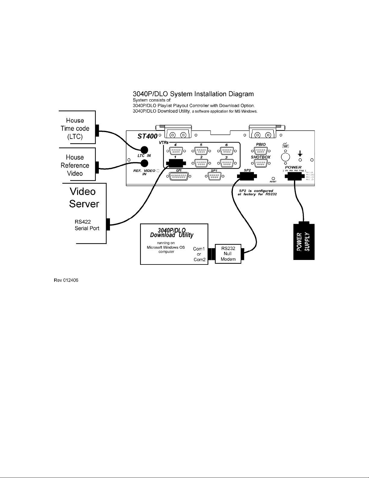
4. INSTALLATION DIAGRAM
Page 6 of 35 Model 3040P/DLO
Page 11

5. VIDEO SERVER SETUP
Select “Louth” or “VDCP” control protocol on the video server. Refer to the manufacturer’s
documentation for configuration instructions and other setups required before usage.
6. 3040P SETUP
Press [MENU]. The current settings of the 3040P are displayed.
Press {EXIT} or [ESC] at any time to exit the Setup Menu.
Turn the wheel to select the setting to change.
a. LOUTH PORT SETUP
Set the Louth Port Number on the video server to be controlled
1) Press [MENU]. The current settings of the 3040P are displayed.
2) Turn the wheel to select LOUTH PORT.
3) Press {CHANGE}.
4) Using the numeric keypad, enter the Louth Port number to be controlled by the
3040P.
5) Press {OUTPUT} to select a playout channel. Th e display will return to the
Main Menu Screen and show the entered setting. Press {EXIT}.
6) Repeat steps 1-4 for each VTR/Port
b. NTSC/PAL/DF SETUP
Set the Video Standard. This setting affects all time computations.
1) Turn the wheel to select STANDARD.
2) Press {CHANGE} to change the current setting. Follow the displayed prompts.
3) Press the {BACK} key to return to the Setup Menu screen.
Model 3040P/DLO Page 7 of 35
Page 12

c. WIND SPEED & MODE
Set the speed and mode of the FFWD and Rewind key. If Hold mode is selected, the
video will move only while the FFWD or RWD key is held down. In Latch mode, the
video will move until [STOP] is pressed.
1) Turn the wheel to select STANDARD.
2) Press {CHANGE} to change the current setting. Follow the displayed prompts.
3) Press {BACK} to return to the Setup Menu screen.
d. EXTENDED CLIP IDS
Set the clip ID size supported by the video server. Set Extended Clips = ON if clips IDs
are greater than 8 characters in length. Set Extended Clips = OFF if All
more than 8 characters in length.
1) Turn the wheel to select EXTENDED IDs.
2) Press {CHANGE} to change the current setting. Follow the displayed prompts.
3) Press {BACK} to return to the Setup Menu screen.
clip IDs are no
e. DSK – PREROLL UPDATE
1) OFF – Will not send update command to server.
2) ON – Will send update command to server.
f. PLAY PREROLL
Set the play command latency for the current channel. The default value is 5 frames. For
Sony MAV-70 use 72 frames. For Profile-XP use 40 frames.
1) Turn the wheel to select PLAY PREROLL.
2) Press {CHANGE} to change the current setting. Follow the displayed prompts.
3) Press {BACK} to return to the Setup Menu screen.
g. RECORD PREROLL
1) Turn the wheel to select RECORD PREROLL.
2) Press {CHANGE} to change the current setting. Follow the displayed prompts.
3) Press {BACK} to return to the Setup Menu Screen.
Page 8 of 35 Model 3040P/DLO
Page 13

h. DELETE MODE
For Automatic Playout Mode only. When DELETE MODE is ON, the playlist element
will be deleted from the playlist after it is played out.
1) Turn the wheel to select DELETE MODE.
2) Press {CHANGE} to change the current setting. Follow the displayed prompts.
3) Press {BACK} to return to Setup Menu Screen.
4) If DELETE MODE= ON, turn the wheel to select “Keep __ Elements after
playout.”
5) Press {CHANGE} to change the current setting. Follow the displayed prompts.
Using the numeric keypad, enter the number of elements to keep after playout.
6) Press {BACK} to return to the Setup Menu screen.
i. NUMBER OF ELMTS
If “DELETE MODE =ON,” enter number of elements to remain in the list after playout.
(10 max.)
j. AUTOMATIC MODE MANNED/UNMANNED
For Automatic mode only. In Unmanned mode, Hard Triggered and Follow-Along
elements are treated as Hard Triggers and played at the entered Trigger Time. All
Manual elements are skipped.
In Manned mode, Hard Triggered elements are played out at their entered Trigger Times,
Follow-Along elements play out back to back, and Manual elements require a PLAY key
press to playout.
1) Turn the wheel to select Automatic mode.
2) Press {CHANGE} to change current setting.
Follow the displayed prompts.
3) Press {BACK} to return to the Setup Menu screen.
Model 3040P/DLO Page 9 of 35
Page 14

k. AUTOMATIC DURATION
1) Turn wheel to select automatic duration.
2) Press {CHANGE} to change current settings.
Follow display prompts.
a) Select {LIST}.
Clips will play using the list’s “Start Time” and “Duration.”
b) Select {SERVER}.
Clips will play using the clip length time from the server.
3) Press {BACK} to return to the Setup Menu screen.
l. CLIP ID KEYWORD
When an element has a clip ID that is in the list of Clip ID keywords, the 3040P will not
attempt to load and play such element.
1) Turn the wheel to select Clip I D keyw ord.
2) Press {CHANGE} to view current list of keywords.
3) Press {EXIT} to return to Setup Menu.
OR
Press {MODIFY} to change the keyword list.
a) Following the instructions on the screen, enter up to 10 keywords.
b) Press {EXIT} to return to the Setup Menu screen.
m. ERROR LED ALERT
When ERROR LED ALERT is set to ON, the 6 LED’s above the softkeys will begin to
flash when an error occurs. The operator may clear the flashing LEDs by accessing the
Error screen ([SHIFT/ESC] + [MENU]) and pressing {LED OFF}.
Page 10 of 35 Model 3040P/DLO
Page 15

n. {SERVICE}
1) {DEFAULTS} Reset to factory settings.
[ENTER] to accept.
[ESC] to cancel.
2) {DEL-LST} Delete playout list for selected channel.
[ENTER] to accept.
[ESC] to cancel.
3) {CLEANUP} Delete all playlists.
[ENTER] to accept.
[ESC] to cancel.
4) {BACK} Return to previous menu.
Model 3040P/DLO Page 11 of 35
Page 16

7. FIGURE 1 - 3040P-L DOWNLOAD MAIN SCREEN LAYOUT
Page 12 of 35 Model 3040P/DLO
Page 17

8. 3040P MAIN SCREEN LAYOUT
The 3040P main screen is made up of 7 individual windows. Refer to Figure 1, 3040P Download
Main Screen Layout (Section 7).
a. CLIP REMAINING TIME
This window is located in the upper left-hand corner of the display. During Automatic,
Semi-Automatic, and Single Element Playout Modes, this display shows the Remaining
Playout Time of the clip. It counts down from the clip duration time to 00:00:00:00,
when playout completes.
When Automatic, Semi-Automatic, and Single Element Playout Modes are disabled, this
window will show the Elapsed Time of the clip in play, wind, jog, and shuttle modes.
b. SYNC PRESENCE INDICATOR
This window is located just to the right of the CLIP REMAINING TIME window. It will
display a non-flashing “REF” when video reference is connected to REF VIDEO IN
connector on the rear of the 3040P. It will display a flashing “REF” when video
reference is not detected.
Video reference is required for Semi-Automatic Playout Mode.
c. LTC INPUT TIME
This window is located in the upper right hand corner of the display. It displays the LTC
INPUT time, the reference time used during Automatic Playout Mode. If the LTC
INPUT signal is disconnected for more than 1 second, the display will show “NO TC
INPUT.”
LTC is required for Automatic-Playout Mode.
d. CURRENT ELEMENT WINDOW
This window is located in the upper left hand corner, just below the CLIP REMAINING
TIME window. This window displays the Playlist number (PL) for the currently selected
channel. PL01 is assigned to VTR1. PL02 is assigned to VTR2. PL03 is assigned to
VTR3. PL04 is assigned to VTR4.
This window also displays the total number of elements in the playlist, as well as the
number of the element that is currently playing or last played out. The Clip ID, Start
Time, and Duration for this element are also shown.
e. DOWNLOAD MESSAGE WINDOW
This window is located in the upper right-hand corner, just below the LTC INPUT TIME
window. All download status messages are displayed here. When a download is in
process, the display will show the total number of elements to download as well as the
number of elements downloaded.
Model 3040P/DLO Page 13 of 35
Page 18

f. SOFTKEY WINDOW
This window is located on the last row of the display. It shows the currently active
functions assigned to the softkeys, which are located just below the display.
g. PLAYLIST ELEMENT WINDOW
This window is located in the middle of the display and shows a maximum of 8 playlist
elements. The Trigger Time, Start Time (SOM), Duration, Trigger Type (two-letter
abbreviation), Clip Name, and Title fields for each playlist element are displayed.
Also, the window has a closed arrow indicator to indicate the Current Element, which is
the currently playing element or the last played element, if playout has completed. It has
an open arrow indicator to indicate the Next Element, the next element to playout. These
indicators are active during Automatic, Semi-Automatic, and Single Playout Mode.
While in any of these modes, pressing [NEXT] or [LAST] will activate VIEW Mode.
To view any element in the playlist, press [NEXT] or [LAST] to step forward or
backwards, respectively. Press [SHIFT] + [NEXT] or [SHIFT] + [LAST] to move one
screenful of elements forward or backward, respectively. Press [ALT] + [NEXT] or
[ALT] + [LAST] to move 100 elements forward or backward, respectively. In the VIEW
Mode, the closed arrow indicator indicates the currently selected playlist element.
Press {VIEW OFF} to exit VIEW mode and display the portion of the playlist that is
currently playing out.
Page 14 of 35 Model 3040P/DLO
Page 19

9. PLAYOUT A PLAYLIST
a. AUTOMATIC PLAYOUT/RECORD
1) PLAYING A LIST
Under Automatic Playout, the list plays out using element time triggers and the
LTC Input time signal.
Hard Trigger elements will begin playout when the LTC Input time matches the
element’s trigger time. Follow-Along elements will begin playout when the
preceding element completes playout. Manual elements will wait for a manual
PLAY key press to begin playout. Refer to Sect i on 6i , A UTOMATIC MODE
MANNED/UNMANNED, for a description of how Follow-Along and Manual
elements are handled.
a) Confirm that LTC time is visible in the upper right hand corner of the
display. If “No LTC Input” is displayed Automatic Playout will not
operate. Check your LTC cable connections.
b) Select channel by pressing VTR key “1”, “2”, “3”, or “4”.
c) In the Setup Menu, set Automatic Mode= Manned or Unmanned.
Refer to Section 6g for more information.
d) In the Setup Menu, set Delete Mode= ON or OFF. If Delete Mode=
ON, enter the number of elements to keep after playout. Refer to
Section 6h for more information.
e) If the chann e l’s playlist is empty, download a playlist into this channel
(Section 10) or manually enter a playlist using the EDIT functions
(Section 12).
e) Press [AUTO] to enable Automatic Playout Mode. The AUTO led will
turn on.
The first element in the list with a trigger time just after the current
LTC Input time will be the “Next Element.” On the display, open
arrows will be placed on both sides of this element.
Playout of the list will continue until all elements are played out or
playout is stopped.
At anytime, press the [SHIFT] + [AUTO] key to stop and disable
Automatic Playout. The AUTO LED will turn off.
Model 3040P/DLO Page 15 of 35
Page 20

2) RECORDING A LIST
a) Select Input Louth Port in the Menu.
b) Follow the same steps as in the previous section to record clips at their
trigger times.
NOTE: 1) There should be at least 5 seconds interval between the elements so
they don’t get down-cut.
2) The elements should be of record type or they will be skipped.
b. SEMI-AUTOMATIC PLAYOUT
Semi-automatic Playout mode is back to back playout of Hard Trigger and Follow Along
playlist elements. The LTC Input signal is not used.
Playout begins at the currently selected element. When this element completes playout,
the next element in the list is automatically played out. This process continues until a
BREAK or UNKNOWN element type is reached, or the end of the playlist is reached.
1) Confirm that Reference Video is connected to the REF VID IN connector on the
rear of the 3040P/DLO. The REF indicator, on the display, to the right of the
LTC Input time, will be on and NOT flashing. If the REF indicator is flashing,
reference video is missing. Semi-Automatic Playout will not operate.
2) Select channel by pressing VTR key “1”, “2”, “3”, or “4”.
3) In the Setup Menu, set Delete Mode= ON or OFF. If Delete Mode= ON, enter
the number of elements to keep after playout. Refer to Section 6h for more
information.
4) If the channel’s playlist is empty, download a playlist into this channel (Section
10) or manually enter a playlist using the EDIT functions (Section 12).
5) Use the [TOP], [NEXT], [LAST], [SHIFT] + [NEXT], [SHIFT] + [LAST],
[ALT] + [NEXT], or [ALT] + [LAST] keys to select the first element to
playout.
6) Press [SEMI AUTO] to enable this playout mode. The SEMI AUTO LED will
turn on.
7) Press [PLAY] to begin playout.
At anytime, press [STOP] to terminate playout.
At anytime, press [SHIFT] + [SEMI AUTO] to disable Semi-Automatic
Playout Mode. The SEMI AUTO LED will turn off.
Page 16 of 35 Model 3040P/DLO
Page 21

c. SINGLE ELEMENT PLAYOUT/RECORD
1) PLAYING A SINGLE ELEMENT
Single Element Playout plays out only one element at a time. When the end of
the element is reached, play out stops and the next element in the list is cued.
a) Confirm that Reference Video is connected to the REF VID IN
connector on the rear of the 3040P/DLO. The REF indicator, on the
display, to the right of the LTC Input time, will be on and NOT
flashing. If the REF indicator is flashing, reference video is missing.
Single Element Playout will not operate.
b) Select channel by pressing VTR key “1”, “2”, “3”, or “4”.
c) In the Setup Menu, set Delete Mode= ON or OFF. If Delete Mode=
ON, enter the number of elements to keep after playout. Refer to
Section 6f for more information.
d) If the channel’s playlist is empty, download a playlist into this channel
(Section 10) or manually enter a playlist using the EDIT functions
(Section 12).
e) Use the [NEXT], [LAST], [SHIFT] + [NEXT], [SHIFT] + [LAST],
[ALT] + [NEXT], and [ALT] + [LAST] keys to select the playlist
element to play.
f) Press [SINGLE] to enable this playout mode. The SINGLE LED will
turn on.
g) Press [PLAY] to begin playout.
At anytime, press [STOP] to terminate playout.
At anytime, press [SHIFT] + [SINGLE] to disable Single Playout
Mode. The SINGLE LED will turn off.
2) RECORDING A SINGLE ELEMENT
a) Select an Input Louth Port in the setup menu.
b) Follow steps a-f in the previous section to enable Single Playout Mode.
Element’s trigger type has to be record type.
c) Press [REC] to start recording the highlighted element.
Model 3040P/DLO Page 17 of 35
Page 22

10. DOWNLOADING A PLAYLIST INTO THE 3040P
Playlist downloads may occur at any time, whether or not a playlist is playing out. The
downloaded playlist is appended to the end of the currently loaded playlist.
If the playlist in the 3040P is empty, Automated Playout Mode may be enabled after the first
element in the playlist file is downloaded into the 3040P.
Each channel will support a playlist containing up to 2000 elements. If the currently available
space in the playlist is less than the number of elements in the download file, the download
process will abort and an error message will be displayed in the download message box on the
3040P’s display.
All downloads into the 3040P/DLO must be initiated from the 3040P Download Utility
application on the PC.
a. Launch the 3040P Download Utility application if it is not already running.
b. Select a Serial Port to use for communication with the 3040P. Using a mouse, click on
“LTP serial Port” option, then select a Com port from a drop-down list.
c. Using a mouse, click on the START DOWNLOAD button.
d. Using a mouse, click on one of the “Channel #” buttons. Select the channel you wish to
download the list into.
e. The “Select a File to Down load” dialog box will be displayed. Using the mouse, click on
the file that you wish to download. The file name will be highlighted.
f. Using the mouse, click on the OPEN button.
The download process will begin.
On the 3040P, the Download message box will show:
“D-load: ON yy” Download process is running on Channel yy (01 thru 04)
“0000 of xxxx” Element 0 of xxxx, the total is being downloaded.
g. Allow the download to proceed until completion.
To abort download prior to completion, press [SHIFT] + [DOWNLOAD] on the 3040P.
Page 18 of 35 Model 3040P/DLO
Page 23

11. PLAYLIST VIEW MODES
To view any element of the playlist in the Playlist Element Window:
Press {VIEW} soft key. If unit is in any play mode, press the [NEXT] or [LAST] key to
enter VIEW mode.
Press [NEXT] to step forward through the playlist.
Press [LAST] to step backwards through the playlist.
Press [SHIFT] + [NEXT] to move forward one screenful of elements.
Press [SHIFT] + [LAST] to move backward one screenful of elements.
Press [ALT] + [NEXT] to move forward 100 elements.
Press [ALT] + [LAST] to move backward 100 elements.
If Automatic, Semi-Automatic, or Single Playout Mode is selected and the list is playing out, the
Playlist Element Window will display the selected part of the playlist without affecting playout of
the playlist.
Press {VIEW OFF} softkey to exit VIEW mode and display the portion of the playlist that is
currently playing out.
If Automatic, Semi-Automatic, and Single Playout Mode are NOT selected, the currently selected
playlist element in the Playlist Element Window will be automatically loaded on the channel for
playout using the basic transport control keys.
12. EDITING A PLAYLIST
a. DELETE ELEMENT(S) FROM THE LIST
1) Press [ALT] + [DEL].
2) On the display, a prompt will ask you to select an element(s) to delete.
Press [1] key to delete the selected element. The display will show the content
of an element you’ve chosen to delete.
Press [ENTER] to delete or [ESC] to cancel.
OR
Press [2] key to delete all elements after highlighted element.
The display will show “Delete all elements after XXXX.” Where XXXX –
selected element number.
Press [ENTER] to delete, or [ESC] to cancel.
OR
Press [3] key to delete all elements before the highlighted element. (Only
available when the list is not playing.)
The display will show “Delete all elements before XXXX.” Where XXXX –
selected element.
Press [ENTER] to delete, [ESC] to cancel.
Model 3040P/DLO Page 19 of 35
Page 24

b. EDIT AN EXISTING ELEMENT
1) Press {EDIT} softkey.
2) The display shows the content of an element you’ve chosen to edit.
3) The following softkeys are also displayed:
{
Å
} Select previous element field to edit
When this softkey is pressed the highlight moves
to the previous element field.
{
Æ
} Select the next element field to edit
When this softkey is pressed the highlight moves
to the next element field.
{C-LIST} View the list of clips available on the server.
When this softkey is pressed, a list of clips is
displayed. Use the wheel to scroll through the
list of clips, press [ENTER] to save a clip name
as part of the element, or [ESC] to return to
editing the element
{MOVE} Moves the element relative to the trigger time in the
list.
{RPLACE} Replace highlighted element with the edited one.
Does not alter the trigger time of an element.
NOTE: For all Hard Triggered and Follow-Along type elements the list is
automatically sorted by Trigger Time.
{TOGGLE} Lets you change the element’s trigger type.
4) Using numeric keyboard on the 3040P or PC keyboard, edit all parts of an
element, then press one of the softkeys to replace the element in the list, or to
move the element to the highlighted position.
Press [ESC] at any time to exit Edit.
Page 20 of 35 Model 3040P/DLO
Page 25

c. ADD A NEW ELEMENT TO THE LIST
1) Press {NEW} softkey.
2) The display will prompt you to enter data for a new element.
3) The new element trigger type defaults to Follow Along if output port, or Follow
Along Record if input port.
4) The 3040P/DLO will automatically calculate the trigger time of the element,
based on the last element’s trigger time and duration.
5) Once the clip name has been entered, the 3040 will get the clip duration from the
server. If there is no communication between 3040P/DLO and server OR if the
clip does not exist, then the duration will default to 30 secs.
6) The following softkeys are also displayed:
{
Å
} Select previous element field to edit
When this softkey is pressed the highlight
moves to the previous element field.
{
Å
} Select the next element field to edit.
When this softkey is pressed the highlight
moves to the next element field.
{C-LIST} View the list of clips available on the server.
When this softkey is pressed a list of clips is
displayed. Use the wheel to scroll through
the list of clips, press [ENTER] to save a
clip name as part of the element, or [ESC] to
return to editing the element.
{INSERT} Insert the edited element relative to the trigger time in
the list.
{APPEND} Append the edited element to the end of the list.
NOTE: For all Hard Triggered and Follow-Along type elements the list is
automatically sorted by Triggr Time.
{TOGGLE} Lets you change the element’s trigger type.
7) Using the numeric keyboard on the 3040P or PC keyboard, edit all parts of an
element, then press one of the softkeys to Replace the element in the list, Insert
or Append the element.
Press [ESC] at any time to exit Edit.
Model 3040P/DLO Page 21 of 35
Page 26

13. PLAYLIST VALIDATION
a. START VALIDATING A PLAYLIST
To start validating a playlist, simply press [VALIDATE]. A prompt on the display will
instruct you to enter “1” or “2”.
PRESS “1” KEY TO VALIDATE ALL UNPLAYED ELEMENTS
This option will validate all elements that have not been played out by the server.
OR
PRESS “2” KEY TO VALIDATE A NUMBER OF ELEMENTS STARTING
FROM THE CURRENT SELECTED ELEMENT
This option will validate the number of elements you enter beginning with the
element currently selected by the arrows.
Press [ESC] to exit without validating.
Once playlist validation has begun, a validate message text will show the validate
progress.
While validating a playlist, you are not allowed to go into the Menu nor are you allowed
to use the [JOG] or [SHUTTLE] keys. However, you are allowed to play, rewind, fast
forward, and stop a clip. You are also allowed to start and stop playing a playlist.
Page 22 of 35 Model 3040P/DLO
Page 27

b. STOP VALIDATING A PLAYLIST
To stop the validating process, simply press [SHIFT] + [VALIDATE]. When the
validate ends, the validate window will clear itself.
c. PLAYLIST VALIDATION DETECTS THE FOLLOWING
PROBLEMS WITH AN ELEMENT
9 Clip name: When the name of the clip does not exist in the video server.
9 Clip Long: When the clip on the server is five frames or more longer than the one
registered in the 3040P.
9 Clip Short: When the clip on the server is five frames or more shorter than the one
registered in the 3040P.
9 Clip Empty: When the duration of the clip in the 3040P is zero frames.
9 Clip Overlap: When the duration of a clip is so long that it overlaps the next clip to
play.
When the clip duration is undefined, the 3040P will copy the duration from the server
into the element.
Since a small portion of the display is used to display an error, when there are two or
more errors, only one will be shown. It is recommended that once the clip is in error the
user verify the other aspects (i.e. trigger time, clip name, etc.) of the clip.
When the 3040PL displays “Many Errors,” it means that the clip has a problem with the
clip name and also with one of its times (i.e. trigger time and/or duration).
14. SEARCH BY TRIGGER TIME
a. Press [SEARCH].
b. The window is displayed that prompts you to enter the trigger time to search by.
c. Enter the triger time using a numeric keypad.
d. Press [ENTER] to search for the element with the entered trigger time.
e. The Element with the entered trigger time becomes the Current Element. If the exact
time is not found, the list is positioned to the element with the closest time after the
entered time.
Model 3040P/DLO Page 23 of 35
Page 28

15. GANG SETUP
a. Press [GANG] key.
b. The Window appears prompting to select Channels to add to / clear from gang.
c. Press [VTR1] thru [VTR4] keys to add the VTR to the gang or clear it from gang.
d. Press [ESC] when done.
When VTRs are ganged, all transport functions apply to all ganged VTRs.
16. VTR CONTROL
Channels 5 and 6 of the 3040P-DLO-L may be used for basic Transport control of Tape Machines.
To control a VTR from Channel 5 (6):
a. Plug 9-pin standard cable into VTR’s “Remote” connector and into VTR 5 (VTR 6)
connector on the back of the 3040.
b. Press VTR [5] (or VTR [6]) key.
c. Use [PLAY], [STOP], [REW], [FWD], [JOG], [SHUTTLE] keys for transport control
of a VTR.
d. Use [RECUE] key to enter time to search to.
e. Use {TC/TM} softkey to toggle between TC and TM time modes.
Page 24 of 35 Model 3040P/DLO
Page 29

17. OPTIONS
The 3040P/DLO ASRUN Tool
Overview:
The 3040P/DLO ASRUN Tool is used to upload a text file (CSV format) to a PC
(computer). Once the file has been uploaded to the PC the information is no longer
available from the 3040P/DLO. The file contains information about the clips that have
played-out from the server that is connected to the 3040P/DLO. The system is set to
upload a list from each channel, therefore there are four “Asrun” files. There is no action
required on the 3040P/DLO to initiate the “Asrun” upload.
Refer to the connection diagram to connect the 3040P/DLO to the PC.
Asrun File format:
Element number, Trigger type, Clip ID, Title, SOM (Time Code), scheduled time (Time of
day), Actual time, Scheduled duration, Actual Duration, Status.
Status:
1. 'G' = GOOD; Element PLAYED OUT properly, received play status from
server.
2. 'S' = SHORT; Playout duration of the element was SHORT.
3. 'A' = ABORTED; Playout for this element was stopped by user.
4. ‘F' = FAIL; Element DID NOT PLAY OUT or did not get play status
from server.
Using the 3040P/DLO ASRUN Tool:
1. From the “Com Port” dropdown menu at the top of the screen, select a COM port.
Ensure that the 3040P/DLO controller is connected to the selected port.
2. Click the “UPLOAD LIST” button to begin the upload process.
3. Select an upload channel (1, 2, 3, or 4) from the popup window.
4. Enter a file name using the popup Save As dialog to save the uploaded data. This is the
only chance to save the file as the data is no longer available from the 3040P/DLO.
5. The upload status will appear on the PC screen and in the status box on the 3040P/DLO.
6. Click the “VIEW LIST” button to view the list you uploaded (OPTIONAL).
7. You may upload a new file for each of the other channels..
OR.
8. Click the “Exit” button to exit the program.
Model 3040P/DLO Page 25 of 35
Page 30

3040P/DLO Asrun Tool
software installation.
Rev 013106
1. Insert the supplied CD-ROM into the cd-rom reader in the computer that will be used
to run the “3040P/DLO Upload Utility” program.
2. The installation will start automatically if the auto-run feature in “Windows” has been
set. If the program does not start by itself double click on the SETUP.EXE file in the
CD-ROM directory.
3. At the “Welcome to the 3040P-DLO UPLOADLOADER TOOL ASRUN SETUP
WIZARD” Screen, click on NEXT
4. At the “Select Destination Folder” screen, click on NEXT to install into the default
directory (recommended). Click on the BROWSE button to install into a directory
other than the default directory.
5. At the “Select Start Menu Folder” screen, click on NEXT to select the default name
(recommended). Click on the BROWSE button to select a name other than the
default name.
6. At the “Ready to install the application” screen, click on INSTALL to continue the
installation. Click on cancel to abort the installation procedure.
7. At the “Completing the 3040P-DLO Uploader Tool Asrun Setup Wizard” screen, click
on FINISH to complete the installation procedure.
8. The installation is now complete. You do not need to restart your computer before
using the “3040P/DLO Upload Utility” program. The default location is
C:\PROGRAMS\DNFControls\3040P/DLO Uploader Tool Asrun.
Page 26 of 35 Model 3040P/DLO
Page 31

Model 3040P/DLO Page 27 of 35
Page 32

18. FUNCTION TABLE
3040P FUNCTIONS
Function Key Press Description
FFWD [FFWD] Activate fast forward transport function. Set WIND SPEED in
MENU for wind speed. Set WIND MODE in MENU for
momentary or latch.
Not available when playlist is playing.
JOG [JOG] Select JOG mode and enable Wheel.
Not available when playlist is playing.
PLAY [PLAY] Play a single Clip or a playlist (if Semi-Auto or Single LED is
ON).
REWIND [RWD] Activate rewind transport function. Set WIND SPEED in
MENU for wind speed. Set WIND MODE in MENU for
momentary or latch.
Not available when playlist is playing.
SHUTTLE [SHUTTLE] Select SHUTTLE mode and enable Wheel.
Not available when playlist is playing.
ENABLE
AUTOMATED
PLAYOUT/
RECORD
[AUTO] Press this key to enable automated playout of the playlist based
upon element time triggers. The AUTO LED will turn on.
An LTC signal must be connected to the input LTC BNC
connector on the rear of the 3040P.
DISABLE
AUTOMATED
PLAYOUT/
RECORD
DELETE
ELEMENTS
ENABLE SEMIAUTOMATIC
PLAYOUT
DISABLE SEMIAUTOMATIC
PLAYOUT
ENABLE
SINGLE
PLAYOUT/
RECORD
DISABLE
SINGLE
PLAYOUT/
RECORD
VALIDATE
ELEMENTS
[SHIFT] + [AUTO] Press this key to disable automated playout of the playlist. The
AUTO LED will turn off.
[ALT] + [DEL] Delete element(s) from the Playlist.
[SEMI AUTO] Press to enable the playout of clips back to back. Semi Auto
LED turns on. Black Burst must be connected to ref. Video
connector on the 3040.
[SHIFT] +
[SEMI AUTO]
[SINGLE] Press to enable the playout of clips back to back. Single LED
[SHIFT] + [SINGLE] Press to disable single playout. The Single LED will turn off.
[VALIDATE] Verify the existence of clips in the list as well as their duration.
Press to disable semiautomatic playout. The Semi Auto LED
will turn off.
turns on. Black Burst must be connected to ref. Video connector
on the 3040.
Validate LED turns on.
Page 28 of 35 Model 3040P/DLO
Page 33

3040P FUNCTIONS
Function Key Press Description
ABORT
VALIDATION
STOP [STOP] Stop playout of the clip or of the playlist (in Semi-Auto or Single
ABORT
DOWNLOAD
RECORD [RECORD] Record a Single Clip.
GANG [GANG] Sets/clears VTRs from gang.
SEARCH
By Trigger Time
MONITOR
PLAYLIST
PLAYOUT
VIEW NEXT
PLAYLIST
ELEMENTS
VIEW LAST
PLAYLIST
ELEMENTS
VIEW NEXT
PAGE OF
PLAYLIST
ELEMENTS
VIEW LAST
PAGE OF
PLAYLIST
ELEMENTS
JUMP
FORWARD 100
ELEMENTS
JUMP
BACKWARDS
100 ELEMENTS
MONITOR
PLAYLIST
PLAYOUT
TOP
[SHIFT] + [VALIDATE] Stop validation of the playlist.
Validate LED turns off.
mode).
[SHIFT] +
[DOWNLOAD]
[SEARCH] Search for element by trigger time.
{VIEW}
[NEXT] Step forward through the playlist, one element at a time until the
[LAST] Step backward through the playlist, one element at a time, until
[SHIFT] + [NEXT] Page forward through the playlist, one screen full of elements at a
[SHIFT] + [LAST] Page backward through the playlist, one screen full of elements at
[ALT] + [NEXT] Jump forward 100 elements from the current location in the
[ALT] + [LAST] Jump backward 100 elements from the current location in the
{VIEW OFF}
{TOP}
Stop downloading a playlist.
Press this key to enter view mode.
Use the [NEXT}, [LAST], or [SEARCH] key to view the list.
end of the playlist is reached. If in any playout mode, this will
enable VIEW mode, if not already enabled. It will not affect
playlist playout.
the beginning of the playlist is reached. If in any playout mode,
this will enable VIEW mode, if not already enabled. It will not
affect playlist playout.
time until the end of the playlist is reached. If in any playout
mode, this will enable VIEW mode, if not already enabled. It
will not affect playlist playout.
a time until the beginning of the playlist is reached. If in any
playout mode, this will enable VIEW mode, if not already
enabled. It will not affect playlist playout.
playlist, until the end of the playlist is reached. If in any playout
mode, this will enable VIEW mode, if not already enabled. It
will not affect playlist playout.
playlist, until the beginning of the playlist is reached. If in any
playout mode, this will enable VIEW mode, if not already
enabled. It will not affect playlist playout.
Press this key to exit VIEW mode and monitor the current
playout location in the playlist.
Cue to the top of the list. Only available when list is not playing.
Model 3040P/DLO Page 29 of 35
Page 34

3040P FUNCTIONS
Function Key Press Description
CREATE NEW
ELEMENT
EDIT EXISTING
ELEMENT
CUE
END
{NEW}
{EDIT}
{CUE}
{END}
Press the {NEW}key to enter add element dialogue
Press the {EDIT}key to enter edit element dialogue
Cue the current clip to its Start (SOM) time. Only available
when list is not playing.
Cues the last element in the list. Only available when list is not
playing.
Page 30 of 35 Model 3040P/DLO
Page 35

19. SPECIFICATIONS
Power: 90 VAC to 265 VAC adapter supplied with IEC connector
APX Model #AP4108
+5v @ 4A, +12v @ 1.0A, -12V @ 0.6A
Size: [L” x W” x H”] 12 3/4” x 8” x 1 3/4” (front) 3 5/8” (rear)
[8 5/8” high to top of display]
Weight: 10 lbs.
Rear Panel Connectors: VTR1, 2, 3, 4, 5, 6 (All DB9F)
GPI (DBF25F)
Power (DB9M)
SHOTBOX (DB9F)
PBIO (DB9F)
SP1 (DB9F)
Keyboard (6-pin mini DIN)
SP2 (DB9F)
Ref. Video In (BNC)
Ground Threaded stud
LTC IN (BNC)
Display: Easy to read, back-lit LCD display
Jog/Shuttle Wheel: With mechanical detents
RS422 SERIAL CONNECTOR
9-Pin D-Type, Female (DB9F)
Pin # 1 Frame Ground 6 Receive Common
2 Receive A Í 7 Receive B Í
3 Transmit B Î 8 Transmit A Î
4 Transmit Common 9 Frame Ground
5 Spare
POWER CONNECTOR
9-Pin D-Type, Female (DB9M)
Pin # 1 +5v DC 6 +5 VDC
2 +5v DC 7 Ground
3 Ground 8 Ground
4 +12 VDC 9 Ground
5 –12 VDC
Model 3040P/DLO Page 31 of 35
Page 36

SP2 CONNECTOR, RS232 PINOUT
NOTE: Do not use pins 7 or 8. These pins are used for internal functions.
9-Pin D-Type, Female
Pin # 1 Do not use 6 Do not use
2 Receive Í 7 Do not use
3 Transmit Î 8 Do not use
4 Do not use 9 Do not use
5 Ground
GPI IN/OUT CONNECTOR
26-Pin D-Type, Female (DB26F)
Pin # Function Pin # Function
1 Not Used 14 GPI #5 – Stop
2 Not Used 15 GPI #6 – List Top
3 Not Used 16 GPI #7 – Last
4 Not Used 17 GPI #8 – Next
5 Not Used 18 Ground
6 Not Used 19 +5V
7 Not Used 20 +5V
8 Not Used 21 Not Used
9 Ground 22 Not Used
10 GPI #1 – Start Automatic Playout 23 Not Used
11 GPI #2 – Select Semi-automatic Playout Mode 24 Not Used
12 GPI #3 – Selec t Singl e Pl ay ou t Mode 25 Not Used
13 GPI #4 – Play 26 Ground
Page 32 of 35 Model 3040P/DLO
Page 37

20. KEY LAYOUT
Model 3040P/DLO Page 33 of 35
Page 38

Page 34 of 35 Model 3040P/DLO
Page 39

21. DNF CONTROLS LIMITED WARRANTY
DNF Controls warrants its product to be free from defects in material and workmanship for a period of one
(1) year from the date of sale to the original purchaser from DNF Controls.
In order to enforce the rights under this warranty, the customer must first contact DNF’s Customer Support
Department to afford the opportunity of identifying and fixing the pr oblem without sending the unit in for
repair. If DNF’s Customer Support Department cannot fix the problem, the customer will be issued a
Returned Merchandise Authorization number (RMA). The customer will then ship the defective product
prepaid to DNF Controls with the RMA number clearly indicated on the customer’s shipping document.
The merchandise is to be shipped to:
DNF Controls
12843 Foothill Blvd., Suite C
Sylmar, CA 91342
USA
Failure to obtain a proper RMA number prior to returning the product may result in the return not being
accepted, or in a charge for the required repair.
DNF Controls, at its option, will repair or replace the defective unit. DNF Controls will return the unit
prepaid to the customer. The method of shipment is at the discretion of DNF Controls, principally UPS
Ground for shipments within the United States of America. Shipments to international customers will be
sent via air. Should a customer require the product to be returned in a more expeditious manner, the return
shipment will be billed to their freight account.
This warranty will be considered null and void if accident, misuse, abuse, improper line voltage, fire, water,
lightning or other acts of God damaged the product. All repair parts are to be supplied by DNF Controls,
either directly or through its authorized dealer network. Similarly, any repair work not performed by either
DNF Controls or its authorized dealer may void the warranty.
After the warranty period has expired, DNF Controls offers repair services at prices listed in the DNF
Controls Price List. DNF Controls reserves the right to refuse repair of any unit outside the warranty
period that is deemed non-repairable.
DNF Controls shall not be liable for direct, indirect, incidental, consequential or other types of damage
resulting from the use of the product.
# # #
Model 3040P/DLO Page 35 of 35
 Loading...