

Page 1
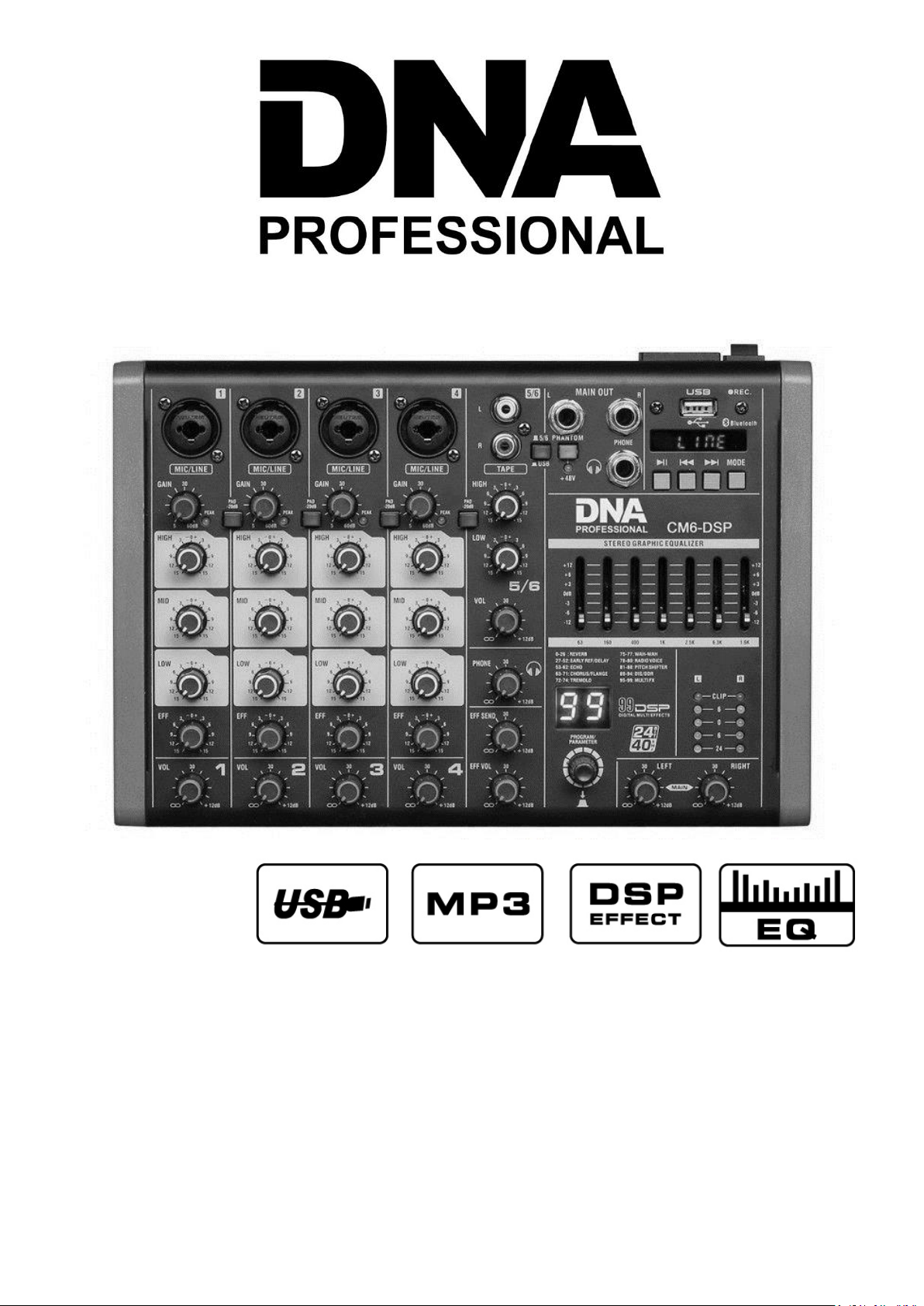
CM4/6/8-DSP
Instrukcja obsługi
User Manual
Page 2
POLSKI
Budowa i funkcje
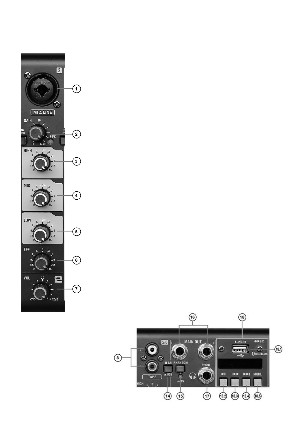
1. COMBO.
Użyj tego wejścia combo XLR/Jack aby podłączyć mikrofon do miksera.
2. GAIN.
Potencjometr GAIN reguluje wejściowy poziom sygnału na dany kanał, dotyczy to za-
równo mikrofonów, jak i innych urządzeń wejściowych.
3. HIGH.
Za pomocą tego potencjometru regulujesz poziom wysokich tonów na każdym z kanałów. Pozycja podstawowa jest na godzinie 12-tej, przekręcenie w lewo powoduje zmniejszenie ilości wysokich tonów, w prawo zwiększenie.
4. MID.
Za pomocą tego potencjometru regulujesz poziom średnich tonów na każdym z kanałów.
Pozycja podstawowa jest na godzinie 12-tej, przekręcenie w lewo powoduje zmniejsze-
nie ilości średnich tonów, w prawo zwiększenie.
5. LOW.
Za pomocą tego potencjometru regulujesz poziom niskich tonów na każdym z kanałów.
Pozycja podstawowa jest na godzinie 12-tej, przekręcenie w lewo powoduje zmniejsze-
nie ilości niskich tonów, w prawo zwiększenie.
6. EFF.
Potencjometr EFF reguluje poziom efektu dodawanego do odpowiadającego kanału.
7. VOL.
Za pomocą tego potencjometru kontrolujesz głośność danego kanału.
8. L i R gniazda wejściowe RCA.
Gniazda kompatybilne z wtyczkami phone RCA i urządzeniami o poziomie liniowym
600Ω.
9. HIGH/LOW.
Potencjometry regulujące barwę dźwięku kanału 5/6 (3/4 lub 7/8).
10. VOL.
Za pomocą tego potencjometru kontrolujesz głośność kanału 5/6 (3/4 lub 7/8).
11. PHONE.
Za jego pomocą regulujesz głośność słu-
chawek.
12. EFF SEND.
Reguluje głębię wychodzącego efektu.
13. EFF VOL.
Reguluje poziom przekazywanego efektu.
Page 3
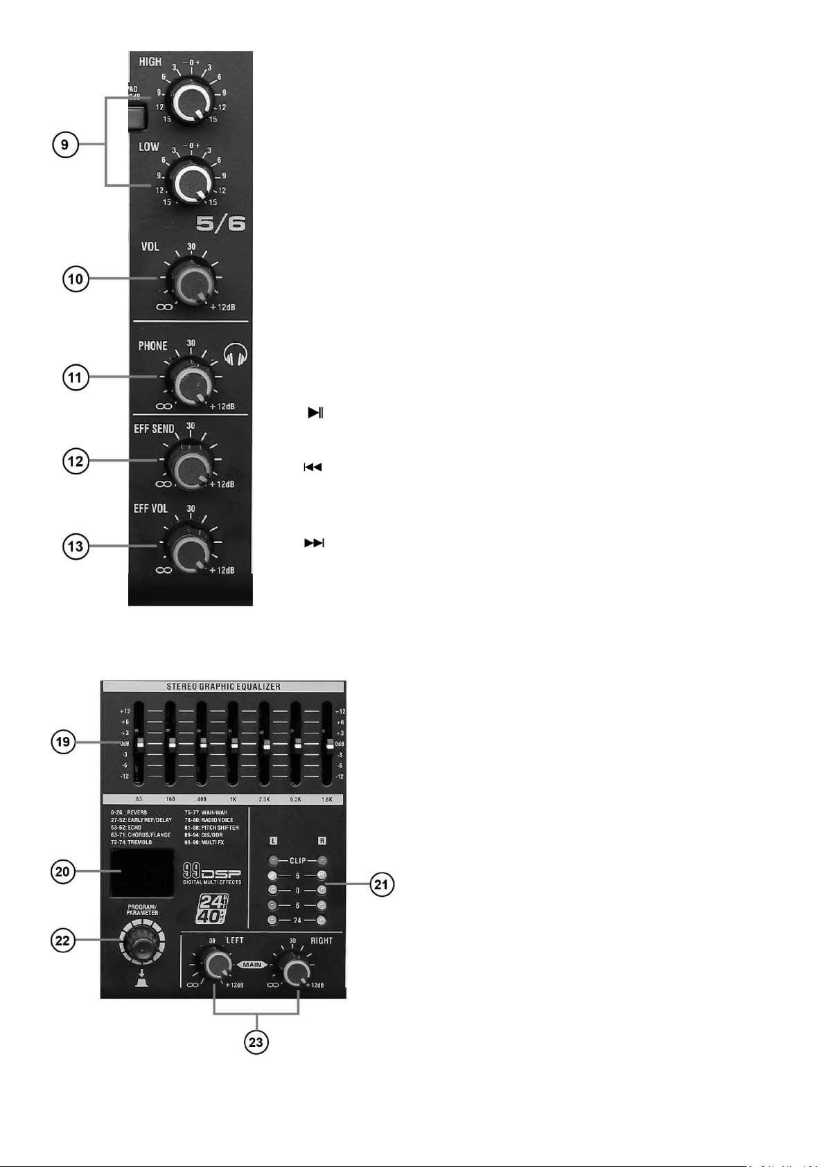
14. PRZEŁĄCZNIK 5/6 (3/4 lub 7/8) i USB.
Za jego pomocą decydujesz, czy sygnał na kanale 5/6 (3/4 lub 7/8) pochodzi z wej-
ścia liniowego czy z odtwarzacza.
15. PHANTOM +48V.
Włącza/wyłącza zasilanie Phantom na wszystkich kanałach mikrofonowych.
16. L i R MAIN OUT.
Główne wyjścia sygnałowe, jack 6,3 mm.
17. PHONE.
Wyjście stereo do podłączenia słuchawek (nominalna impedancja / poziom wyj-
ściowy 3mW40Ω).
18. ODTWARZACZ USB.
Sekcja odtwarzacza do podłączenia osobnego źródła USB.
18.1 Gniazdo USB do włożenia nośnika.
18.2 Play/Pause
Przycisk kontrolny do rozpoczynania i zatrzymania odtwarzania.
18.3
Za pomocą tego przycisku cofasz utwór (krótkie wciśnięcie), lub zmniejszasz gło-
śność (długie wciśnięcie).
18.4
Za pomocą tego przycisku przełączasz utwór na kolejny (krótkie wciśnięcie), lub
zwiększasz głośność (długie wciśnięcie).
18.5 MODE.
W mikserze są następujące tryby: USB, BLUE, LOD, ONE, ALL. Wciśnij przycisk aby wybrać tryb, który chcesz. BLUE:
wyszukaj urządzenie na swoim telefonie lub innym urządzeniu Bluetooth.
19. Korektor graficzny.
Reguluje barwę sygnału wysyłanego na sumę, regulacja następuje na poziomie 63, 160, 400, 1k, 2,5k, 6,3k MHz.
20. Wyświetlacz efektu.
Na nim pojawia się numer wybranego efektu.
21. Poziom sygnału.
Diody wskazują poziom wysterowania sygnału, jeśli poziom
dociera do pola CLIP sygnał będzie zniekształcony, należy
zmienić ustawienia GAIN i Volume.
22. Pokrętło efektów i parametrów.
Za jego pomocą wybierasz efekt, po wybraniu pożądanego
efektu wciśnij pokrętło aby zatwierdzić.
23. Pokrętła głównego sygnału L i R.
Reguluje poziom głośności na lewym i prawym kanale.
Page 4
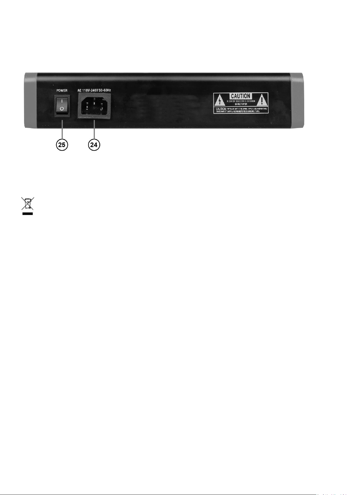
24. Złącze zasilania.
Służy do podłączenia zasilania do miksera za pomocą przewodu IEC.
25. Przełącznik zasilania.
Przełącz go, aby włączyć zasilanie.
Informacja o zużytym sprzęcie elektrycznym i elektronicznym
UWAGA! URZĄDZENIA NIE WOLNO WYRZUCAĆ DO ODPADÓW DOMOWYCH.
To oznaczenie oznacza, że produkt nie może być wyrzucany razem z odpadami domowymi w całej UE. W celu
zapobiegnięcia potencjalnym szkodom dla środowiska lub zdrowia, zużyty produkt należy poddać recyklingowi.
Zgodnie z obowiązującym prawem, nie nadający się do użycia sprzęt elektryczny i elektroniczny należy zbierać
osobno, w specjalnie do tego celu wyznaczonych punktach zbierania zużytego sprzętu, celem ich przetworzenia i ponownego wykorzystania na podstawie obowiązujących norm ochrony środowiska.
Głównym celem regulacji europejskich oraz krajowych jest ograniczenie ilości odpadów powstałych ze zużytego sprzętu
elektrycznego i elektronicznego, zapewnienie odpowiedniego poziomu jego zbierania, odzysku i recyklingu oraz zwiększenie świadomości społecznej o jego szkodliwości dla środowiska naturalnego, na każdym etapie użytkowania sprzętu
elektrycznego i elektronicznego. W związku z powyższym należy wskazać, iż gospodarstwa domowe spełniają kluczową
rolę w przyczynianiu się do ponownego użycia i odzysku, w tym recyklingu zużytego sprzętu. Użytkownik sprzętu przeznaczonego dla gospodarstw domowych jest zobowiązany po jego zużyciu do oddania zbierającemu zużyty sprzęt elektryczny i elektroniczny. Należy jednak pamiętać, aby produkty należące do grupy sprzętu elektrycznego lub elektronicznego utylizowane były w uprawnionych do tego punktach zbiórki.
Page 5
ENGLISH
Structure and features
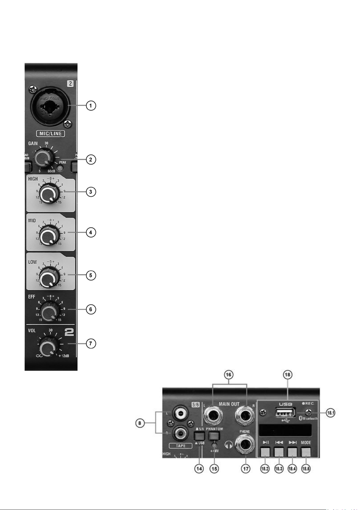
1. COMBO
Use this XLR/Jack combo input to connect the microphone to the mixer.
2. GAIN.
The GAIN potentiometer adjusts the input signal level per channel and it applies to both
microphones and other input devices.
3. HIGH.
With this potentiometer you adjust the treble level on each channel. The base position
is at 12 o'clock, turning it to the left reduces the treble, to the right – increases it.
4. MID.
With this potentiometer you adjust the midrange level on each channel. The base position is at 12 o'clock, turning it to the left reduces the midrange, to the right – increases
it.
5. LOW.
With this potentiometer you adjust the bass level on each channel. The base position
is at 12 o'clock, turning it to the left reduces the amount of bass, to the right – increases
it.
6. EFF.
The EFF potentiometer adjusts the level of the effect added to the corresponding channel.
7. VOL.
With this potentiometer you control the volume of a channel.
8. L and R – RCA input sockets.
Sockets compatible with phone RCA plugs and devices with 600Ω line level.
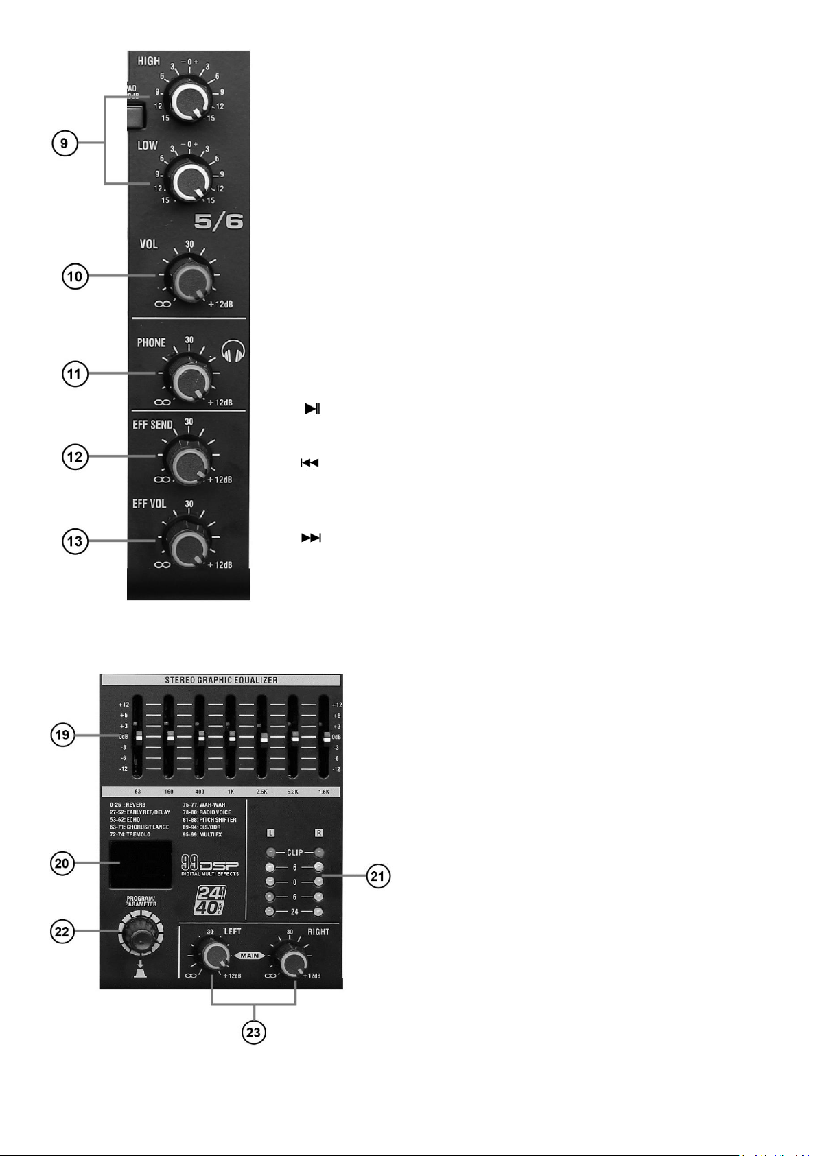
9. HIGH/LOW.
Potentiometers for adjusting the timbre of channel 5/6 (3/4 or 7/8).
10. VOL.
With this potentiometer you control the volume of channel 5/6 (3/4 or 7/8).
11. PHONE.
You use it to adjust the volume of the
headphones.
12. EFF SEND.
It adjusts the depth of the output effect.
13. EFF VOL.
It regulates the level of transmitted effect.
Page 6
14. SWITCH 5/6 (3/4 or 7/8) and USB.
With it, you decide whether the signal on channel 5/6 (3/4 or 7/8) comes from
the line input or from the player.
15. PHANTOM +48V.
Enables/disables Phantom power on all microphone channels.
16. L and R MAIN OUT.
Main signal outputs, 6.3 mm jack.
17. PHONE.
Stereo output for connecting headphones (nominal impedance / output level
3mW40Ω).
18. USB PLAYER.
Player section for connecting a separate USB source.
18.1 USB socket for inserting compatible device with media files.
18.2 Play/Pause
Control button for starting and stopping playing back.
18.3
Use this button to go to a previous track (short press) or lower the volume (long
press).
18.4
Use this button to go to a next track (short press) or increase the volume (long
press).
18.5 MODE
The mixer has the following modes: USB, BLUE, LOD, ONE, ALL. Press the button to select the mode you want. BLUE:
search for the device on your phone or other Bluetooth device.
19. Graphic equalizer.
Adjusts the timbre of the signal sent to the sum, the adjustment occurs at 63, 160, 400, 1k, 2.5k, 6.3k MHz.
20. Effect display.
The number of the selected effect appears on it.
21. Signal level.
The LEDs indicate the level of signal, if the level reaches
the CLIP field the signal will be distorted, change the GAIN
and Volume settings.
22. Effects and parameter potentiometer.
With it you select an effect, after selecting the effect press
the potentiometer to confirm.
23. L and R main signal potentiometers.
Adjusts the volume level on the left and right channels.
Page 7
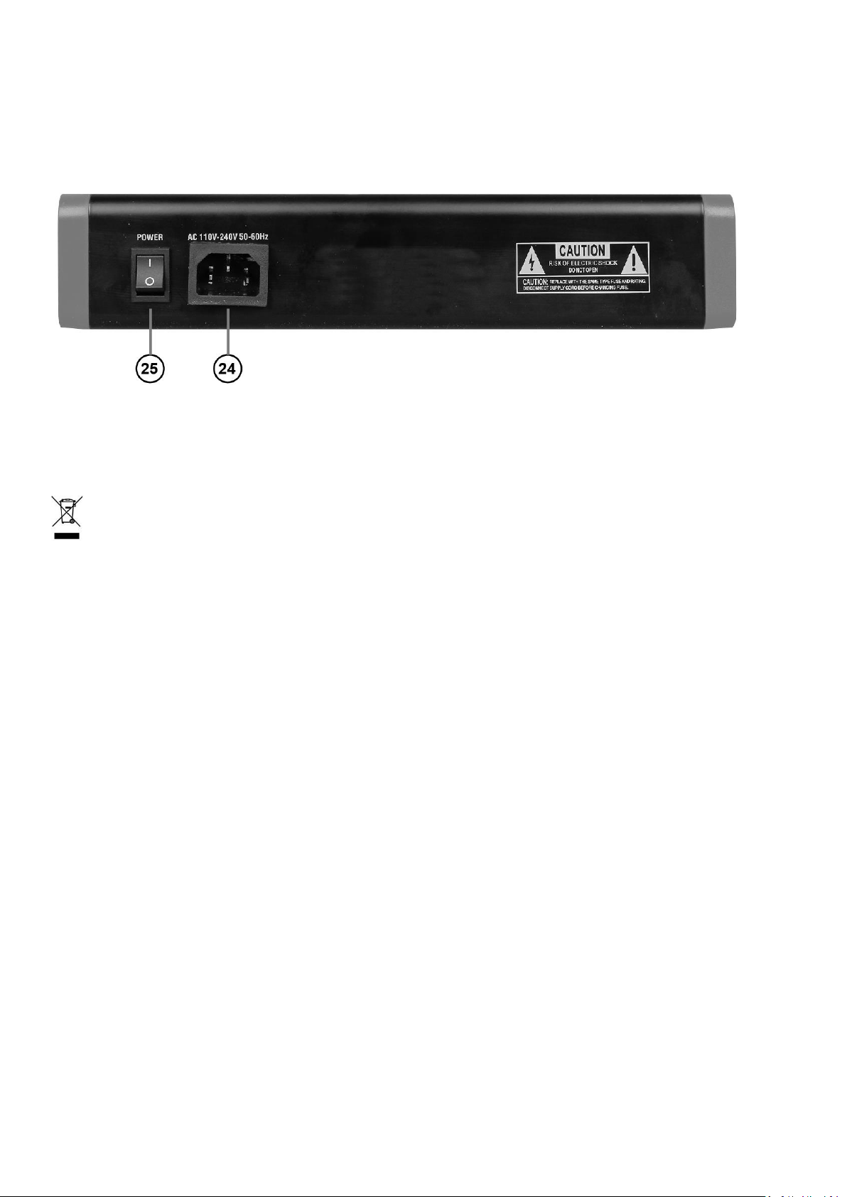
24. Power connector.
It is used to connect the power supply to the mixer via an IEC cable.
25. Power switch.
Switch it to turn on/off the power.
Information about used electrical and electronic equipment
WARNING! THE DEVICE MUST NOT BE DISPOSED OF WITH HOUSEHOLD WASTE.
This symbol indicates that this product must not be disposed of with household waste, according to the EU
and your national law. In order to prevent potential damage to the environment or health, the used product
must be recycled. In accordance with current legislation, unusable electrical and electronic devices must be
collected separately at the designated facilities for recycling, acting on the basis of applicable environmental standards.
The main goal of European and national law regulations is to reduce the amount of waste produced from used electrical
and electronic equipment, to ensure an appropriate level of collection, recovery and recycling of used equipment, and
to increase public awareness of its harmfulness to the environment, at each stage of use of electrical and electronic
equipment. Therefore, it should be pointed out that households play a key role in contributing to reuse and recovery,
including recycling of used equipment. The user of electrical and electronic equipment – intended for households –
is obliged to return it to authorized collector after its use. However, it should be remembered that products classified
as electrical or electronic equipment should be disposed of at authorized collection points.
 Loading...