

Page 1
19 A
Technical Specification:
Power Input ....................................…….DC 9V, 300 mA min.
DMX Output ................................................3 pin female XLR
MIDI Signal ........................................5 pin standard interface
Audio Input ...........................By built-in microphone or line in
Dimensions................................................... 482x132x73mm
Weight……….. ............................................................. 2.5 kg
Innovation , Quality , Performance
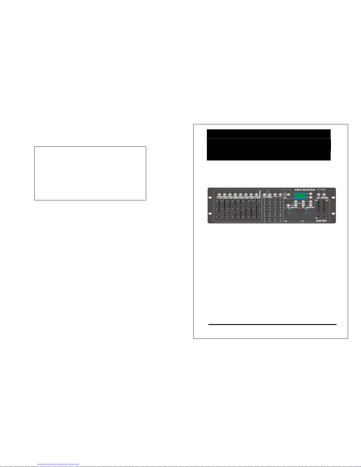
DMX MASTER
Professional Lighting Technology
CA-3216W
User Guide
Please read these instructions carefully before use
Page 2

1 A
18 A
Page 3
17 A
36
MOVEMENT 35
37
CHASE 36
38
NUMBER BUTTON1 37
39
NUMBER BOTTON2 38
40
NUMBER BOTTON3 39
41
NUMBER BOTTON4 40
42
NUMBER BUTTON 5 41
43
NUMBER BUTTON 6 42
44
NUMBER BUTTON7 43
45
NUMBER BUTTON8 44
46
NUMBER BUTTON9 45
47
NUMBER BUTTON10 46
48
NUMBER BUTTON11 47
49
NUMBER BUTTON12 48
50
NUMBER BUTTON13 49
51
NUMBER BUTTON14 50
52
NUMBER BUTTON15 51
53
NUMBER BUTTON16 52
54
RUN MODE BUTTON 53
55
UP BUTTON 54
56
DOWN BUTTON 55
57
TAP BUTTON 56
58
CLEAR BUTTON 125
59
BLACK OUT BUTTON 126
4-9 FACTORY DEFAULT
Be careful, factory reset will delete all the settings!
1. Power off the unit.
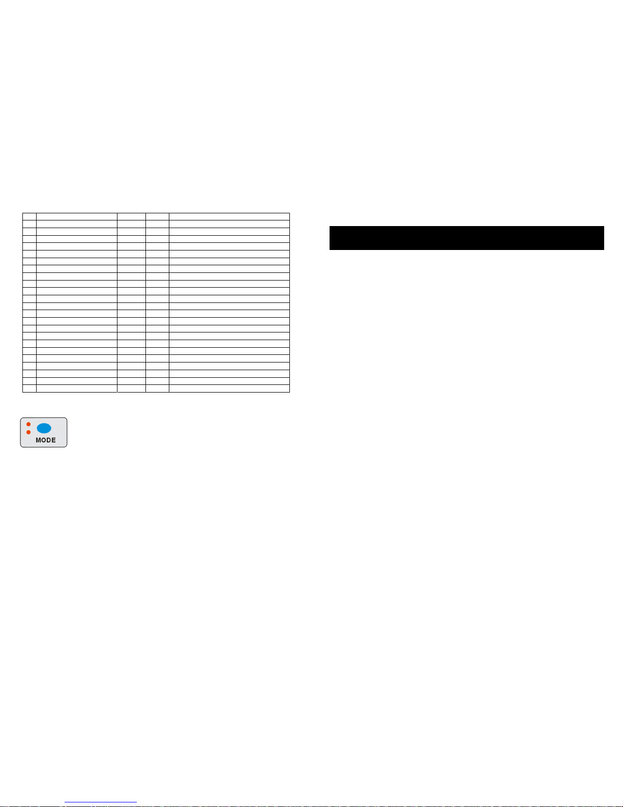
2. Hold the MODE and DEL button at the same time and then power on the unit, all the corresponding
LED indicator will flash fast for 3 times, that mean you have made the operation successfully.
2 A
CONTENTS
1. Features…………………………………………………………………………………2
Pa
g
e
2.General Instructions……………………………………………………………… ……3 Page
3.Overview……………………………………………….………………………… ……2 Page
3-1.Front View……………………………………………………………………….……4 Page
3-2. Rear View………………………………………………………………………… …4 Page
4. Operation Guide…………………………………………………………………………5 Page
4-1 Program Enable……………………………………………………………………….6 Page
4-2 Programming Scenes..………………………………………………………………6 Page
4-2.2 Scanner Copy………………………………………………………………………7 Page
4-2.3 Delete a Scene………………………………………………………………………7 Page
4-3 Programming Chase…………………………………………………………………7 Page
4-3.1 Insert a Step………………………………………………………… ………………8 Page
4-3.2 Delete a Chase……………..………………………………………………………9 Page
4-4 Assign/Reverse DMX channel……..………………………………………………9 Page
4-4.1 Assign DMX channel………………………………………………………… ……9 Page
4-4.2 Reverse DMX channel……………………………………………………………10 Page
4-4.3 Delete a scanner of DMX………………………………………………….….…10 Page
4-4.4 Display DMX channel…………………………………………………………… 11 Page
4-4.5 Auto Address………………………………………………………………………1 1
Page
4-5 Running Scenes……………………………………………………………………..12
Page
4-6 Running Movement…………………………………………………………………12
Page
4-7 Running Chases……………………………………………………………………13
Page
4-7.1 Manual Mode………………………………………………………………………13
Page
4-7.2 Auto Mode…………………………………………………………………………13
Page
4-7.3 Music Mode………………………………………………………………………14
Page
4-7.4 USB for Update/Saved/Download/Formatting …………………………………14
Page
4-8 MIDI Operation……………………………………………………………………….15
Page
4-8.1 MIDI Channel Setting………………………………………………………… 15
Page
4-9 FACTORY DEDAULT………………………………………………………………17
Page
Page 4
3 A
1. Features
A. 512 DMX channels
B. 16 fixtures of each with 32 DMX chann els
C. 32 scenes and 16 chases(Max.750 steps) programmable
D. 8 faders for manual control
E. Auto programs(scenes and chases) under control by Wait Time sliders(or Tap Sync)
and Fade Time sliders
F . Fade Time/Wait Time adjustable
G . The fixtures under control by Pan and Tilt jog wheels
H. Fine adjustment of the Pan and Tilt
I. Reverse DMX channels enable the faders to control the output reversely
J. Preview assigned or reversed DMX channels
K. Blackout and stand alone function
L. Built-in movement
M. Built-in microphone for Music triggering
N. MIDI control over scenes, chases and Blackout/Stand alone
O. LCD display
P. Auto Address
Q. USB support
2. General Instructions
Please read the user manual carefully, as it includes important informat ion regarding details of
operation, maintenance, and technical data. Keep this manual with the unit for future consult.
WARNINGS!
1 DO NOT make any inflammable liquids, water or metal objects enter the unit.
2 Should any liquid be spilled on the unit, DISCONNECT the power supply to the unit
immediately.
3 STOP using the unit immediately In the event of serious operation problems and
either contact your local dealer for a check or contact us directly.
4 DO NOT open the unit--there are no user serviceable parts inside.
5 NEVER try to repair the unit yourself. Repairs by unqualified people could cause
damage or faulty operation. Contact your nearest dealer.
CAUTIONS!
1 This unit is NOT intended for home use.
2 After having removed the packaging check that the unit is NOT damaged in any way. If
in doubt, DON'T use it and contact an authorized dealer.
3 Packaging material (plastic bags, polystyrene foam, nails, etc.) MUST NOT be left within
children's reach, as it can be dangerous.
4 This unit must only be operated by adults. DO NOT allow children to tamper or play with
16 A
MIDI IN
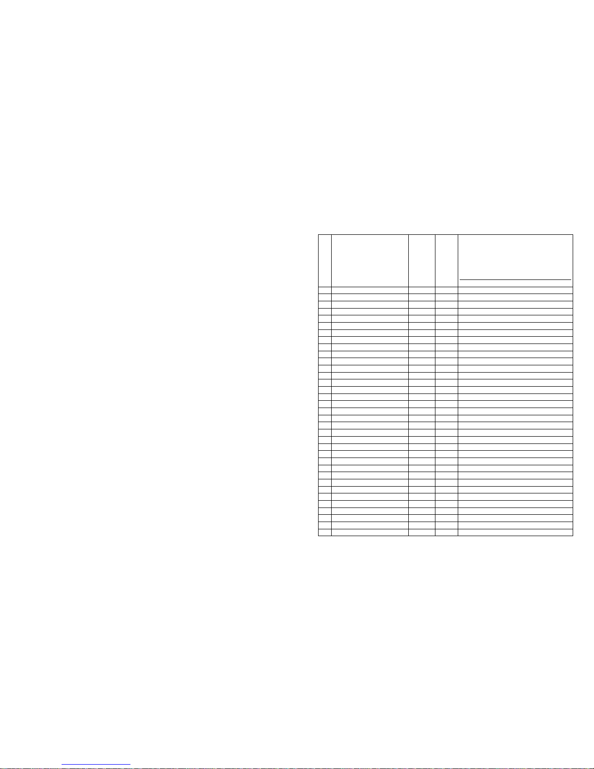
Hold MIDI IN and DOWN button at the same time to enter into MIDI IN mode. The CA-3216W is under the
control of the external MIDI signal when enter into the MIDI IN mode.
MIDI IMPLEMENTATION
Button and fade Page KK VV
FADER: 0xBn kk vv(VV=0-127)+
A: fader is from up to down:0x9n kk
001
B: fader is from dow n to up:0x9n kk
vv
FLASH:0x9n kk 127 + 0x8n kk 000
1
FADER1AND FLASH1 Page A 00 0-127
2
FADER2 AND FLASH2 Page A 01 0-127
3
FADER3 AND FLASH3 Page A 02 0-127
4
FADER4 AND FLASH4 Page A 03 0-127
5
FADER5 AND FLASH5 Page A 04 0-127
6
FADER6 AND FLASH6 Page A 05 0-127
7
FADER7 AND FLASH7 Page A 06 0-127
8
FADER8 AND FLASH8 Page A 07 0-127
9
FADER1AND FLASH1 Page B 08 0-127
10
FADER2 AND FLASH2 Page B 09 0-127
11
FADER3 AND FLASH3 Page B 10 0-127
12
FADER4 AND FLASH4 Page B 11 0-127
13
FADER5 AND FLASH5 Page B 12 0-127
14
FADER6 AND FLASH6 Page B 13 0-127
15
FADER7 AND FLASH7 Page B 14 0-127
16
FADER8 AND FLASH8 Page B 15 0-127
17
FADER1AND FLASH1 Page C 16 0-127
18
FADER2 AND FLASH2 Page C 17 0-127
19
FADER3 AND FLASH3 Page C 18 0-127
20
FADER4 AND FLASH4 Page C 19 0-127
21
FADER5 AND FLASH5 Page C 20 0-127
22
FADER6 AND FLASH6 Page C 21 0-127
23
FADER7 AND FLASH7 Page C 22 0-127
24
FADER8 AND FLASH8 Page C 23 0-127
25
FADER1AND FLASH1 Page D 24 0-127
26
FADER2 AND FLASH2 Page D 25 0-127
27
FADER3 AND FLASH3 Page D 26 0-127
28
FADER4 AND FLASH4 Page D 27 0-127
29
FADER5 AND FLASH5 Page D 28 0-127
30
FADER6 AND FLASH6 Page D 29 0-127
31
FADER7 AND FLASH7 Page D 30 0-127
32
FADER8 AND FLASH8 Page D 31 0-127
33
FADE TIME FADER 32 0-127
34
WAIT TIME FADER 33 0-127
35
FIXTURE SCENE 34
Page 5
15 A
Before you do the below operation, you should insert the USB memory to the unit first.
UPDATE
Power off the unit, hold PROGRAM/REC, MODE and DOWN these three buttons at the same time, then
power on the unit, after 3 seconds, the word “write success” will show on the LCD display, then you can
release the button and restart the unit, the unit has been updated successfully.
Download
Hold MODE and UP button at the same time, the LCD will show the words “Saving Files” on the display.
Then you press any of the chase buttons or scenes button which the LED indicator is not bright, all the files
stored in the button will save in the USB memory now. Please note that if the LED indicator button 1-16
light up, that means there is file in the USB memory, if you press the bright button, the before file will be
replaced. You should choose the button which the LED indicator is not bright. It will save in the filename of
“CA-3216W” (before use, you should create one file called “CA-3216W”, or you cannot save successfully)
Upload
Hold MODE and DOWN button at the same time, you can press any button of the scenes and chase button
which the LED indicator is not bright, then the file in your USB memory will upload to the button you
pressed. The LED indicator of the scenes and chases light up means there are scenes or chase stored in it.
If you still press it, the previous one will be replaced by the upload one.
U Disk Formatting
Switching off controller and connecting U disk to controller’s USB interface. And then, keep pressing
controller’s MODE + RELEASE/CLEAR button + 16 button around 3 seconds, meanwhile, switching on the
controller. It will show the status and prompts of U disk formatting in the LCD display. It will also shows
prompts if the whole process of formatting was finished successfully.
Attention please:
1. You can format U disk via controller if the U disk cannot be recognized which is you cannot upload or
download files to U disk.
2. It needs take time to do formatting. The more high capacity of U disk, the more time spent for formatting.
For example, it needs to take around 150 seconds for 8GB U disk.
3. You are supposed to rerun procedure by following above mentioned process of formatting if it shows
abnormal or controller prompts format error.
4-8 MIDI Operation
4-8.1 MIDI Channel Setting
MIDI SET
Hold TAP/MIDI/CH and MIDI IN buttons at the same time for 3 seconds to enter into MIDI channel setting.
4 A
it.
5 NEVER use the unit under the following conditions:
In places subject to excessive humidity.
In places subject to vibrations or bumps.
In places with a temperature of over 45 C/113 F or less than 2 C/35.6 F.
Protect the unit from excessive dryness or humidity (ideal conditions are between
35% and 80%).
1 DO NOT dismantle or modify the unit.
3. Overview
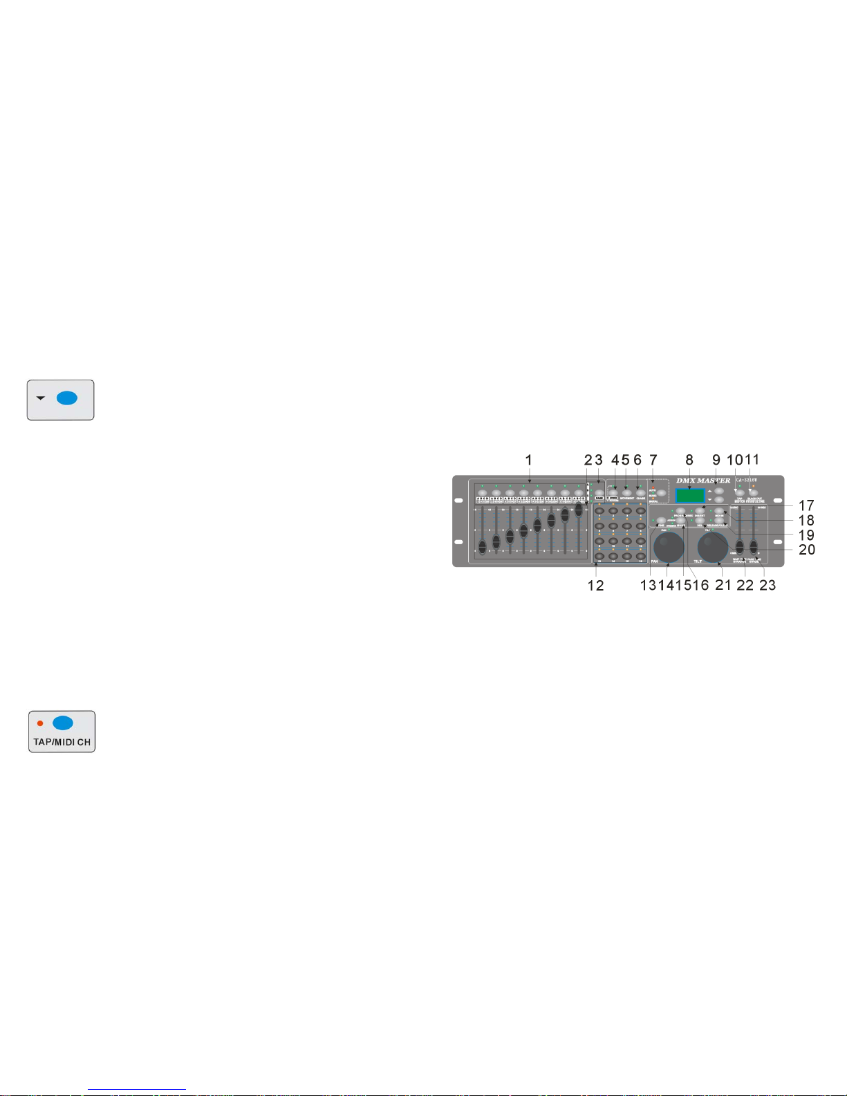
3-1. Front View
CA-3216W
1. Scene Buttons (1-8) Load or store scenes. There are a maximum of 32 programmable scenes
2. Faders These faders are used to control the intensity of all the channels
3. PAGE Select Button Used to select page between Page A (1-8), Page B (9-16) , Page C (17-24),
Page D (25-32).
4. FIXTURE/SCENE Buttons Press the fixture/scene buttons to enter into scene mode
5. MOVEMENT Button 16 Built-in movement for your convenient use
6. CHASE Button Press the CHASE button to enter into Chase mode.
7. AUTO/MUSIC/MANUAL When running the chase, press the button to change the running mode
8. LCD Display Shows the current activity or programming state.
9. Up/Down Buttons Press Up/Down button to select chases or adjust the sound sensitivity of
audio control
10. TAP/MIDI CH Change the rhythm of chases or set Midi address
11. Blackout/Stand alone Button Tap to momentarily pause whole output. Hold on this button enter Stand
alone
12. CHASE Button (1-16) Running Chase or select fixtures/scanners
13. FINE Button When Fine is on, the Pan or Tilt wheel will control the scanner in the smallest
increment.
14. PAN Wheel This jog wheel is used to control the pan of the scanner or for programming.
15. MODE Button Pressing Fine and Mode buttons to activate Assign
Page 6
5 A
16. PROGRAM/REC Button Activates Program mode or Record scenes/chases
17. Insert Button Add a step to a chase
18. MIDI IN Receive MIDI signal
19. RELEASE/CLEAR Clear out the output for faders or clear all the outputs or Reverse mode
20. Del Delete scenes or chases.
21. TILT Wheel This jog wheel is used to control the Tilt of the scanner or for programming.
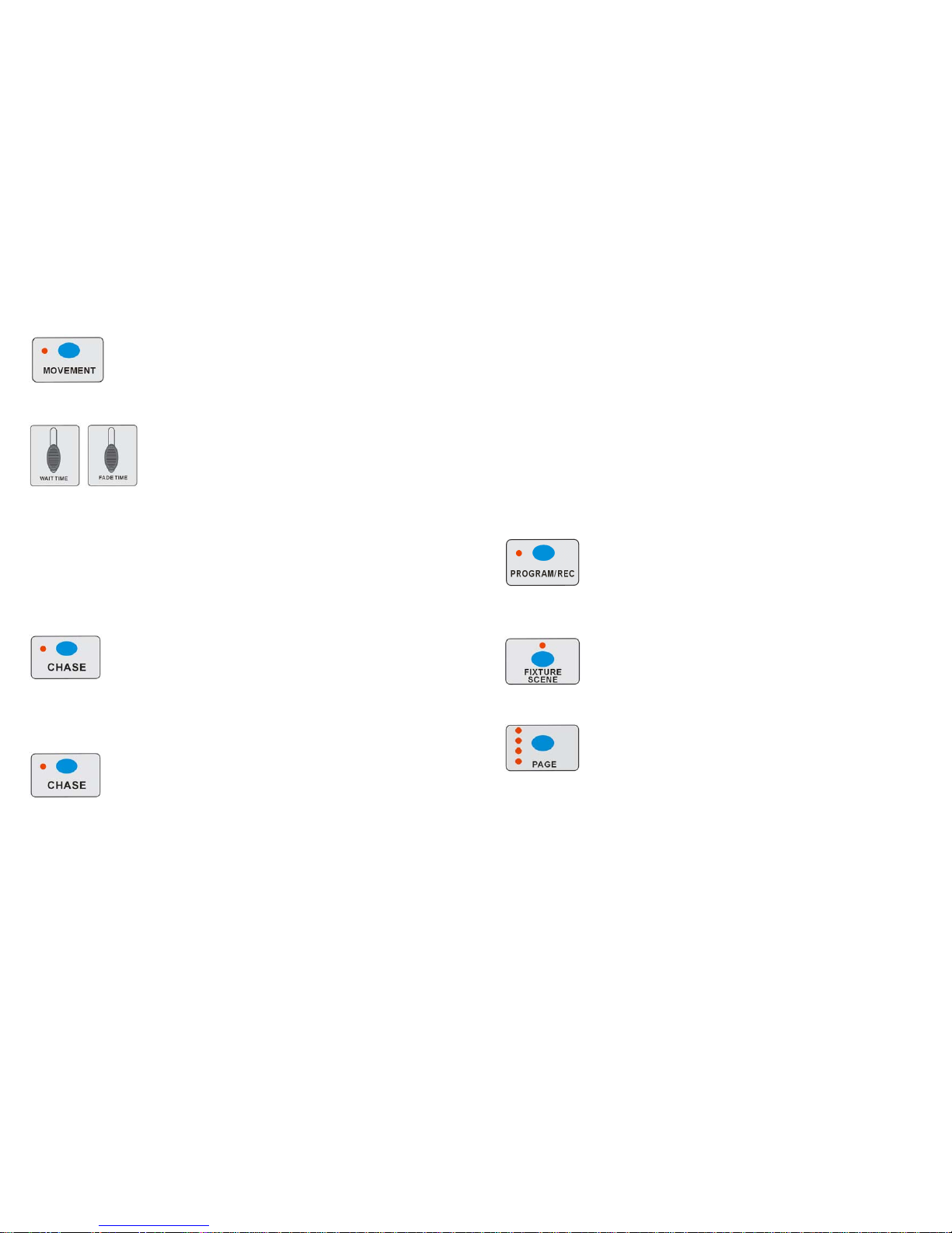
22. WAIT TIME Slider Used to adjust the chase wait time within th e range of 0.1 second to 5
minutes.
23. FADE TIME Slider Used to adjust the fade time.
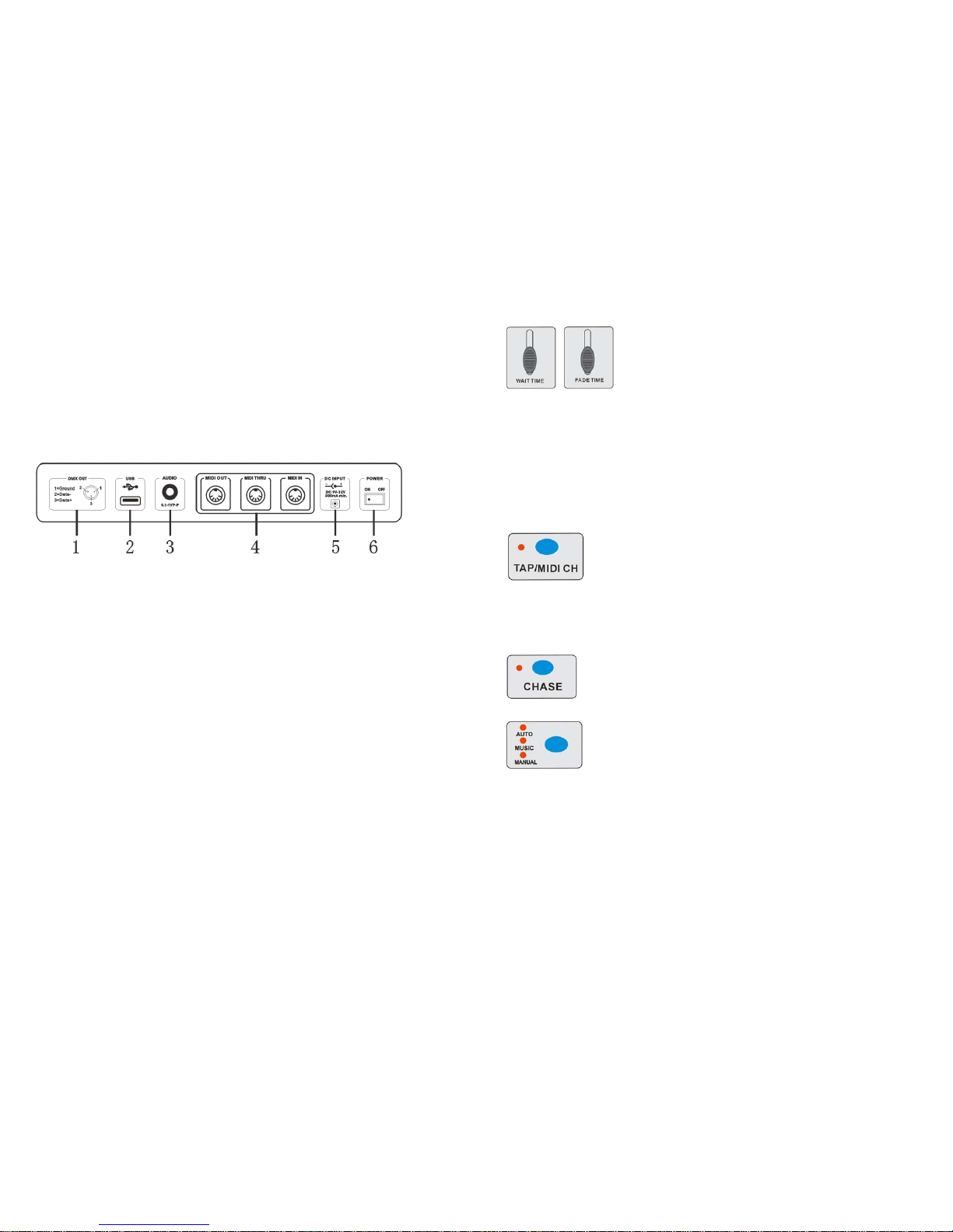
3-2 Rear View
1. DMX Out This connector sends your DMX value to the DMX scanner or DMX
pack.
2. USB PORT Connect to the computer when upgrading the firmware
3. AUDIO IN 0.1V~1Vp-p.
4. MIDI OUT/THRU/IN Send/Receive MIDI signal
5. DC Input DC 9 -12V, 300mA min.
6. Power Switch This switch turns On/Off the power.
4. Operation Guide
General
This unit allows you to program 16 fixtures of 32 DMX channels (512CH), 32 programmable
scenes and 16 chases of max.750 st eps, using 8 faders and ot her function butt ons. With the use
of two jog wheels, you may easily co ntrol t he Pan or Tilt of the fixt ures. To tailor your special effect
lighting, this unit enables you to Assign or Reverse the DMX channe ls, or set the DMX address
automatically. In addition, two units can set up communication through the MIDI. You can
download/upload the data by U-Disk for the instant use.
Display Information
The LCD Display contains a maximum of 2x8 characters.
LCD Display Message
Fixture Select Selecting the fixture to control
Movement Select Selecting the movement
Chase Select selecting the chase
Chase 5 Chase 5 is activated.
14 A
2. Press the chase button1-16 to select the chases that you want to run. The LED indicator of the selected
ones will light up.
3. Tap the Auto/Music/Manual button to activate Auto mode. The Auto LED lights indicating Auto mode is
active.
4. After selecting chases you wish to run, you can use the Wait Time slider (or press TAP/MIDI CH button)
and Fade Time slider to adjust the chase to your desired effect.
Hints:
The TAP/MIDI CH button is used to set the speed by tapping the button several
times, the last two taps will define the speed with a maximum of 5 minutes.
TAP/MIDI CH will override any previous setting of the Wait Time slider unless the slider
is moved again.
4-7.3 Music Mode
1. Press the CHASE button to enter into the CHASE Mode.
2. Press the chase button1-16 to select the chases that you want to run.
3. Tap the Auto/Music/Manual button to activate Music mode. The Music LED lights indicating Music mode
is active
4. You can adjust the sensitivity by pressing UP/DOWN button.
5. The chases you've selected will chase in a sequential order according to the music rhythms detected by
the built-in microphone.
4-7.4 USB for Update/Saved/Download/Formatting
Page 7
13 A
Before running the MOVEMENT, you should setting the Assign/Reverse DMX channels first.
You can also run the MOVEMENT, pressing 1-16 to select the built-in movement:
1. Press the fixtures you would like to run the movement, then press MOVEMENT button to select the
movement, turn the PAN/TILT to adjust the fixtures to the right place.
2. Move the FADE TIME fader to adjust the range of the pattern, or move the WAIT TIME to adjust the
speed of the PAN/TILT.
Note: when adjust the movement of PAN/TILT, please do not use faders to change the position of
PAN/TILT, otherwise, the position cannot be controlled by the PAN/TILT wheels.
4-7 Running Chases
Manual mode/Auto Mode/Music Mode will be available when running chases.
4-7.1 Manual Mode
1. Press the CHASE button to enter into the chase mode.
2. You can open it by press the button directly. After you open it, the LED indicator will light up, if there is
no any CHASE store in it, it will show “NULL” on the LCD display.
3. You can use the UP/DOWN button to run the CHASE manually.
4-7.2 Auto Mode
This function allows you to run programmed chases in a sequential loop.
1. Press the CHASE button to enter into Auto Mode.
6 A
Step 002 The 2nd step of a chase
Data 151 DMX value(000-255)
WT: 1M36S The current Wait Time is 1 minute and 36 seconds
TP: 5.32S The time of the last two taps is 5.32 seconds
FT: 10.5S Fade Time is 10.5 seconds
ASS 07 08 Assign DMX channels 7 and 8
RES 10 13 Reverse DMX Channels 10 and 13
SN 6 Scene 6
4-1 Program Enable
When the power is turned on, the firmware version will show on the LCD display for 1 second,
then this unit will enter Manual mode automatically. Pr ess the PROGRAM/RE C button for 3
seconds to activate Program mode, the LED indicator near to this button flashes slowly indicating
Program in active.
4-2 .1Programming Scenes
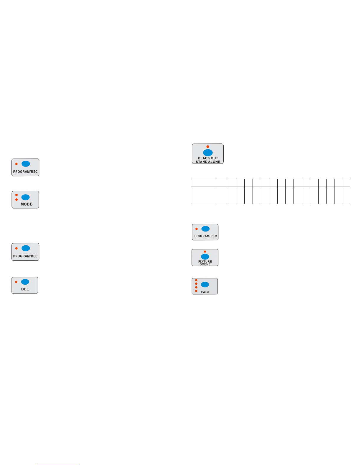
1. Hold PROGRAM/REC button for 3 seconds to enter program mode.
2. Press the FIXTURE/SCENE button, the LED indicator above it will light up but not flash. Then select the
fixtures you want to program.
3. Move the faders to select your desired dimmer intensity if you are using a dimmer
.
You can also use the two jog wheels to control the Pan or Tilt movement of the scanner.
4. Press FIXTURE/SCENE button, when the LED indicator above it flashing, the fixture which you choose
will quench out.
5. Tap PAGE button to select the page you want to store your scene into. There are total 4 pages (A, B, C,D)
you can select. The button1-8 light up means there has scene stored in it, if you press it again, the
before scene will be replaced.
6. Click the PROGRAM/REC button, then press the button1-8, all the LED indicator will flash fast for 3
times, that means you have store the scene successfully.
7. Repeat steps 2-6 until all desired scenes have been programmed into memory.
8. After you finish your programming, hold PROGRAM/REC button for three seconds to exit Program mode,
the LED goes out indicating this selection.
Page 8
7 A
Note: After finishing the current programming operation, you can hold RELEASE/CLEAR button to
clear all the output before next step operation.
4-2.2 Scanner Copy
This function allows you to copy the settings of one scanner to another.
1. Press PROGRAM/REC button to enter program mode.
2. Press the fixture(scanner) button you want to copy
3. Hold the MODE button, tap the Fixture (Scanner) button you want to copy to. The corresponding LED
indicators will flash three times fast. Then the copy is successful.
Note: After finishing the current programming operation, you can hold RELEASE/CLEAR button to
clear all the output before next step operation.
4-2.3 Delete a Scene
1.Press PROGRAM/REC button to enter program mode.
2. Press the FIXTURE/SCENE button, then the LED indicator above it will flash.
3. Press PAGE button to select page that the scene which you desire to delete is in.
4.
5.Hold the DEL button and the Scene button to delete the scene that you’ve stored (When selecting the
page, the related LED indicators will show you whether there is a scene stored). The LED indicators on the
panel will flash three times fast, which means delete the scene successfully.
Note: After finishing the current programming operation, you can hold RELEASE/CLEAR button to
clear all the output before next step operation.
4-3 Programming Chase
This function will allow you to store up to 750 steps into one chase (The max. steps is 750 for the whole
12 A
2. Hold BLACK OUT button for 3 seconds till the BLACK OUT /STAND ALONE button light up.
3. Hold down the fixture 1 button and then press for 3 seconds to enter Stand-Alone mode. The LCD
display will show “STAND ALONE” on it.
4. You can use the UP/DOWN button to choose the fixture which you want to address. That will show on
the LCD display.
3. The DMX address of the fixtures will be set automatically after you choose the fixture and press the 1-16
button to match the
Fixture No. 1 2 3 4 5 6 7 8 9 10 11 12 13 14 15 16
DMX Address For
Press
Fixture 1~16
button
1 33 65 97 129 161 193 225 257 289 321 353 385 417 449 481
Note: After finishing the current programming operation, you can hold RELEASE/CLEAR button to
clear all the output before next step operation.
4-5 Running Scenes
1. Press the FIXTURE/SCENE button to enter scene mode (The related LED indicator will be flashing)
2.The scene button1-8 light up means there is scene stored in it. You can open the scene by press them
directly or by the faders.
3.You can choose the page which your scene stored in by press PAGE button.
Note: After finishing the current programming operation, you can hold RELEASE/CLEAR button to
clear all the output before next step operation.
4-6 Running Movement
Page 9
11 A
4-4.3 Delete a fixture of DMX channels
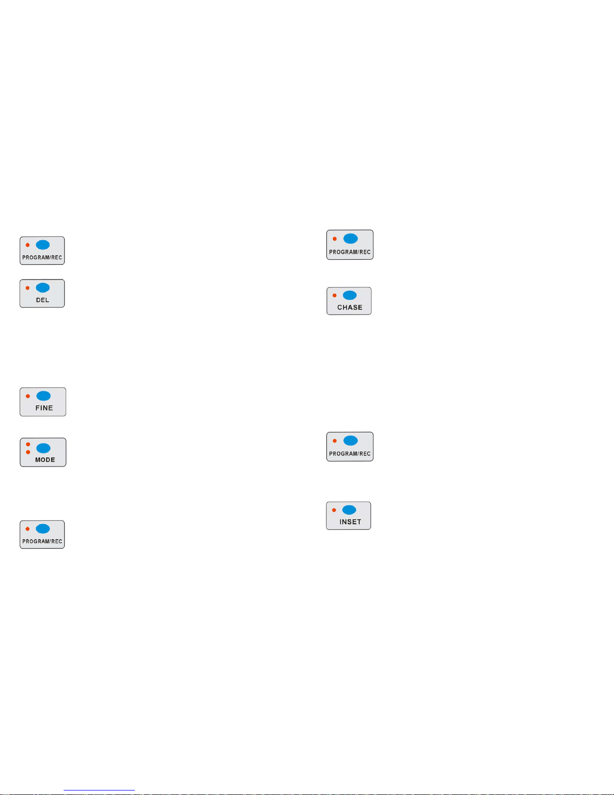
1. Press PROGRAM/REC button to enter program mode.
2. Hold the FINE and MODE button at the same time till to enter into Assign or Reverse mode
3. Tap the fixture1-16 to select the fixture you wish to delete.
4. Press the DEL and MODE buttons at a time, all LEDS should flash three times briefly; indicating the
DMX channels of the fixture (scanner) is all deleted.
Note: After finishing the current programming operation, you can hold RELEASE/CLEAR button to
clear all the output before next step operation.
4-4.4 Display DMX channel
1. Press PROGRAM/REC button to enter program mode
2. Press the FINE and MODE buttons at a time, the Assign LED lights.
3. Press the FINE and MODE buttons a second time, the Assign LED goes out and the Inversion LED
lights.
4. Tap the fixture button that holds the Pan and Tilt channel, the LCD shows the Pan and Tilt.
4-4.5 Auto Address
1. Press PROGRAM/REC button for 3 seconds to enter program mode.
8 A
set).
1. Press PROGRAM/REC button to enter program mode.
2. Press the CHASE button to enter chase programming mode, the LED indicator above it will light up.
The fixture1-16 flashing, that means there is chase stored in it, then press the 1-16 chase buttons, all
the Led indicator will quench out.
3. Then press the No button 1-16 to select the fixture you want to program. Push the fader to get your
desired effect.
4. Tap the PROGRAM/REC button to store, the related LED indicators will flash three times, which means
one step has stored successfully.
5. If you want to change the chase, you can press the CHASE button again, then the LED indicator of the
chase you have stored will flash, the one just light up but not flash means that is the current selection.
You can press any chase button to program the chase you like. Then the Chase and step will show on
the LCD display.
6. Repeat steps 2-5 until you've reached your desired chase effect.
You may record up to 750 steps into a chase.
7. Hold PROGRAM/REC button 3 seconds to exit the program mode.
Note: After finishing the current programming operation, you can hold RELEASE/CLEAR button to
clear all the output before next step operation.
4-3.1 Insert a Step
1. Press PROGRAM/REC button to enter program mode.
2. Press chase button, the LED indicator will light up, and the fixture 2 will flash. Then hold the fixture 2
button for 2 seconds, the fixture 2 and chase LED indicator will quench out, and the FIXTURE/SCENE
button LED indicator will light up.
3. Press the INSERT button, the LED indicator near it will light up.
4. Press the No. button 1-16 to select the fixture and then push the fader to get your desired effect.
5. Use the UP/DOWN button to choose the step which you want to insert to. That will show on the LCD
display.
6. Press PROGRAM/REC to store the scene inserted. The related LED indicators will flash three times.
Page 10
9 A
That means you have stored the operation successfully.
Note: After finishing the current programming operation, you can hold RELEASE/CLEAR button to
clear all the output before next step operation.
4-3.2 Delete a Chase
1. Press PROGRAM/REC button to enter program mode.
2. Hold DEL button, then tap the CHASE button which you want to delete; all related LED indicators will
flash three times briefly indicating this chase has been deleted.
Note: After finishing the current programming operation, you can hold RELEASE/CLEAR button to
clear all the output before next step operation.
4-4 Assign/Reverse DMX channel
4-4.1 Assign DMX channel
1. Press PROGRAM/REC button to enter program mode.
2. Press button1-16 to select the fixture.
3. Press the FINE and MODE buttons at a time, the Assign LED lights up indicating Assign mode is active.
4. Use Up and Down button to change between the PAN and TILT, the corresponding LED lights indicating
this selection.
10 A
5. Tap the PAGE Select button to select Page A or Page B or Page C or Page D.
6. Holding the MODE button, tap the Scene button1-8, all LED should flash briefly indicating the DMX
channel is assigned.( Scene button 1 stands for DMX channel 1, Scene button 2 stands for DMX
channel 2, and so on.)
7. Continue steps 2-6, you may assign 16 fixtures for the PAN/ TILT movements. Under ASSIGN MODE,
PAN / TILT can be set both in page A and page B and page C and page D.
Note: After finishing the current programming operation, you can hold RELEASE/CLEAR button to clear all
the output before next operation.
4-4.2 Reverse DMX channel
1. Press PROGRAM/REC button to enter program mode.
2. Press button1-16 to select the fixture.
3. Press the FINE and MODE buttons at a time for two times till to the REVERSE LED lights up indicating
reverse mode is active.
4. Use Up and Down button to change between the PAN and TILT, the corresponding LED lights indicating
this selection.
5. Tap the PAGE Select button to select Page A or Page B or Page C or page D.
6. Holding the MODE button, tap the Scene button1-8, all LED should flash briefly indicating the DMX
channel is reversed.( Scene button 1 stands for DMX channel 1, Scene button 2 stands for DMX
channel 2, and so on.)
7. Continue steps 2-6, you may assign 16 fixtures for the PAN/ TILT movements. Under ASSIGN MODE,
PAN / TILT can be set both in page A and page B and page C and page D.
Note: After finishing the current programming operation, you can hold RELEASE/CLEAR button to
clear all the output before next step operation.
 Loading...