

Page 1
DMX Standard Wall Switch Controller User Guide
DSC5
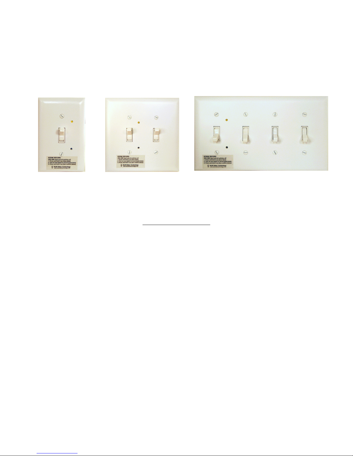
1-4 Gang Options
DSC5 OVERVIEW
The DSC5V DMX controller uses a standard wall switch available with 1 - 4 switch(es) to
control a standard DMX lighting systems. Store up to 4 static scenes and then recall just by turning
on the respective switch. Easily turn on DMX controlled lights without having to turn on or use a
DMX lighting board or controller. For example switch 1 could be "Band Practice", switch 2 "Stage
Lights", switch 3 "Audience Lights", switch 4 "Balcony". Simply turn on any of the switches and the
pre recorded scene will turn on the DMX lights, with an optional 5 second fade. If the "Merge"
function is turned off then any DMX input will override the switches and take control allowing a
DMX controller to control the lights. Turn off the DMX controller and the switches again are
operable. The switch/scenes are HTP (highest takes precedence) merged with each other allowing
any or all switches to turn on it's respective scene. DMX scenes are easily recorded to any of the
switches from the front of the unit.
Record up to 4 DMX scenes
Optional 5 second fade up/down
Optional Merge/Override DMX input function
Page 2

ELM Video
Technology
DSC5 - DMX Standard Wall Switch Controller User Guide
Pg 2
CONNECTION
There are several ways the unit can be installed. Example 1 shows the unit installed as the final device before
the data is sent to the DMX dimmers and fixtures. In this configuration the final DMX signal that feeds the dimmers
and/or lights, loops through the DSC5 wall switch unit, allowing the switches to control the dimmers and/or lights.
Example 2 (see EXAMPLE 2 below) shows the unit installed as part of the DMX source by merging the DSC5 units’
DMX with any other DMX generating device(s). In this configuration the DSC5 generates a DMX signal and then is
merged with several merge options using our DMG Merger products.
In either configuration, once the DSC5 wall switch unit has the scenes recorded, the DMX input could be
removed and the unit simply generates a DMX signal to control the dimmers and/or lights in a standalone DMX
controller.
EXAMPLE 1
1, 2, 3, or 4
Gang/Switch
Record Scene Button
Cable or Wire
Status & Record
Scene Indicator LED
Very soft brightness for
undisturbed performances
DMX to Switch
Installed as needed:
DMX to Switch, Power, and
DMX from switch
- 400' or more depending on cable
- Belden 1420A or equivalent
User DMX Lighting Console or
any DMX Generating Device
9V
Power
Supply
+9VDC
DMX OUTPUT: To
DMX from Switch
3 Pairs needed:
(1) DMX Input Pair (optional
for normal operation)
(1) +9VDC Power Wire
(1) DMX Output Pair
Recommended Wire:
24 - 22 AWG or larger
shielded with twisted pairs
INSTALLATION PRECAUTIONS:
DO NOT connect 120V to any of the switches or
the circuit board.
DO NOT connect 120V to any pairs of the data
input/output cable/wire.
DMX Dimmers,
Fixtures, etc.
1, 2, 3, or 4 Switch Options
www.elmvideotechnology.com
copyright © 2017 ELM Video Technology, Inc.
DMX data length is limited to 3000' depending on
type of wire used.
Depending on type of wire used ensure there is a
minimum of 8VDC present at the PCB with the unit
powered.
Switch wiring gang boxes, and installation,
are user (or electrician) required
DSC5-dmx-standard-wall-switch-controller-user-guide.lwp
Page 3

ELM Video
Technology
EXAMPLE 2
1, 2, 3, or 4
Gang/Switch
DSC5 - DMX Standard Wall Switch Controller User Guide
DMX Merger
See ELM Video Technology’s
line of DMX Merger products.
Multiple merge options
available.
Cable or Wire
Status & Record
Scene Indicator LED
Very soft brightness for
undisturbed performances
Installed as needed:
DMX to Switch
recorded)
(Optional once scenes are
, Power, and DMX from switch
- 400' or more depending on cable
- Belden 1420A or equivalent
User DMX Lighting Console or
any DMX Generating Device
DMX Source(s)
9V
Power
Supply
DMX
Merger
+9VDC
DMX from DSC5V Wall Switch
DMX OUTPUT: To
DMX Dimmers,
Fixtures, etc.
Pg 3
Record Scene Button
1, 2, 3, or 4 Switch Options
PCB WIRING DIAGRAM:
DIP SWITCH SETTINGS
Reset Power to Activate
1: - TRANSITION / FADE RATE
ON - 5 SECONDS
OFF - IMMEDIATE
2: - DMX LOSS DIRECTIVE
OFF - Transition/fade to switch/scene(s)
ON - DMX output is turned off
3: - OVERRIDE / MERGE
OFF - DMX Input will OVERRIDE all switches
ON - DMX will MERGE with enabled switches
4: Unused
3 Pairs needed:
(1) DMX Input Pair (optional
for normal operation)
(1) +9VDC Power Wire
(1) DMX Output Pair
Recommended Wire:
24 - 22 AWG or larger
shielded with twisted pairs
INSTALLATION PRECAUTIONS:
DO NOT connect 120V to any of the switches or
the circuit board.
DO NOT connect 120V to any pairs of the data
input/output cable/wire.
DMX data length is limited to 3000' depending on
type of wire used.
Depending on type of wire used ensure there is a
minimum of 8VDC present at the PCB with the unit
powered.
Switch wiring gang boxes, and installation,
are user (or electrician) required
DMX Out to Dimmers and Fixtures + pin 3
DMX Out to Dimmers and Fixtures – pin 2
DMX Out to Dimmers and Fixtures Shield/Drain
DMX From House Controller + pin 3
DMX From House Controller – pin 2
Optional – Only needed if DMX loop through to
merge or override is desired, or to record a scene
Factory Wired
Power Supply Positive +9VDC
Power Supply Ground
SCENE RECORD
With DMX Input and all switches off
1. Press and hold 3 sec [slow blink]
2. Turn on one switch to record [rapid blink]
3. Press and hold 3 sec [two confirm blinks]
WIRE EXAMPLE USING CAT5 COLOR CODE
CONNECTIONWIRE
DMX - to SwitchWhite/Blue
DMX + to SwitchBlue/White
+5V to SwitchWhite/Orange
Power Supply Gnd to SwitchOrange/White
DMX - from SwitchWhite/Green
DMX + from SwitchGreen/White
www.elmvideotechnology.com
copyright © 2017 ELM Video Technology, Inc.
Switch GndShield
DSC5-dmx-standard-wall-switch-controller-user-guide.lwp
Page 4

ELM Video
Technology
DSC5 - DMX Standard Wall Switch Controller User Guide
Pg 4
Install the appropriate DMX and power wires. Insure the path is safe and away from the public and not prone to
damage as these wires carry the DMX signals and power to/from the unit for the lighting system. It is recommended to
install inside a conduit. Connect the DMX generating device, power supply, and DMX output wires source to the
installed wires, check for accuracy, check the polarity of the power supply on both ends before applying power. Turn
the unit on and check for that the power LED is illuminated. Send DMX data, the data LED should be illuminated.
Record scenes as needed and check for proper operation.
DO NOT CONNECT 120VAC TO ANY OF THE CONNECTIONS OF THIS UNIT.
Connect DMX source wires (lighting board or similar) into the input screw terminals labeled: -2 and +3 (XLR
connector pins 2 and 3 respectively) See PCB Wiring Diagram, and WIRE Example. The input is terminated locally so
loop thru is not recommended. Connect the DMX output destination wires to the screw terminals labeled: Gnd, -2, and
+3. Connect the power supply to positive and ground wires to the PWR in terminals - CHECK POLARITY BEFORE
CONNECTING, REVERSE OR OVER VOLTAGE MAY DAMAGE THE UNIT. Once connected the power LED will
illuminate indicating power is present. Under normal operating conditions and all DMX input and outputs connected,
check the voltage at the PCB and insure that it’s in the range of 8VDC to 12VDC. This is important to insure proper
operation.
PCB DIP SWITCH SETTINGS
Set the dip switches for the desired operation and RESET POWER to activate the new settings.
To access the dip switches, remove the front cover to reveal the PCB.
ON
OFF
ON
OFF
Dip Switch 2 ON - If the DMX input is lost then the DMX output is turned off
ON
OFF
Dip Switch 3 OFF - DMX Input will OVERRIDE all switches
Dip Switch 3 ON - DMX will MERGE with enabled switches
ON
OFF
D.S. 1: - TRANSITION / FADE RATE - Sets the transition rate for switch/scene setting changes. If a respective scene/switch
is turned on or off the scene recall will either be immediate or have a 5 second transition rate.
1
Dip Switch 1 OFF - Transition/fade rate = IMMEDIATE
Dip Switch 1 ON - Transition/fade rate = 5 SECONDS
D.S. 2 - DMX LOSS DIRECTIVE - If DMX is lost or no DMX is present on the input this setting determines the state of the
DMX output of the DSC5 wall unit. NOTE: If ON then the switch outputs will not be sent unless there is DMX present on the
2
input and the unit is in the MERGE mode. Otherwise once the DMX input signal is lost the output will turn off.
Dip Switch 2 OFF - The DMX output is always on/active
D.S. 3: - OVERRIDE SCENE(s) or MERGE/COMBINE w ith DMX INPUT - IF DIP SWITCH 3 IS OFF = [OVERRIDE] setting,
all enabled scene(s) will only be active IF there is not a DMX input signal present, (either turning off the DMX lighting board or
3
disconnecting or unplugging the DMX input). IF DIP SWITCH 3 IS ON = [MERGE] - The DSC5 wall unit will merge/combine all
enabled scene(s) with incoming DMX. NOTE Dip Switch 2 must be OFF for this setting to be active.
D.S. 4: - Aux (Future Use)
4
Plan all DMX changes carefully, understand how each mode will react, and thoroughly test each device after any configuration cha nges.
To abort any settings while in the programming mode, toggle the power to reset the unit, and reenter if desired.
www.elmvideotechnology.com
copyright © 2017 ELM Video Technology, Inc.
DSC5-dmx-standard-wall-switch-controller-user-guide.lwp
Page 5

ELM Video
Technology
DSC5 - DMX Standard Wall Switch Controller User Guide
Pg 5
LED BLINK RATES
DescriptionRate
No DMX is being receivedOFF
Valid DMX is being receivedON
1x
2x Blink
3x Flicker
DMX Input data error has occurred since
powered OR unit is in Record Scene Mode
Record Scene Mode with the selected switch
to be recorded turn on
Respective scene has been recorded2 Flashes
Record Scene Error, button is pressed with a
switch on OR no DMX is present
SCENE RECORDING
1.
Insure a valid DMX signal is present indicated by the DMX input LED on.
2.
Preset a desired scene from the DMX lighting board or DMX generating device.
3.
Enter the PGM Scene Record Mode by press and holding the Record button for 3 seconds, the data LED will blink
at the 1x rate. Turn on only 1 switch that the scene is to be recorded to, the data LED will blink at the 2x rate. Press and
hold the record button for 3 seconds, the data LED will flash 2 times indicating the scene has been recorded. To abort
recording, wait 20-30 seconds to allow the unit to time out.
Repeat steps to record each scene.
While in the scene record mode inactivity for 30 seconds will automatically cancel and exit.
www.elmvideotechnology.com
copyright © 2017 ELM Video Technology, Inc.
DSC5-dmx-standard-wall-switch-controller-user-guide.lwp
Page 6

ELM Video
Technology
DSC5 - DMX Standard Wall Switch Controller User Guide
Pg 6
SPECIFICATIONS
DMX CONTROL WARNING:
NEVER use DMX data devices where human safety must be maintained
NEVER use DMX data devices for pyrotechnics or similar controls
Manufacturer: ELM Video Technology
Model: DSC5V
Name: DMX Standard Wall Switch Controller
MPN: DSC5V-1G (2G, 3G, or 4G)
Dimensions: 1 Gang - 4.75"H x 3"W x 2"D, 4 Gang 4.75"H x 8.4"W x 2"D
Switch Input(s): +5VDC Maximum
DATA TYPE: DMX (250Khz)
DATA INPUT: DMX - (Shield) Not connected, Pin 2 Data - , Pin 3 Data +
DATA OUTPUT: DMX outputs - Pin 1 - (Shield) Power supply common, Pin 2 Data -, Pin
3 Data +
Weight: .75 pounds
POWER INPUT: +9VDC (7.5V minimum at circuit board input)
Current: 125mA
Internal FUSE: 500mA PCB SMT
External Power Supply: +9VDC wall mount
Voltage Input: 100 ~ 240 VAC 50/60hz
www.elmvideotechnology.com
copyright © 2017 ELM Video Technology, Inc.
DSC5-dmx-standard-wall-switch-controller-user-guide.lwp
 Loading...