

Page 1
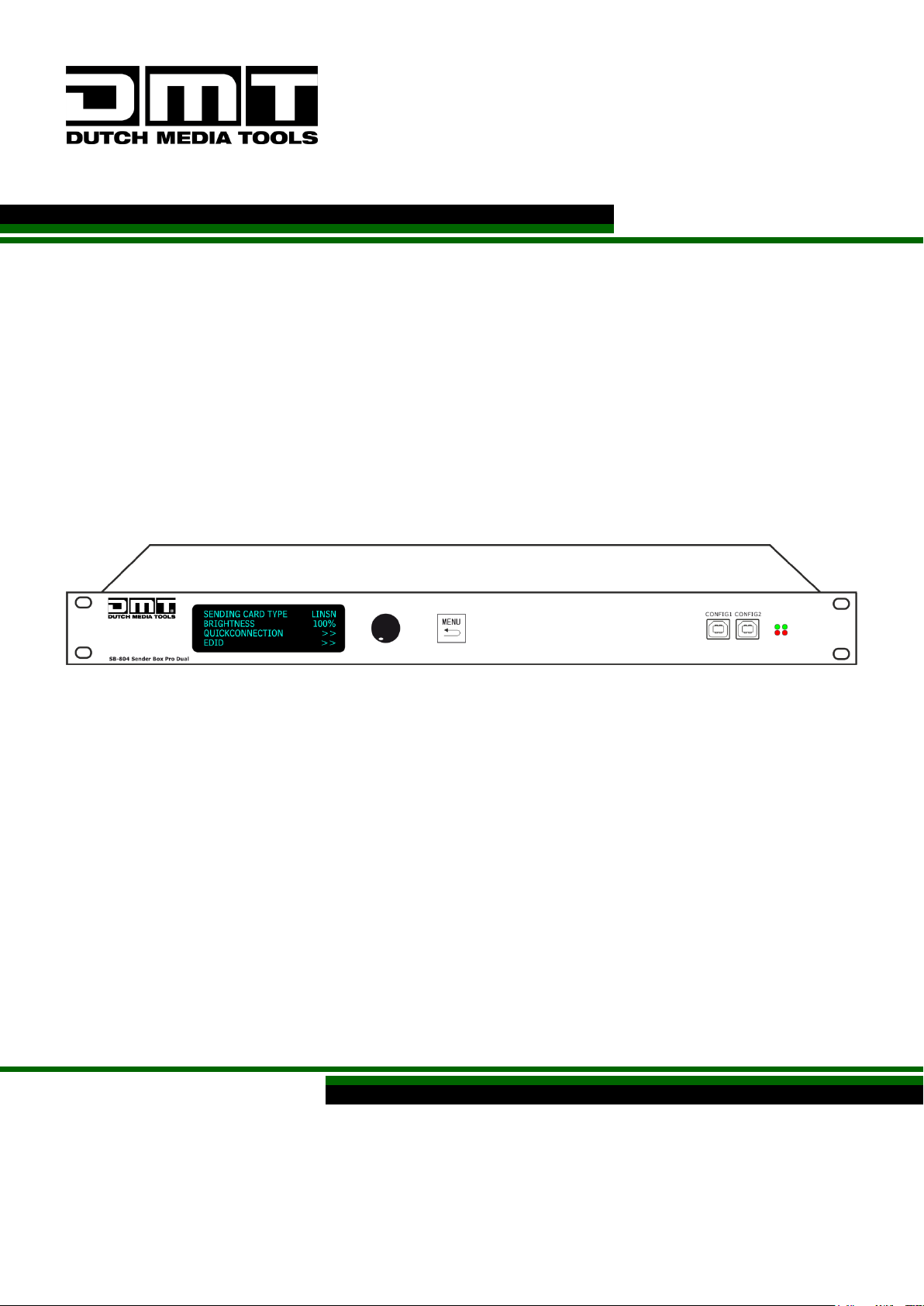
SB-804 Sender Box Pro V2
Highlite International B.V. – Vestastraat 2 – 6468 EX – Kerkrade – the Netherlands
Ordercode: 101602
MANUAL
ENGLISH
Page 2
Ordercode: 101602
SB-804 Sender Box Pro
Table of contents
Warning ............................................................................................................................................................................... 2
Unpacking Instructions ............................................................................................................................................. 2
Safety Instructions ...................................................................................................................................................... 2
Operating Determinations ....................................................................................................................................... 3
Connection with the mains ..................................................................................................................................... 4
Return Procedure ...................................................................................................................................................... 4
Claims .......................................................................................................................................................................... 4
Description of the device ................................................................................................................................................. 5
Frontside ...................................................................................................................................................................... 5
Backside ...................................................................................................................................................................... 6
Installation ........................................................................................................................................................................... 7
Set Up and Operation ....................................................................................................................................................... 7
Setup Example ........................................................................................................................................................... 7
Menu Overview.................................................................................................................................................................. 8
Main Menu Options .................................................................................................................................................. 9
1. Quick Connection ................................................................................................................................................. 9
1.1 Sending Card Type ............................................................................................................................................. 9
1.2 Sending Card No.1-2 .......................................................................................................................................... 9
1.3 Output Format...................................................................................................................................................... 9
1.4 Quick Connection .............................................................................................................................................10
1.4.1. Sending Card Set ..........................................................................................................................................10
1.4.2. Receiving Card Set .......................................................................................................................................10
1.5 Cascade .............................................................................................................................................................11
1.6 Brightness .............................................................................................................................................................11
2. SENIOR ...................................................................................................................................................................11
2.1. Receiving card Separate ...............................................................................................................................11
2.2. Color Temperature ...........................................................................................................................................11
2.3 Edid.......................................................................................................................................................................11
2.4 Gamma SET ........................................................................................................................................................11
2.5 System Info ..........................................................................................................................................................12
3. FACTORY RESET.....................................................................................................................................................12
Quick LED Screen Setup .........................................................................................................................................13
Working with the U and D ports ............................................................................................................................15
Sender Card resolutions..........................................................................................................................................18
Installation LED Studio Software ....................................................................................................................................19
LED Studio Software Serial Code: 888888 ...........................................................................................................19
LED Screen Configuration Setup ..........................................................................................................................22
Addressing LED screens ..........................................................................................................................................24
Patching the LED Screens ......................................................................................................................................25
Maintenance ....................................................................................................................................................................30
Troubleshooting ...............................................................................................................................................................30
Not working ..............................................................................................................................................................30
Product Specifications ....................................................................................................................................................31
1
Page 3
Ordercode: 101602
SB-804 Sender Box Pro
Warning
Unpacking Instructions
Immediately upon receiving this product, carefully unpack the carton and check the contents to ensure
that all parts are present, and have been received in good condition. Notify the dealer immediately and
retain packing material for inspection if any parts appear damaged from shipping or the carton itself
shows signs of mishandling. Save the carton and all packing materials. In the event that a fixture must be
returned to the factory, it is important that the fixture be returned in the original factory box and packing.
Your shipment includes:
SB-804 Sender Box Pro with PowerCON power cable 1,5 m
802 LINSN onboard sending card
User manual
Safety Instructions
Every person involved with the installation, operation and maintenance of this system has to:
• be qualified
• follow the instructions of this manual
Before you initial start-up, please make sure that there is no damage caused by transportation. Should
there be any, consult your dealer and do not use the system.
To maintain perfect condition and to ensure a safe operation, it is absolutely necessary for the user to
follow the safety instructions and warning notes written in this manual.
Please consider that damages caused by manual modifications to the system are not subject to
warranty.
This system contains no user-serviceable parts. Refer servicing to qualified technicians only.
2
Page 4

Ordercode: 101602
SB-804 Sender Box Pro
IMPORTANT:
The manufacturer will not accept liability for any resulting damages caused by the non-observance of
this manual or any unauthorized modification to the system.
Never let the power cord come into contact with other cables! Handle the power cord and all
connections with the mains with particular caution!
Never remove warning or informative labels from the unit.
Never use anything to cover the ground contact.
Never leave any cables lying around.
Do not insert objects into air vents.
Do not connect this device to a dimmerpack.
Do not switch the device on and off in short intervals, as this would reduce the device’s life.
Do not shake the device. Avoid brute force when installing or operating the device.
Only use device indoor, avoid contact with water or other liquids.
Only operate the fixture after having checked that the housing is firmly closed and all screws are
tightly fastened.
Only operate the device after having familiarized with its functions.
Avoid flames and do not put close to flammable liquids or gases.
Always keep case closed while operating.
Always allow free air space of at least 50 cm around the unit for ventilation.
Always disconnect power from the mains, when device is not used or before cleaning! Only handle
the power cord by the plug. Never pull out the plug by tugging the power cord.
Make sure that the device is not exposed to extreme heat, moisture or dust.
Make sure that the available voltage is not higher than stated on the rear panel.
Make sure that the power cord is never crimped or damaged. Check the device and the power
cord from time to time.
If device is dropped or struck, disconnect mains power supply immediately. Have a qualified
engineer inspect for safety before operating.
If the device has been exposed to drastic temperature fluctuation (e.g. after transportation), do not
switch it on immediately. The arising condensation water might damage your device. Leave the
device switched off until it has reached room temperature.
If your DMT device fails to work properly, discontinue use immediately. Pack the unit securely
(preferably in the original packing material), and return it to your DMT dealer for service.
For adult use only. Device must be installed out of the reach of children. Never leave the unit running
unattended.
Never attempt to bypass the thermostatic switch or fuses.
For replacement use fuses of same type and rating only.
The user is responsible for correct positioning and operating of the SB-804 Sender Box Pro. The
manufacturer will not accept liability for damages caused by the misuse or incorrect installation of
this device.
This device falls under protection class I. Therefore it is essential to connect the yellow/green
conductor to earth.
Repairs, servicing and electric connection must be carried out by a qualified technician.
WARRANTY: Till one year after date of purchase.
Operating Determinations
This device is not designed for permanent operation. Consistent operation breaks will ensure that the
device will serve you for a long time without defects.
The minimum distance between light-output and the illuminated surface must be bigger than 1
meter.
The maximum ambient temperature ta = 40°C must never be exceeded.
The relative humidity must not exceed 50 % with an ambient temperature of 40° C.
If this device is operated in any other way, than the one described in this manual, the product may
suffer damages and the warranty becomes void.
Any other operation may lead to dangers like short-circuit, burns, electric shock, crash etc.
You endanger your own safety and the safety of others!
Improper installation can cause serious damage to people and property!
3
Page 5
Ordercode: 101602
SB-804 Sender Box Pro
International
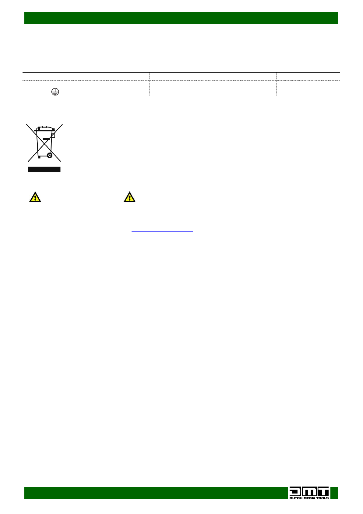
EU Cable
UK Cable
US Cable
Pin
L
BROWN
RED
YELLOW/COPPER
FASE
N
BLUE
BLACK
SILVER
NULL
YELLOW/GREEN
GREEN
GREEN
EARTH
Return Procedure
Connection with the mains
Connect the device to the mains with the power-plug.
Always pay attention, that the right color cable is connected to the right place.
Make sure that the device is always connected properly to the earth!
Returned merchandise must be sent prepaid and in the original packing, call tags will not be issued.
Package must be clearly labeled with a Return Authorization Number (RMA number). Products returned
without an RMA number will be refused. Highlite will not accept the returned goods or any responsibility.
Call Highlite 0031-455667723 or mail [email protected] and request an RMA prior to shipping the fixture.
Be prepared to provide the model number, serial number and a brief description of the cause for the
return. Be sure to properly pack fixture, any shipping damage resulting from inadequate packaging is the
customer’s responsibility. Highlite reserves the right to use its own discretion to repair or replace
product(s). As a suggestion, proper UPS packing or double-boxing is always a safe method to use.
Note: If you are given an RMA number, please include the following information on a piece of paper
inside the box:
01) Your name
02) Your address
03) Your phone number
04) A brief description of the symptoms
Claims
The client has the obligation to check the delivered goods immediately upon delivery for any shortcomings and/or visible defects, or perform this check after our announcement that the goods are at their
disposal. Damage incurred in shipping is the responsibility of the shipper; therefore the damage must be
reported to the carrier upon receipt of merchandise.
It is the customer's responsibility to notify and submit claims with the shipper in the event that a fixture is
damaged due to shipping. Transportation damage has to be reported to us within one day after receipt
of the delivery.
Any return shipment has to be made post-paid at all times. Return shipments must be accompanied with
a letter defining the reason for return shipment. Non-prepaid return shipments will be refused, unless
otherwise agreed in writing.
Complaints against us must be made known in writing or by fax within 10 working days after receipt of the
invoice. After this period complaints will not be handled anymore.
Complaints will only then be considered if the client has so far complied with all parts of the agreement,
regardless of the agreement of which the obligation is resulting.
4
Page 6
Ordercode: 101602
SB-804 Sender Box Pro
Dimensions:
482 x 358 x 44 mm (LxWxH)
19 inch x 1HE (LxH)
This Senderbox does NOT have a scaling Function
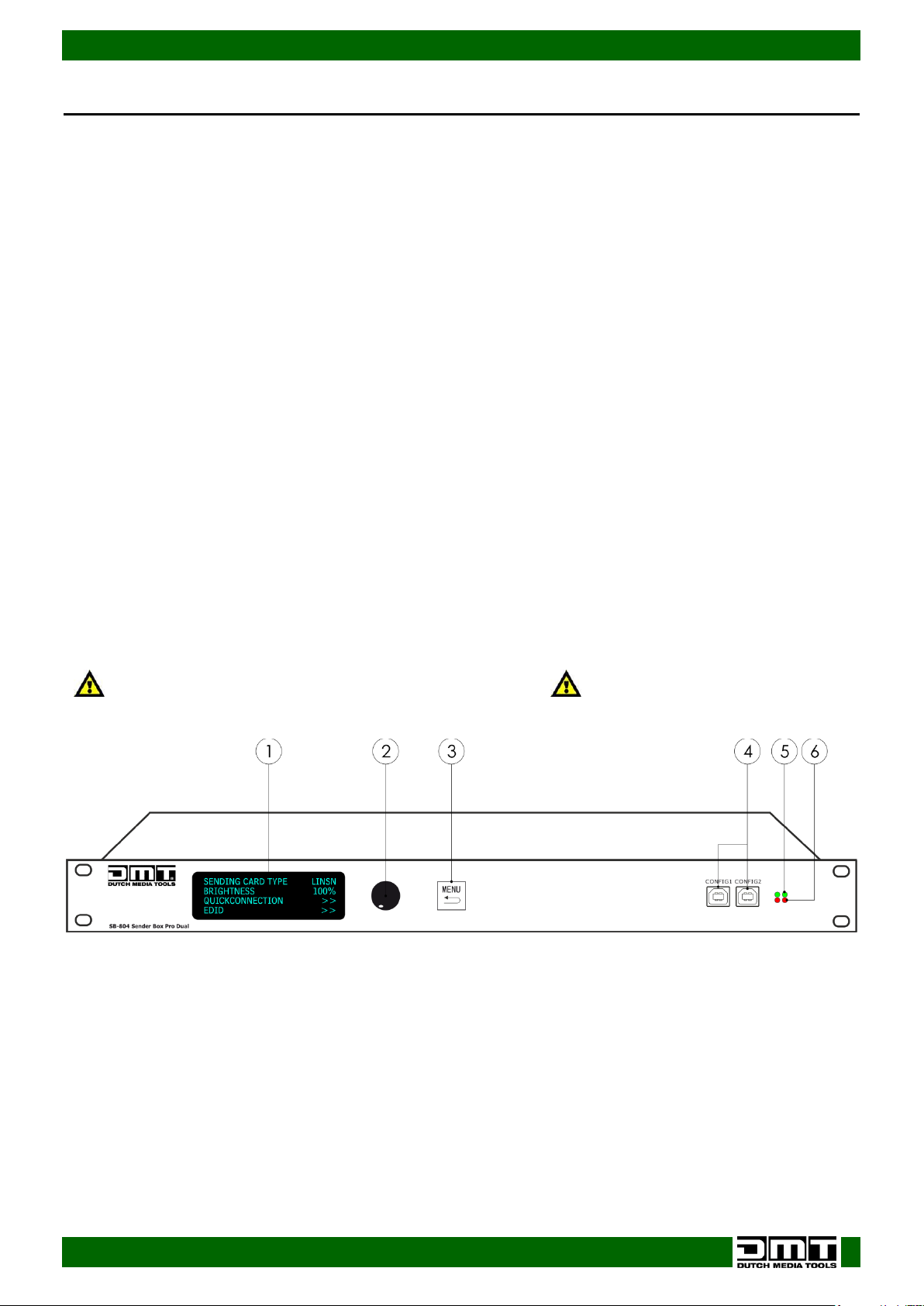
Frontside
Fig. 01
Description of the device
Features
The SB-804 is a professional sender box from DMT.
Input voltage: 85-264V AC, 50/60Hz
Power consumption: 25W
Patch LED screens without using a computer and LED Studio
2x 802 Sendercard included
Video input: 2x DVI-D + HDMI
Use a digital video (DVI or HDMI) input and convert it, so that it can be sent through a single CAT5
cable to your LED screen.
Connections are made by Neutrik Ethercon connectors, ensuring a reliable connection in any
situation.
The SB-804 is the extended version of the SB-804 with two sender cards on board it's capable of
configuring big led screen setups
Equipped with 2 sending cards which are compatible with all DMT LED screens.
With SB-804 you do not have to worry about which version LED Studio to use.
Outputs to screen: 2x 2 Ethercon(RJ45) soft-patched connectors
Power input: PowerCON IN/OUT
Setup port: USB-B, RS 232 connection on the backside.
The RS 232 is used for cascade screen brightness control: 16-levels adjustment on the front panel
Resolutions: 640 x 480, 800 x 600, 1024 x 768, 1280 x 768, 1280 x 800, 1280 x 1024, 1366 x 768, 1440 x 900,
1440 x 1080, 1600 x 576, 1600 x 900, 1600 x 1000, 1600 x 1200, 1680 x 1050, 1728 x 1296, 1920 x 1080,
1920 x 1200, 2048 x 1152, 2048 x 1280, 2560 x 1440, 2560 x 1600, custom (only available in LED Studio
software)
Cooling: Cooling fan
Standard rack size: 1U
Weight: 2,88 kg
01) LED display
02) Menu Control
Turn the menu control to select and adjust your settings. Press the button to confirm.
03) Menu/ Back Button
Press the button to go back by one step in the menu.
04) USB connector B for configuration via LED Studio Software
05) Green Signal LED
Indicates if the unit is receiving a video signal.
Flashing LED: video signal is present.
LED OFF: No video signal
06) Red LED power indicator
Indicates if the unit is switched ON.
5
Page 7
Ordercode: 101602
SB-804 Sender Box Pro
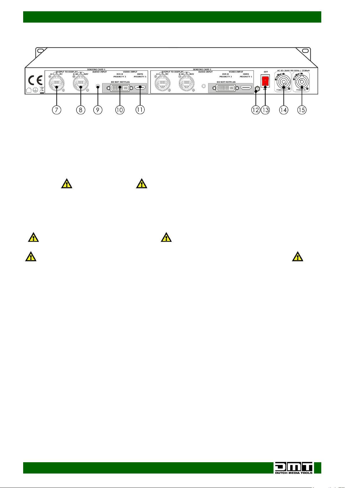
Backside
Fig. 02
Do not HOT plug HDMI or DVI
Turn OFF your device before connecting any cables!
Otherwise your device can become damaged and your warranty will become void.
07) U-port OUT to LED screen (Default port, always use U-port, but for large setups use D-port)
08) D-port OUT to LED screen
Connect the LED screen to one of these ports using a standard CAT5 or CAT6 cable with or without
the Ethercon connector.
09) Audio Input
10) DVI video IN
11) HDMI IN Does NOT have DHCP
Connect the image signal from the computer.
12) Ground/Earth connection
13) Power switch ON/OFF
14) Neutrik PowerCON OUT 85-264V AC
15) Neutrik PowerCON IN 85-264V AC
6
Page 8
Ordercode: 101602
SB-804 Sender Box Pro
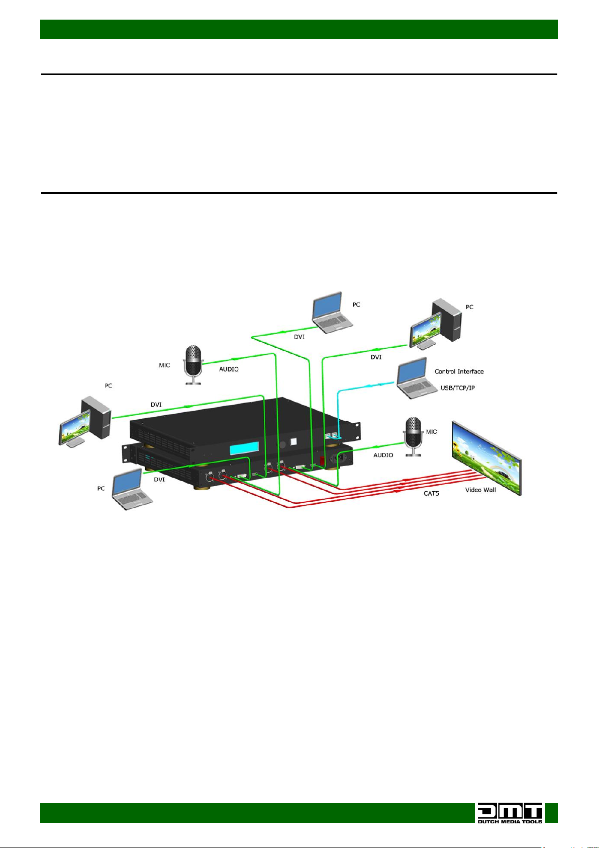
Setup Example
Fig. 03
Installation
Remove all packing materials from the SB-804. Check that all foam and plastic padding is removed.
Connect all cables.
Do not supply power before the whole system is set up and connected properly.
Always disconnect from electric mains power supply before cleaning or servicing.
Damages caused by non-observance are not subject to warranty.
Set Up and Operation
Follow the directions below, as they pertain to your preferred operation mode.
Before plugging the unit in, always make sure that the power supply matches the product specification
voltage. Do not attempt to operate a 120V specification product on 230V power, or vice versa.
7
Page 9
Ordercode: 101602
SB-804 Sender Box Pro
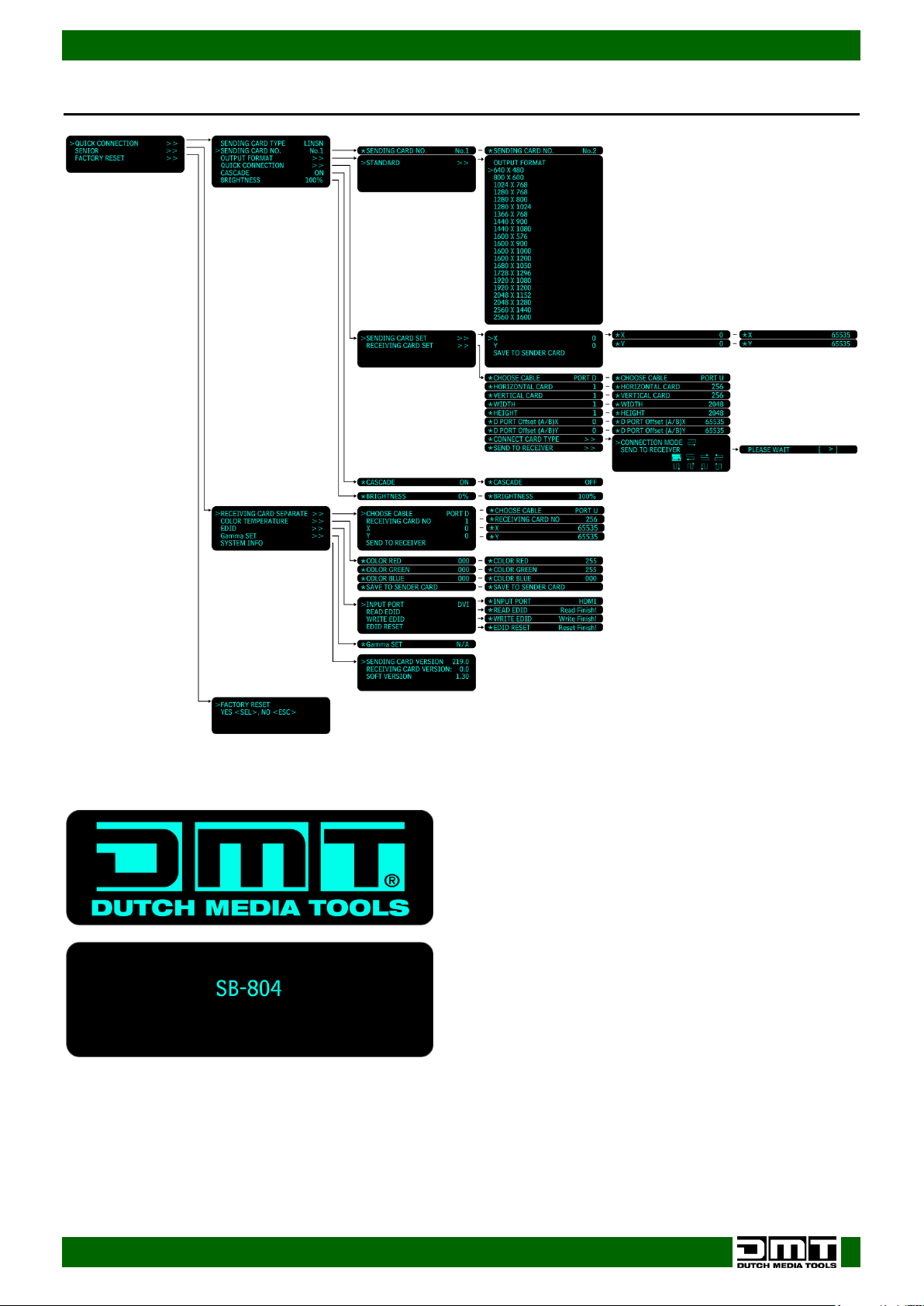
Menu Overview
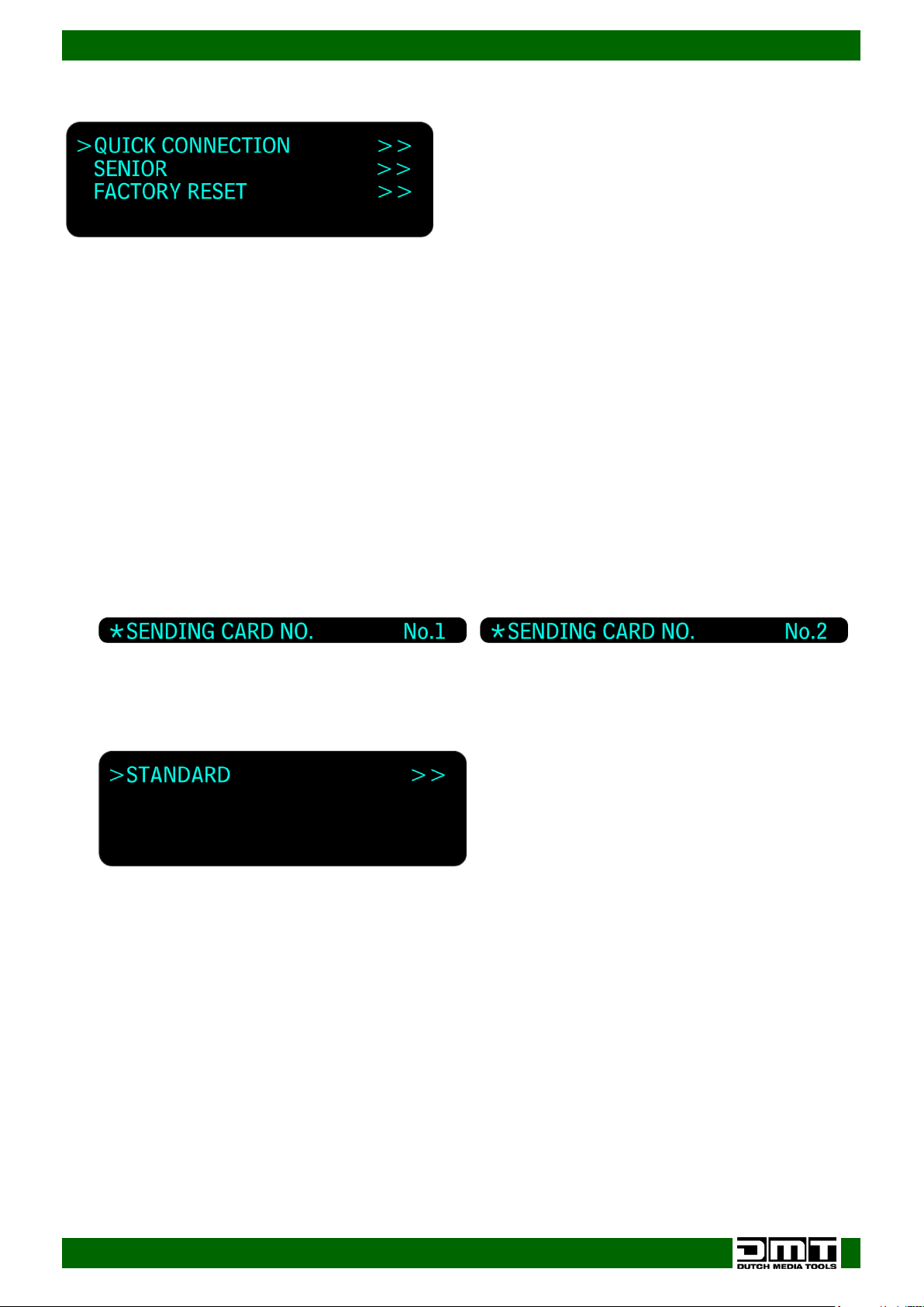
At start-up the device will show:
8
Page 10
Ordercode: 101602
SB-804 Sender Box Pro
Main Menu Options
1. Quick Connection
01) Turn the control (02) to select QUICK CONNECTION, then press control (02) to enter the menu. The
available 6 options are:
SENDING CARD TYPE
SENDING CARD No.
OUTPUT FORMAT
QUICK CONNECTION
CASCADE
BRIGHTNESS
02) Turn the control (02) to select one of the 6 options and press the control (02) to enter.
1.1 Sending Card Type
01) You cannot change or enter this menu.
1.2 Sending Card No.1-2
With this menu you can you can set which sending card you want to use.
01) Turn the control (02) to select SENDING CARD and press the control (02) to enter.
02) Turn the control (02) clockwise or counter clockwise to change the sending card from
- .
03) Press the control (02) to confirm changes.
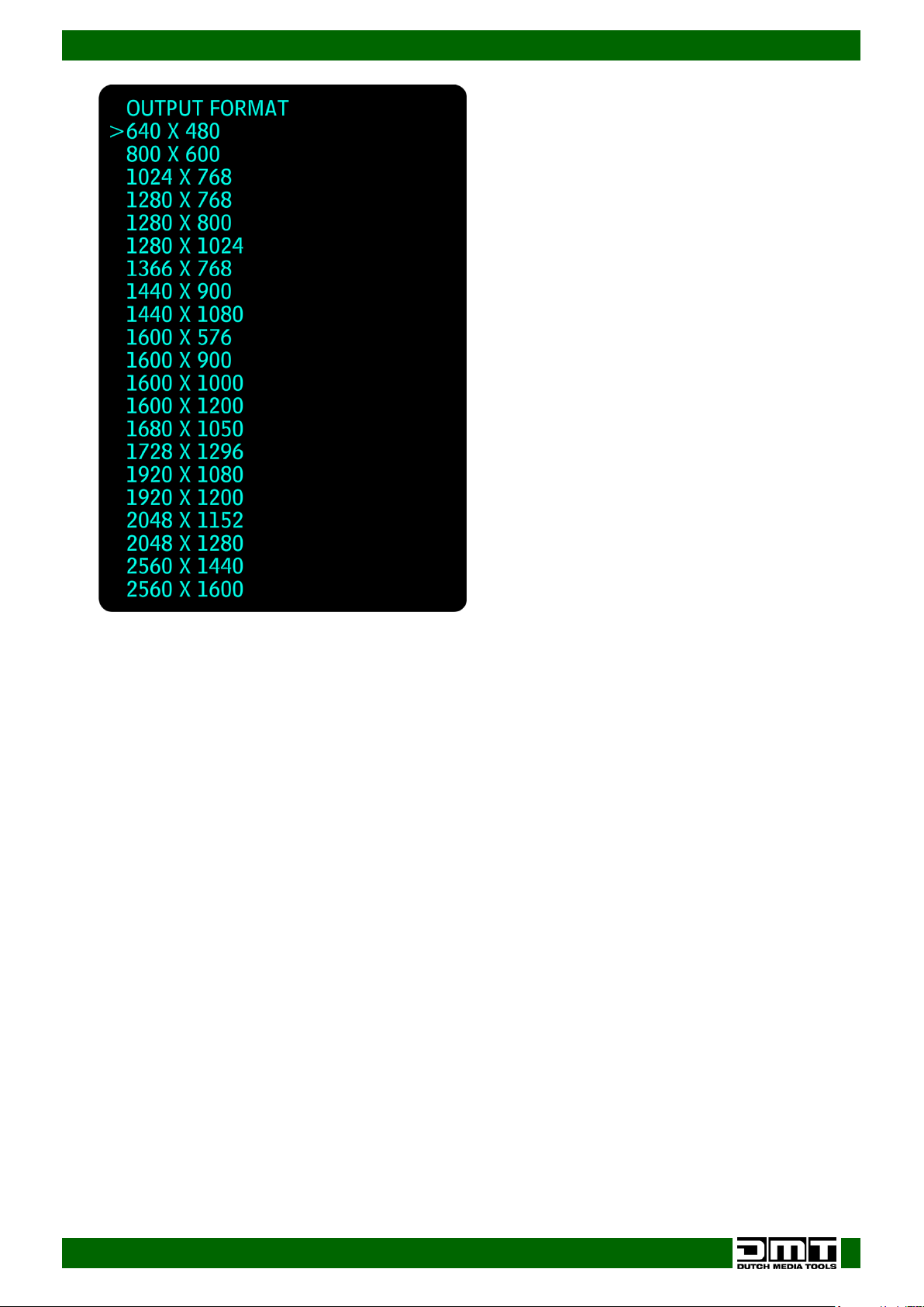
1.3 Output Format
01) Turn the control (02) to select OUTPUT FORMAT and press the control (02) to enter.
02) The display will show:
03) Press the control (02) to enter.
04) Turn the control (02) to select the desired output resolution.
9
Page 11
Ordercode: 101602
SB-804 Sender Box Pro
05) Press the control (02) to confirm your choice.
1.4 Quick Connection
03) Turn the control (02) to select QUICK CONNECTION, then press control (02) to enter the menu. The
available options are:
SENDING CARD SET
RECEIVING CARD SET
04) Turn the control (02) to select one of the 2 options and press the control (02) to enter.
1.4.1. Sending Card Set
01) Turn the control (02) to select SENDING CARD SET, then press control (02) to enter the menu.
02) In this menu, you can set the X and Y positions for the sending card.
03) Turn the control (02) to set the parameters/values.
04) Once you have adjusted the settings, turn the control (02) to select SAVE TO SENDER CARD and press
the control (02) to confirm.
1.4.2. Receiving Card Set
01) Turn the control (02) to select RECEIVING CARD SET, then press control (02) to enter the menu.
02) Turn the control (02) to set the parameters/values.
03) The available 9 options are:
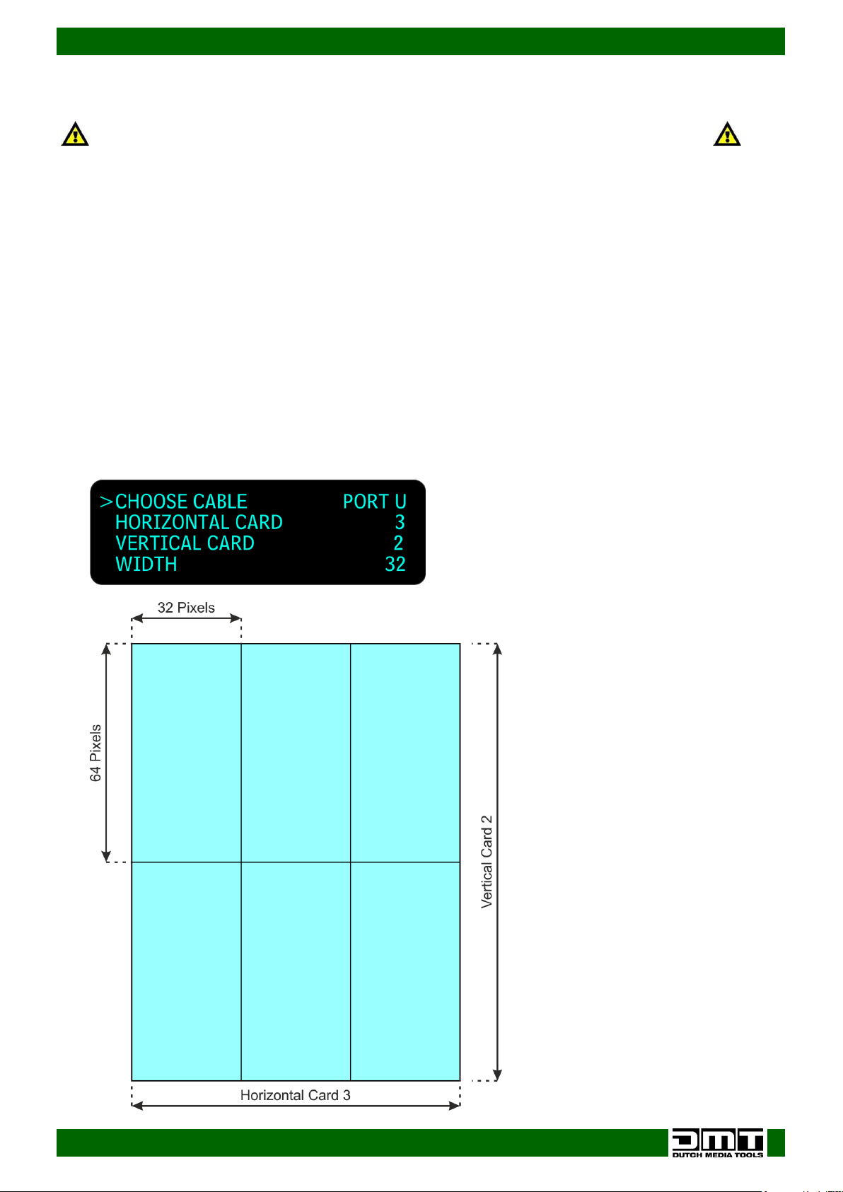
CHOOSE CABLE (PORT D or PORT U)
HORIZONTAL CARD (the number of horizontal LED screens)
VERTICAL CARD (the number of vertical LED screens)
WIDTH and HEIGHT (pixel dimensions of a LED screen). See the technical information of your LED
screen.
D PORT Offset (A/B) X and D PORT Offset (A/B) Y (set the offset positions for X and Y)
CONNECT CARD TYPE (choose one of the 8 kinds of connection)
SEND TO RECEIVER (you can send data to your receiver)
10
Page 12
Ordercode: 101602
SB-804 Sender Box Pro
1.5 Cascade
01) Press the control (02) to enter the menu and then turn the control (02) to choose ON or OFF, to
enable or disable the cascade function.
02) Press the control (02) to confirm.
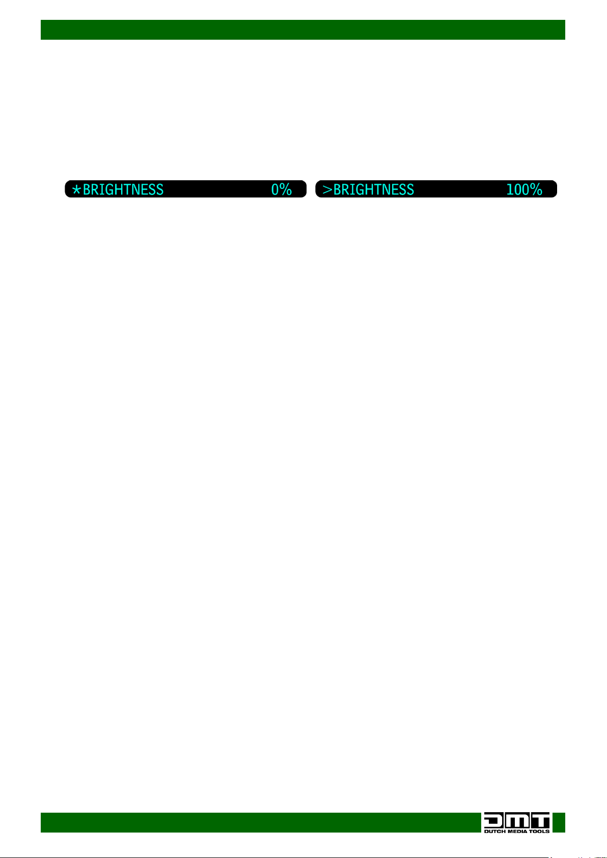
1.6 Brightness
With this menu you can you can set the brightness of your LED screen.
01) Turn the control (02) to select BRIGHTNESS and press the control (02) to enter.
02) Turn the control (02) clockwise or counter clockwise to change the brightness from
- .
03) Press the control (02) to confirm changes.
2. SENIOR
05) Turn the control (02) to select SENIOR, then press control (02) to enter the menu. The available 5
options are:
RECEIVING CARD SEPARATE
COLOR TEMPERATURE
EDID
Gamma SET
SYSTEM INFO
06) Turn the control (02) to select one of the 5 options and press the control (02) to enter.
2.1. Receiving card Separate
01) Turn the control (02) to select SENIOR, then press control (02) to enter the menu.
02) Turn the control (02) to set the parameters/values.
03) The available 5 options are:
Choose Cable (Port A/Port B)
Receiving card No. (1-256)
X and Y positions for the receiving card
SEND TO RECEIVER (once you have set the X and Y positions, you can send them to the receiver)
2.2. Color Temperature
01) Turn the control (02) to select SENIOR, then press control (02) to enter the menu.
02) Turn the control (02) to set the parameters/values.
03) Set the color intensity for Red, Green and Blue and save them to the sender card:
Red 0-255
Green 0-255
Blue 0-255
2.3 Edid
01) Turn the control (02) to select EDID, then press control (02) to enter the menu.
02) Turn the control (02) to set the parameters/values.
03) The available 4 options are:
INPUT PORT (choose the input source: DVI or HDMI)
READ EDID (read EDID from input)
WRITE EDID (write EDID to input)
EDID RESET (choose the output port and reset EDID)
04) Press the control (02) to confirm
2.4 Gamma SET
01) Turn the control (02) to select Gamma SET and press the control (02) to enter.
02) You cannot change any Gamma settings with this version.
11
Page 13

Ordercode: 101602
SB-804 Sender Box Pro
2.5 System Info
01) Turn the control (02) to select SYSTEM INFO and press the control (02) to enter.
02) You cannot change any settings, you can only view:
SENDING CARD VERSION (view the sending card version)
RECEIVING CARD VERSION (view the receiving card version)
SOFT VERSION (view the currently installed software version)
3. FACTORY RESET
01) Press the control (02) to enter the menu.
02) Turn the control (02) clockwise or counter clockwise to Rest (SEL) or don’t reset (NO). Once have
chosen the desired option, press the control (02) to reset or the MENU button (03) to return to the
previous screen.
12
Page 14
Ordercode: 101602
SB-804 Sender Box Pro
Turn OFF your device before connecting any cables!
Otherwise your device can become damaged and your warranty will become void.
Quick LED Screen Setup
01) Connect HDMI or DVI source.
(When both are connected, the HDMI source will have priority. If there is an HDMI error, or if it is not
connected, the Sender Box Pro will switch automatically to DVI).
02) Connect the LED screen to output port U.
03) Switch the Sender Box Pro ON.
04) Press the MENU button (03) to enter the main menu.
05) Turn the control (02) to select QUICK CONNECTION in the main menu and press the control (02) to
enter.
06) Turn the control (02) to select QUICK CONNECTION again and press the control (02) to enter.
07) Turn the control (02) to select RECEIVING CARD SET and press the control (02) to enter.
08)
09) Turn the control (02) to select CHOOSE CABLE, press the control (02) and turn the control (02) to
select port U. Press the control (02) to confirm.
10) Turn the control (02) to select HORIZONTAL/VERTICAL CARD (how many horizontal and vertical LED
screens are used in the setup).
11) Press the control (02) and turn it to adjust the values.
12) Press the control (02) to confirm.
13
Page 15
Ordercode: 101602
SB-804 Sender Box Pro
Always seen from the front of your LED screen
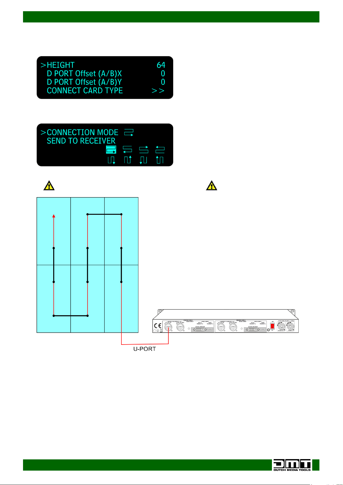
13) Turn the control (02) to select Width and Height (the pixel dimensions of one LED screen). In our
example, we have used an E12,5 LED screen with 32 pixels (width) x 64 pixels (height). Please leave
the D PORT Offset settings set to 0:
14) Turn the control (02) to select CONNECT CARD TYPE.
15) Press the control (02) to enter.
Connection Mode is the routing of your data line.
16) Turn the control (02) to select CONNECTION MODE and press the control (02) to enter.
17) Turn the control (02) to choose one of the 8 ways in which the LED screens are connected with the
main data cable.
18) Press the control (02) to confirm your choice.
19) Turn the control (02) to select SEND TO RECEIVER and press the control (02) to confirm.
14
Page 16
Ordercode: 101602
SB-804 Sender Box Pro
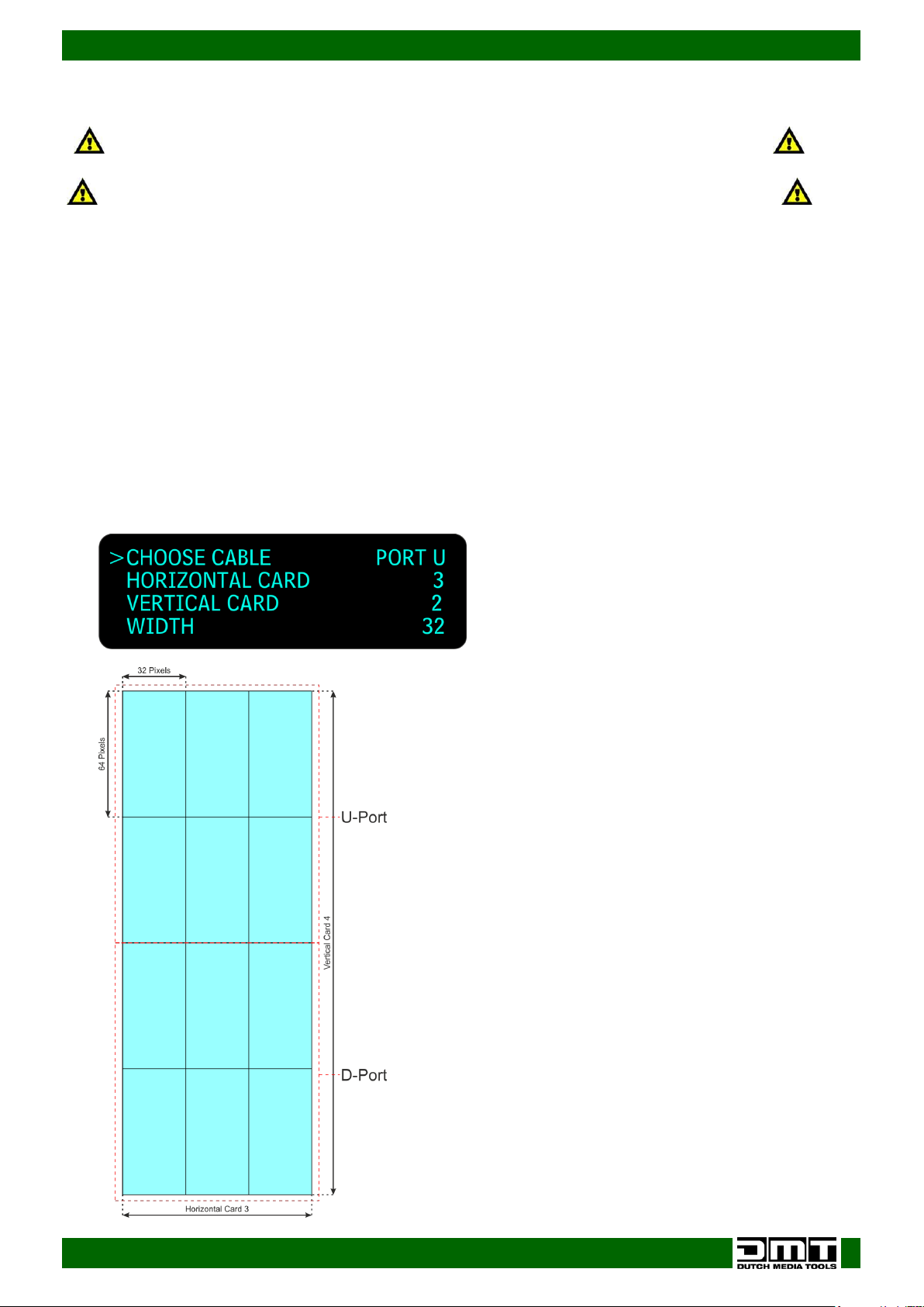
Use this mode when the maximum pixel height is reached on U port
Turn OFF your device before connecting any cables!
Otherwise your device can become damaged and your warranty will become void.
Working with the U and D ports
01) Connect HDMI or DVI source.
(When both are connected, HDMI will have priority, when HDMI fails or if it is not connected, the
Sender Box Pro will auto switch to DVI).
02) Connect the ports U and D.
03) Switch the Sender Box Pro ON.
04) Turn the control (02) to select QUICK CONNECTION in the main menu and press the control (02) to
enter.
05) Turn the control (02) to select QUICK CONNECTION again and press the control (02) to enter.
06) Turn the control (02) to select RECEIVING CARD SET and press the control (02) to enter.
07) Turn the control (02) to select CHOOSE CABLE, press the control (02) and turn the control (02) to
select port U. Press the control (02) to confirm.
08) Turn the control (02) to select HORIZONTAL/VERTICAL CARD (how many horizontal and vertical LED
screens are used in the setup).
09) Press the control (02) and turn it to adjust the values.
10) Press the control (02) to confirm.
15
Page 17
Ordercode: 101602
SB-804 Sender Box Pro
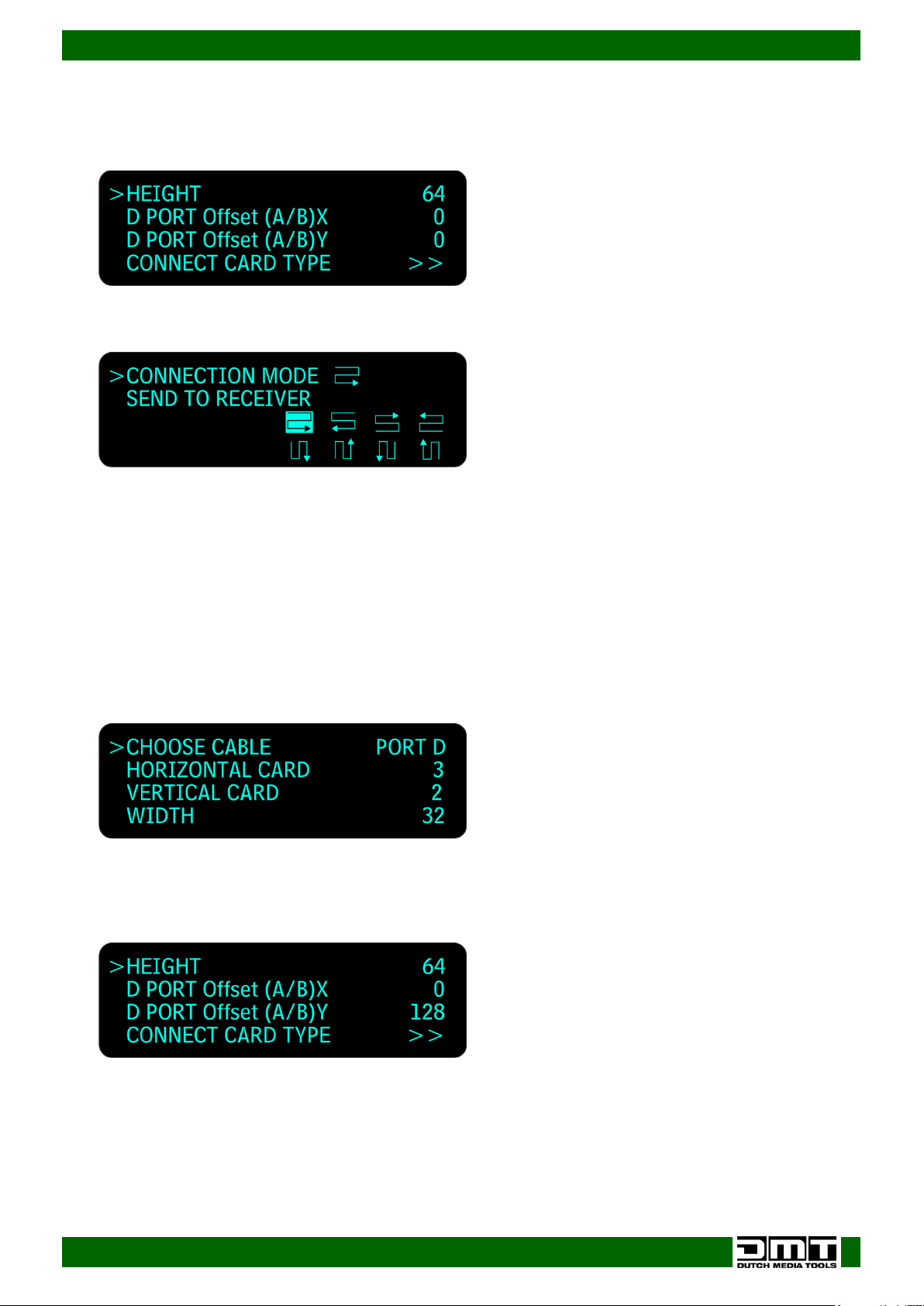
11) Turn the control (02) to select Width and Height. Press the control (02) and then turn it to adjust the
values. These are the pixel dimensions of one LED screen. In our example we have used an E12,5 LED
screen with 32 pixels (width) x 64 pixels (height). Please leave the D PORT Offset settings set to 0:
12) Press the control (02) to confirm.
13) Turn the control (02) to select CONNECT CARD TYPE.
14) Press the control (02) to enter.
15) Turn the control (02) to select CONNECTION MODE and press the control (02) to enter.
16) Turn the control (02) to choose one of the 8 ways in which the LED screens are connected with the
main data cable.
17) Press the control (02) to confirm your choice.
18) Turn the control (02) to select SEND TO RECEIVER and press the control (02) to confirm.
19) Turn the control (02) to the left, to return to the previous menu screen.
20) Turn the control (02) to select CHOOSE CABLE, press the control (02) and then turn it to set the output
D port.
21) Turn the control (02) to select HORIZONTAL/VERTICAL CARD (how many horizontal and vertical LED
screens are used in the setup on the D port).
22) Press the control (02) and turn it to adjust the values.
23) Press the control (02) to confirm.
24) Turn the control (02) to select Width and Height. Press the control (02) and then turn it to adjust the
values. These are the pixel dimensions of one LED screen. In our example we have used an E12,5 LED
screen with 32 pixels (width) x 64 pixels (height). Set the offset of the D port with the options D PORT
Offset (A/B)X and D PORT Offset (A/B)Y.
16
Page 18
Ordercode: 101602
SB-804 Sender Box Pro
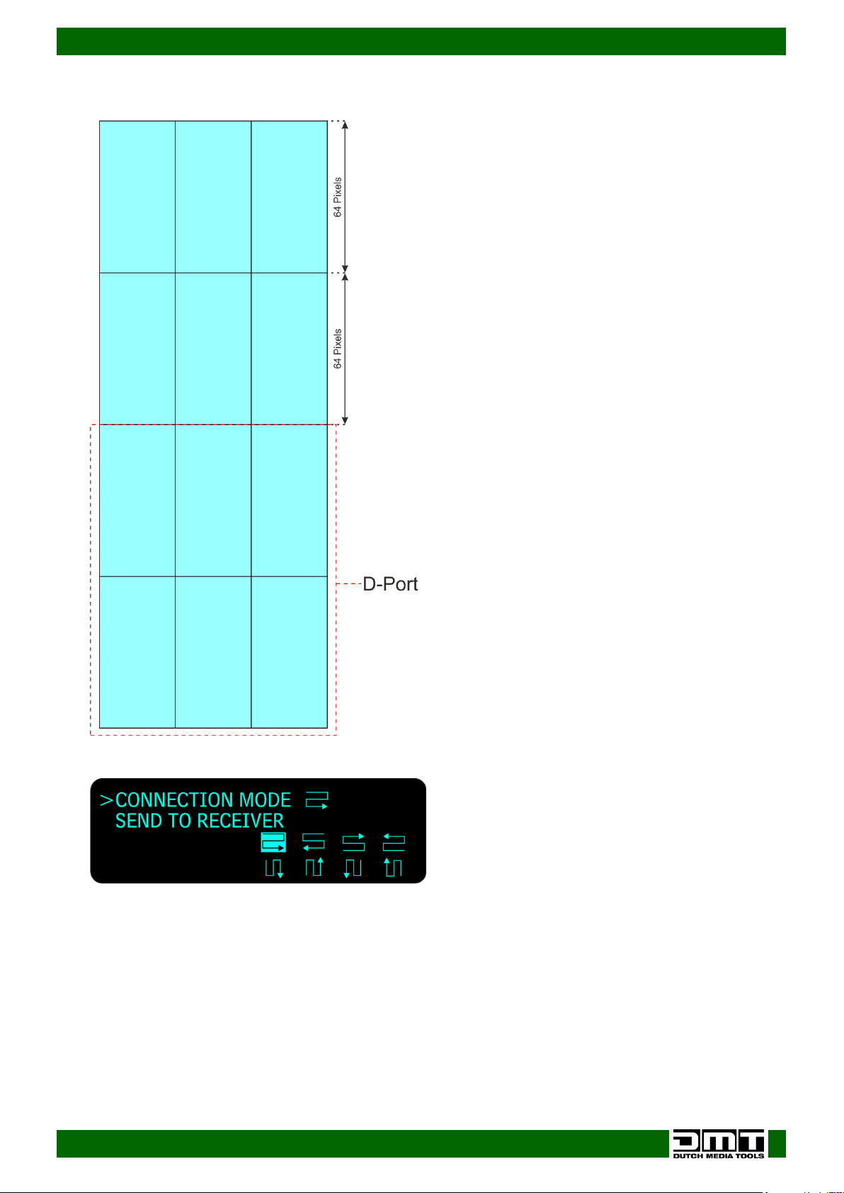
25) To calculate the offset, add the 2 LED screens from the U port: 64 pixels + 64 pixels = 128 pixels.
Therefore, the D port will start at Pixel 129 (vertically).
26) Turn the control (02) to select CONNECT CARD TYPE and press the control (02) to enter.
27) Turn the control (02) to select CONNECTION MODE, press the control (02) and then turn it choose one
of the 8 ways in which the LED screens are connected with the main data cable.
28) Press the control (02) to confirm your choice.
29) Turn the control (02) to select SEND TO RECEIVER and press the control (02) to confirm.
17
Page 19
Ordercode: 101602
SB-804 Sender Box Pro
Turn OFF your device before connecting any cables!
Otherwise your device can become damaged and your warranty will become void.
Sender Card resolutions
Sender Card supports following resolutions
60HZ output: TS802(D) support capability
No Max support Note
Width Height Total
1 2048 320 655360 1 cable
3 1984 320 634880 1 cable
4 1920 320 614400 1 cable
5 1856 352 653312 1 cable
6 1792 352 630784 1 cable
7 1728 352 608256 1 cable
8 1664 384 638976 1 cable
9 1600 384 614400 1 cable
10 1536 416 638976 1 cable
11 1472 416 612352 1 cable
12 1408 448 630784 1 cable
13 1344 480 645120 1 cable
14 1280 512 655360 1 cable
15 1216 512 622592 1 cable
16 1152 512 589824 1 cable
17 1088 512 557056 1 cable
18 1024 640 655360 1 cable
19 896 640 573440 1 cable
20 832 640 532480 1 cable
21 768 640 491520 1 cable
22 704 640 450560 1 cable
23 640 640 409600 1 cable
60HZ output: TS802(D) support capability
No Max support Note
Width Height Total
1 2048 640 1310720 2 cables
3 1920 672 1290240 2 cables
4 1856 704 1306624 2 cables
5 1792 720 1290240 2 cables
6 1728 736 1271808 2 cables
7 1664 768 1277952 2 cables
8 1600 800 1280000 2 cables
9 1536 832 1277952 2 cables
10 1472 880 1295360 2 cables
11 1408 928 1306624 2 cables
12 1344 960 1290240 2 cables
13 1280 1024 1310720 2 cables
14 1216 1024 1245184 2 cables
15 1152 1024 1179648 2 cables
16 1088 1024 1114112 2 cables
18
Page 20
Ordercode: 101602
SB-804 Sender Box Pro
ONLY download LED Studio from our website. Click the following link: LED studio Software
Do NOT download the LED Studo software from other sites
Installation LED Studio Software
LED Studio Software Serial Code: 888888
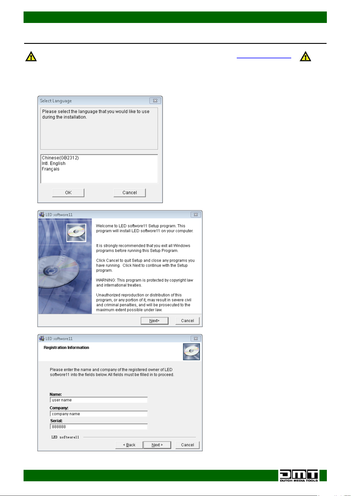
01) Double click to open the installation file of LED Studio software.
02) A small window will open and you will have to select the preferred language.
03) Click on Next.
04) Fill in the requested information: Username, Company Name and Serial Code: 888888.
19
Page 21
Ordercode: 101602
SB-804 Sender Box Pro
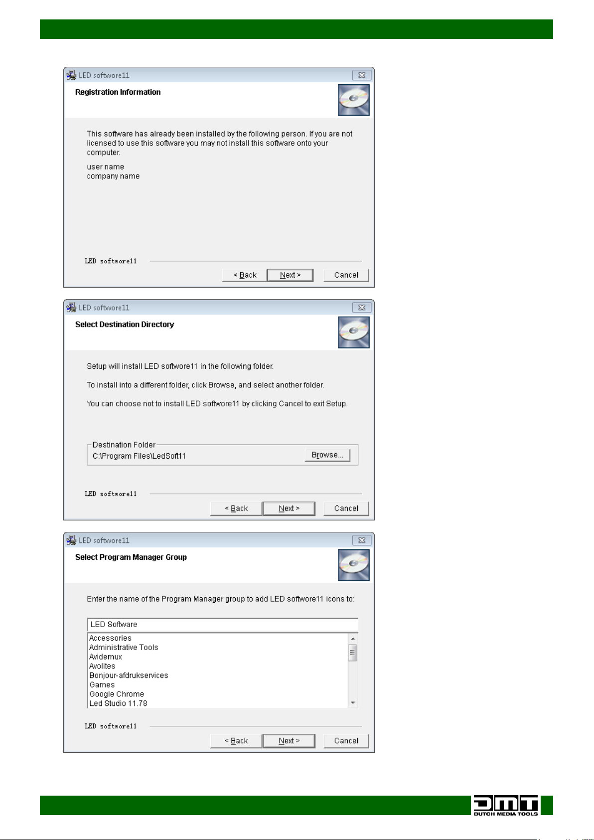
05) Click on Next.
06) Select the destination folder and click on Next.
07) Click on Next.
20
Page 22
Ordercode: 101602
SB-804 Sender Box Pro
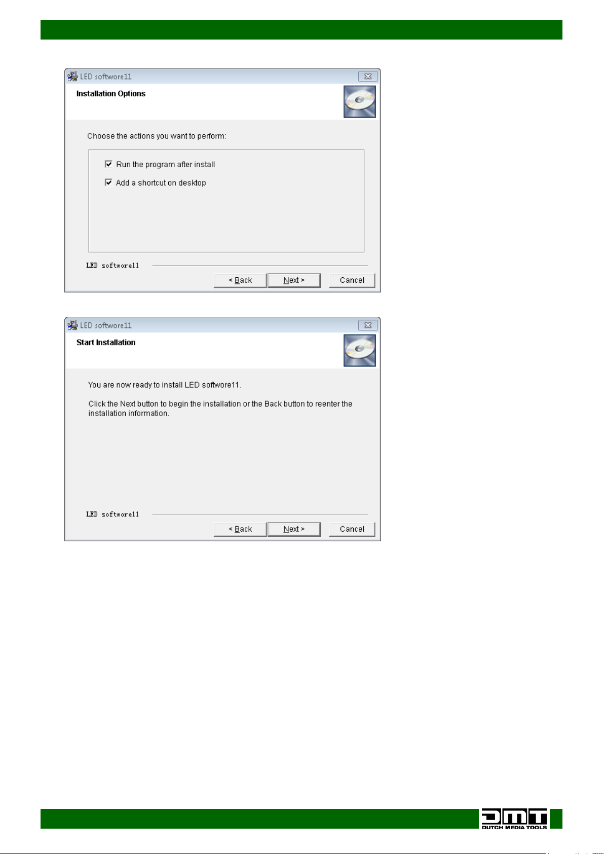
08) Click on Next.
09) Click on Next.
10) Installation is now complete.
21
Page 23
Ordercode: 101602
SB-804 Sender Box Pro
The LED Studio software is Windows native.
If you use Mac OS: use Bootcamp and the Windows License.
LED Screen Configuration Setup
The receiver card is the PCB which is built into the LED screen.
It communicates with the sender card, inside the SB-804, via the CAT-5 data cable.
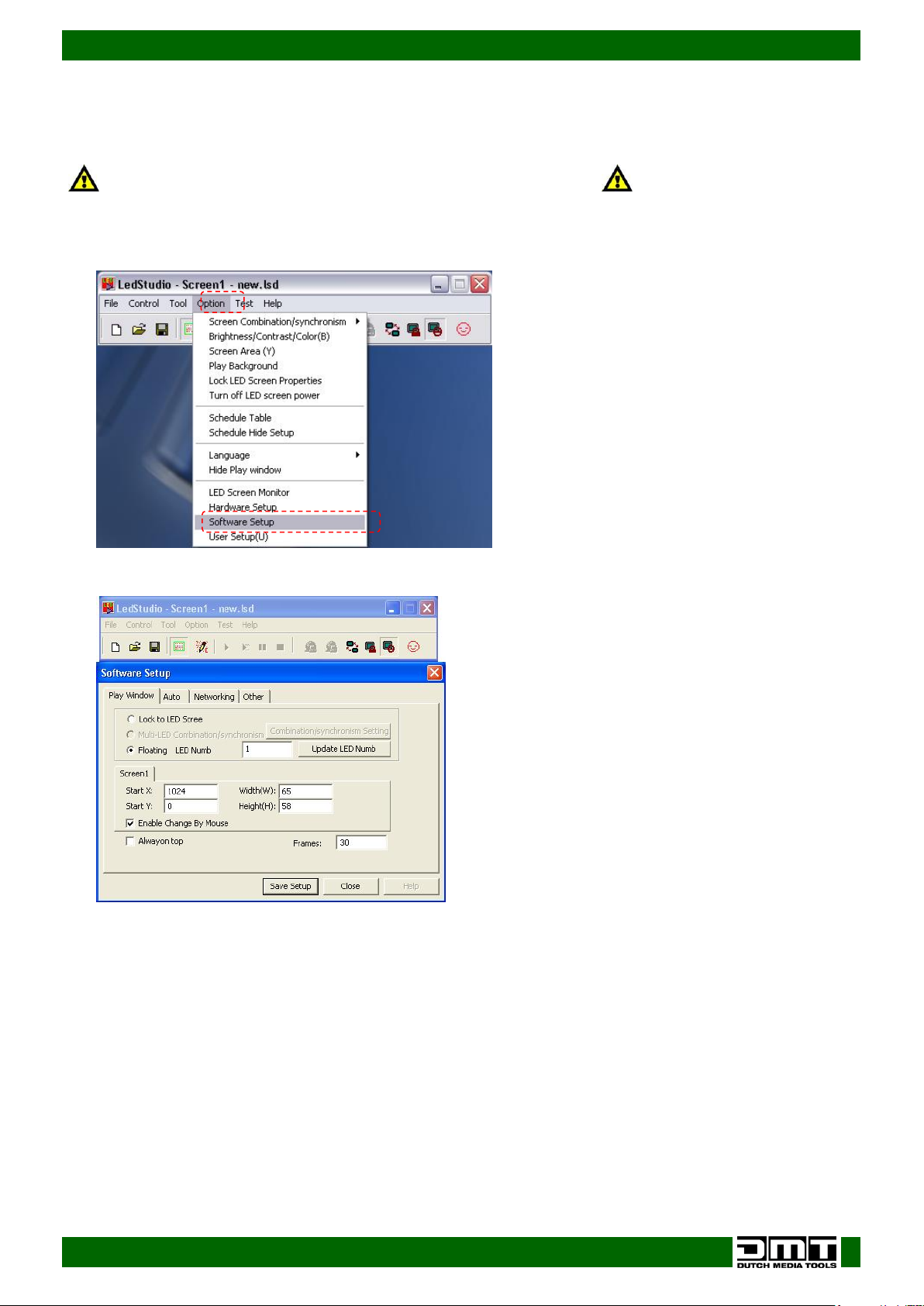
01) After opening the main window of the LED Studio, please go to Option menu and click on Software
Setup.
02) Enter the Software Setup screen.
22
Page 24
Ordercode: 101602
SB-804 Sender Box Pro
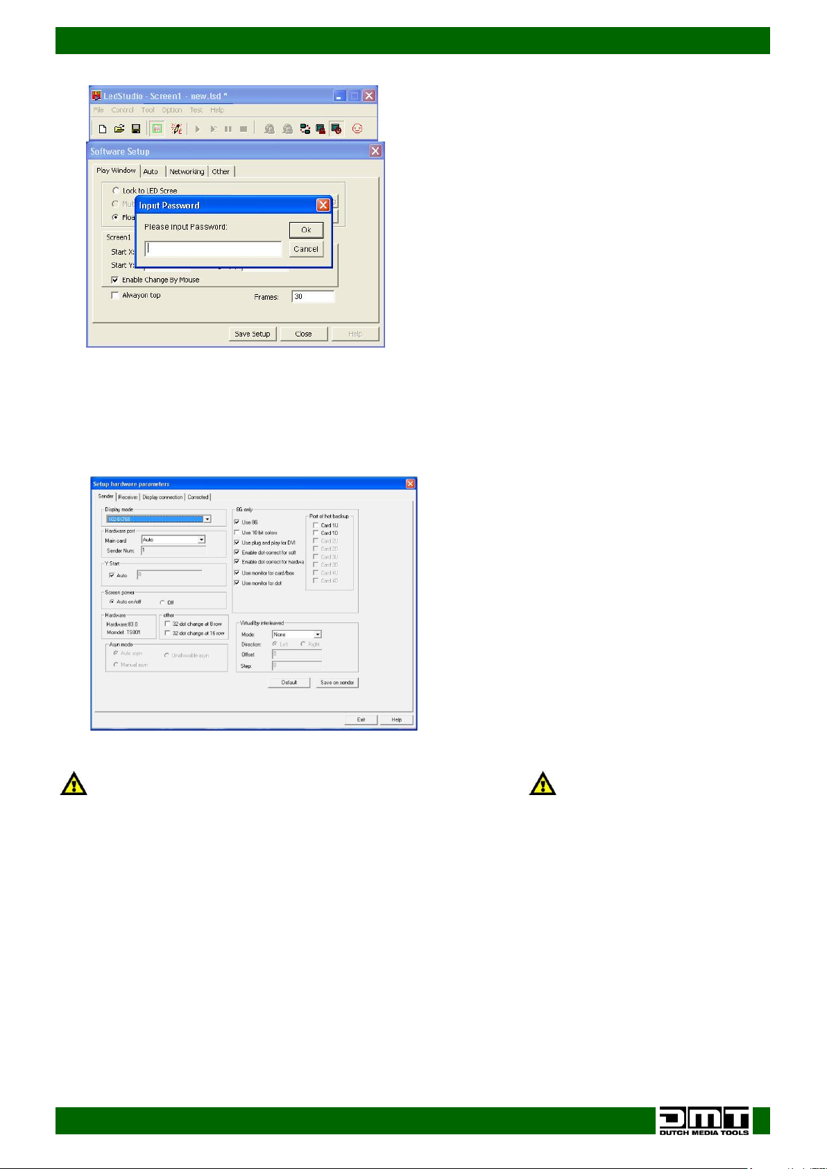
First click Default to reset the sender card in the senderbox.
You will return to the factory default setting.
03) When the Software Setup screen appears, just type in linsn.
Note: no dialog box will appear on the screen to type it in.
04) After this, a pop-up window appears on the screen, requesting a password.
05) Insert the password. The password is“168”.
06) Click on Ok.
07) Once you have inserted the correct password, the following hardware setup appears on the screen:
Sender Setup
Then click Save on sender to save your settings.
If the pixel size of your LED screen (see Display mode) is not larger than 1024x768, your settings are OK.
Make sure that the display resolution on the DVI/HDMI Input is 1024x768.
Otherwise, choose the proper resolution from the drop-down menu.
23
Page 25
Ordercode: 101602
SB-804 Sender Box Pro
The LED Studio software is Windows native.
If you use Mac OS: use Bootcamp and the Windows License.
Addressing LED screens
LED screens are addressed via the LED Studio software.
01) Connect your LED screen to the U port.
02) Connect your computer to the Sender Box via USB.
03) Power on the Sender Box and start the LED Studio software.
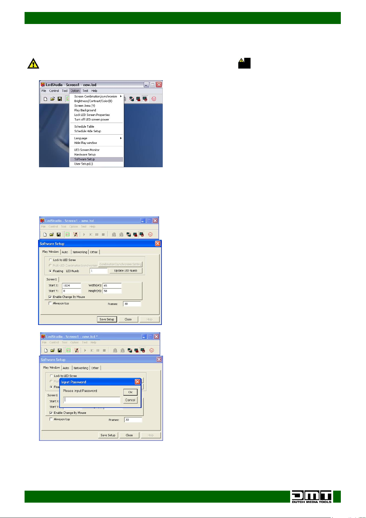
04) Go to Option menu and click on Software Setup.
05) Enter the screen of software setup.
04) When the Software Setup window appears on the screen, just type in linsn.
Note: no dialog box will appear on the screen to type it in.
05) After this, a pop-up window appears on the screen, requesting a password.
06) Insert the password. The password is“168”.
07) Click on Ok.
24
Page 26
Ordercode: 101602
SB-804 Sender Box Pro
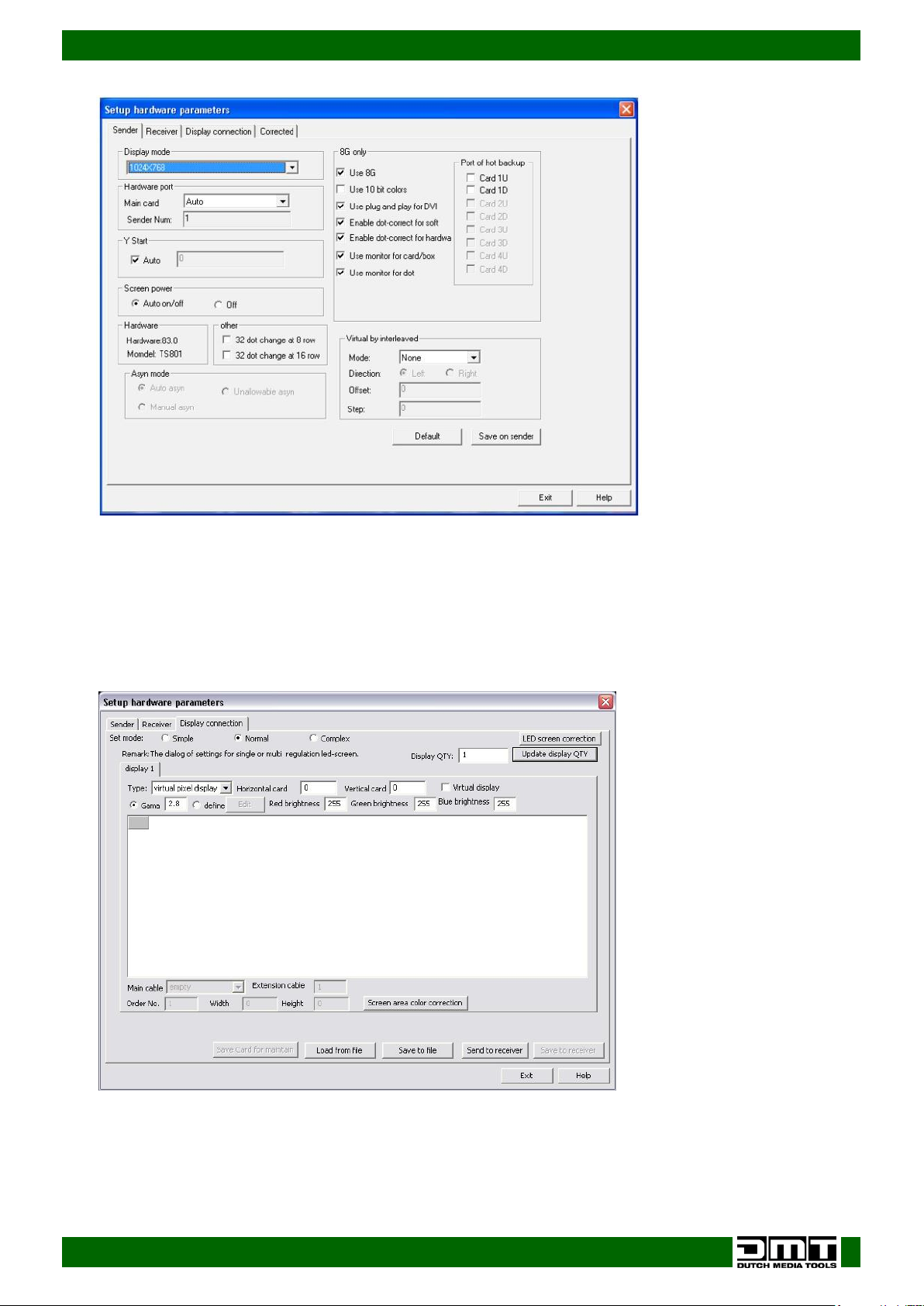
08) In the new window, go to the Display connection tab, and click on it.
Patching the LED Screens
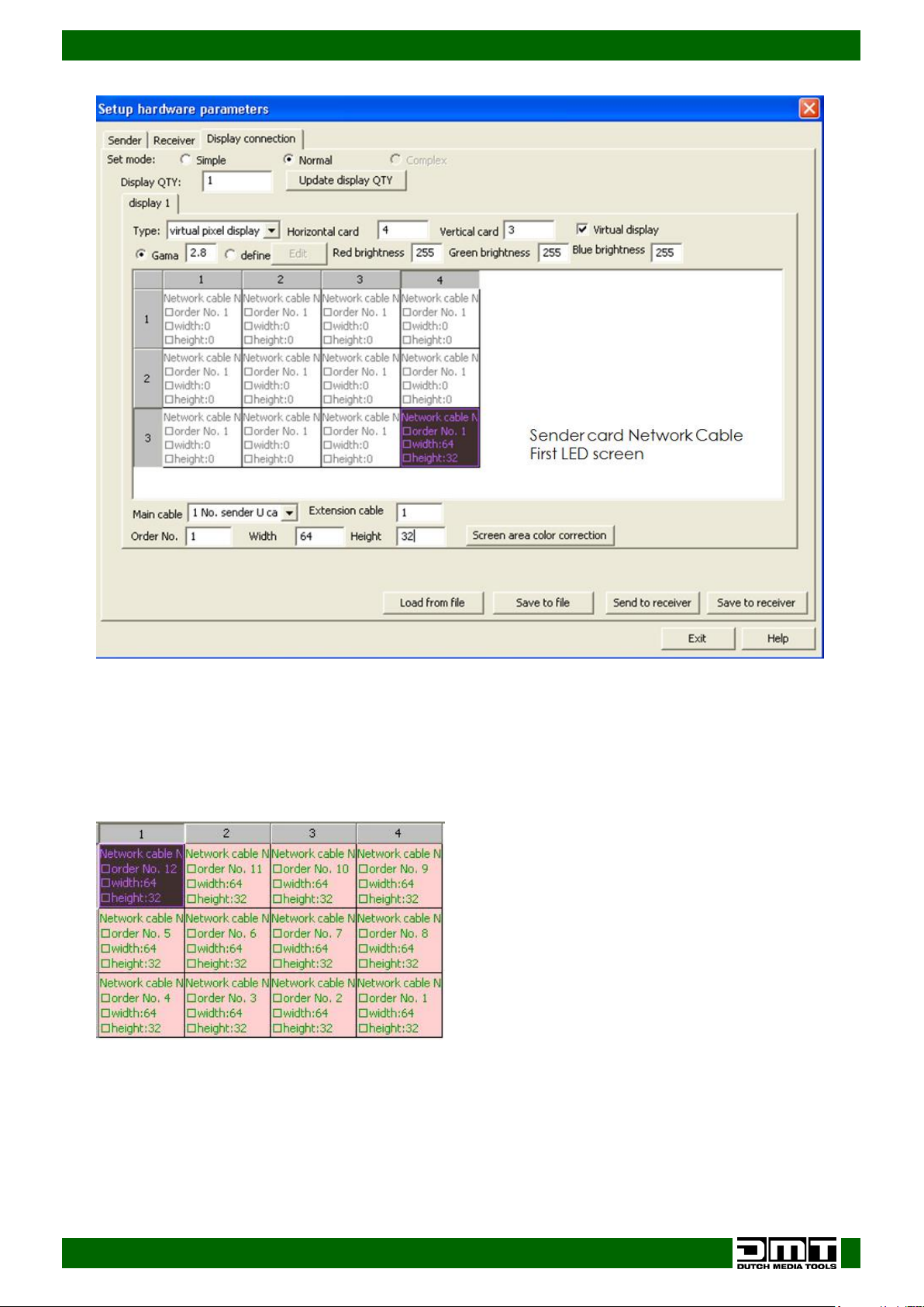
We have to set the amount of LED screens which we want to control.
01) We can do this by entering the number of LED screens in our Display connection panel.
02) First, enter how many screens are to be used horizontally (Horizontal card) and vertically (Vertical
card)
As an example we have chosen 4 x 3 LED screens (4=Width, 3=Height).
03) After setting up the number of LED screens, the display will show:
25
Page 27
Ordercode: 101602
SB-804 Sender Box Pro
04) The First LED screen is the LED screen to which the data/network cable from sender card is
connected.
05) Set Order No. to 1.
06) Please, make sure to select the proper main cable (1 No. sender U cable).
07) Set width and height per LED screen (this information can be found in the specifications from your
LED screen). When it is set, click on the first block. The information will turn green.
08) Now use the arrow keys on your keyboard to jump to the next LED screen in your setup.
26
Page 28
Ordercode: 101602
SB-804 Sender Box Pro
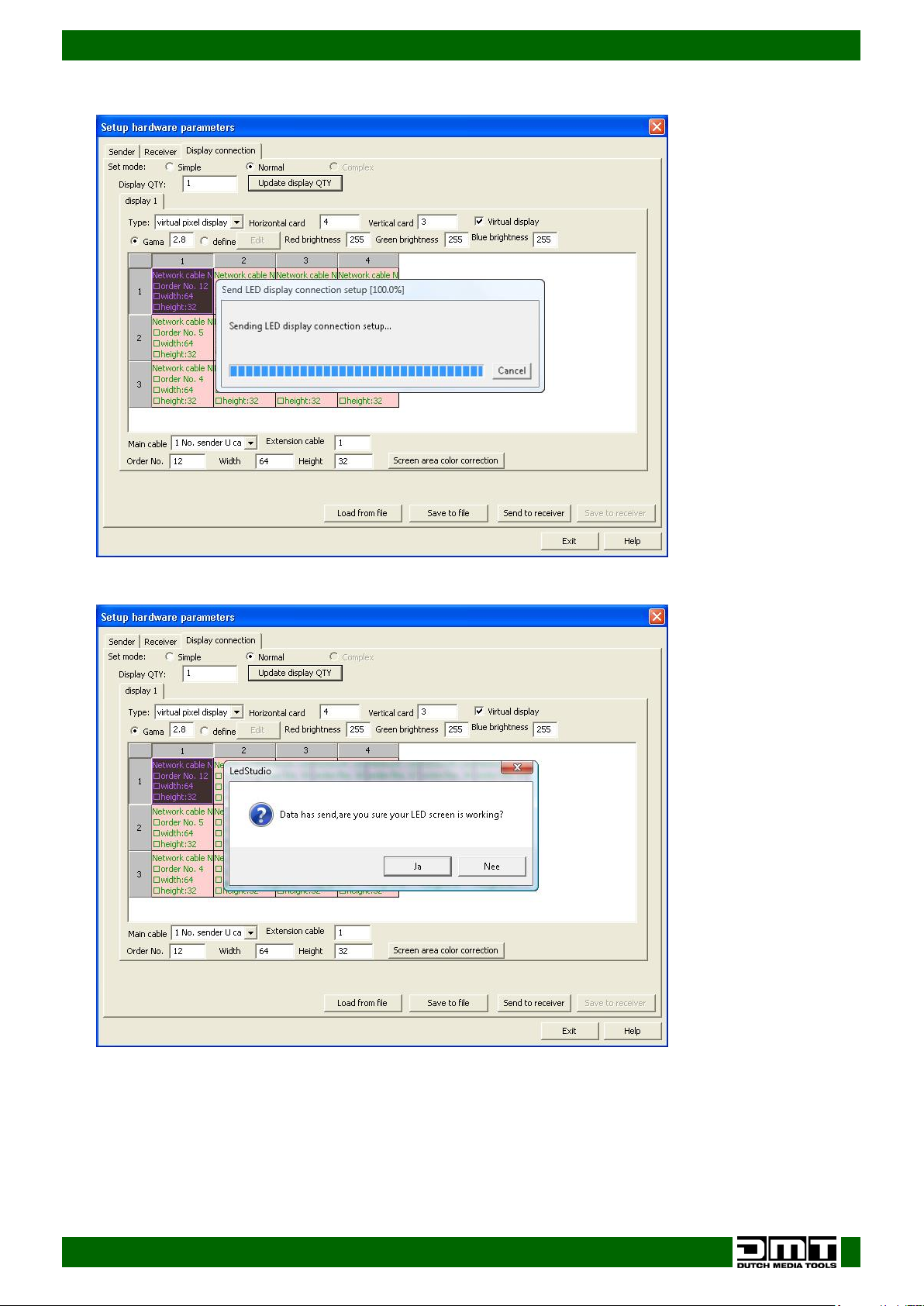
09) Click on Send to receiver. The display will show:
10) The data will be uploaded to the receiver.
11) Click on Ok, when the procedure is finished.
27
Page 29
Ordercode: 101602
SB-804 Sender Box Pro
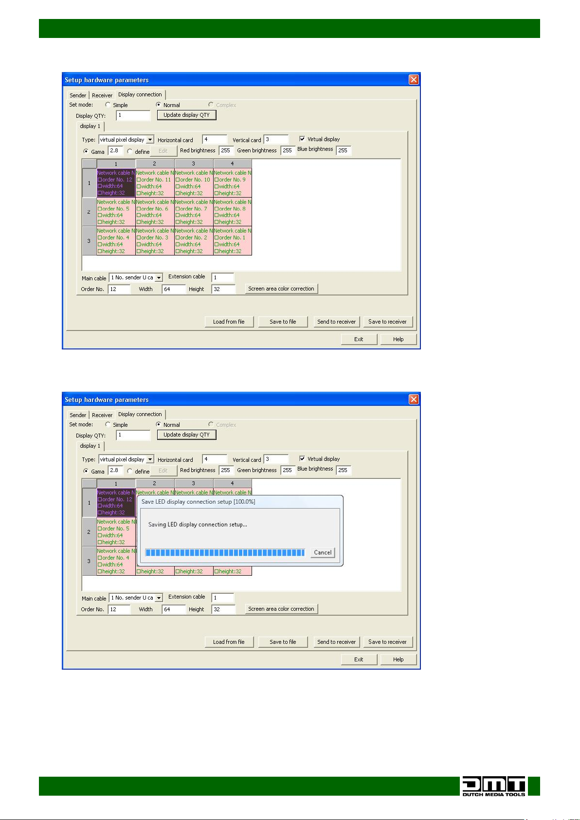
12) The display will show:
13) Now Save to receiver button will become active.
14) Click on Save to receiver.
15) The data will now be saved to the receiver.
28
Page 30
Ordercode: 101602
SB-804 Sender Box Pro
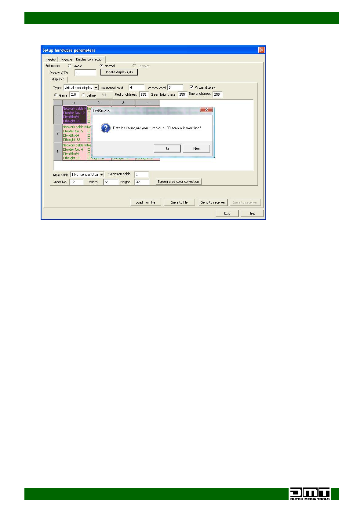
16) After that, the display will show:
17) Click on Ok. The procedure is finished.
29
Page 31
Ordercode: 101602
SB-804 Sender Box Pro
Maintenance
The DMT SB-804 requires almost no maintenance. However, you should keep the unit clean. Disconnect
the mains power supply and then wipe the cover with a damp cloth. Wipe the front panel clean with
glass cleaner and a soft cloth. Do not use alcohol or solvents. Do not immerse in liquid.
Keep connections clean. Disconnect electric power, and then wipe the Video and audio connections
with a damp cloth. Make sure connections are thoroughly dry before linking equipment or supplying
electric power.
The operator has to make sure that safety-related and machine-technical installations are to be
inspected by an expert after every year in the course of an acceptance test.
The operator has to make sure that safety-related and machine-technical installations are to be
inspected by a skilled person once a year.
The following points have to be considered during the inspection:
01) All screws used for installing the device or parts of the device have to be tightly connected and must
not be corroded.
02) There may not be any deformations on housings, fixations and installation spots.
03) Mechanically moving parts like axles, eyes and others may not show any traces of wearing.
04) The electric power supply cables must not show any damages or material fatigue.
Troubleshooting
This troubleshooting guide is meant to help solve simple problems.
If a problem occurs, carry out the steps below in sequence until a solution is found. Once the unit
operates properly, do not carry out following steps.
Not working
If the Sender Box does not operate properly, refer servicing to a technician.
Suspect two potential problem areas as: the power supply, the cables.
01) Power supply. Check that the unit is plugged into an appropriate power supply.
02) All cables. Please check all connections and all cables. Return the Sender Box to your DMT dealer.
03) If all of the above appears to be O.K., plug the unit in again.
04) If you are unable to determine the cause of the problem, do not open the Sender Box, as this may
damage the unit and the warranty will become void.
05) Return the device to your DMT dealer.
30
Page 32
Ordercode: 101602
SB-804 Sender Box Pro
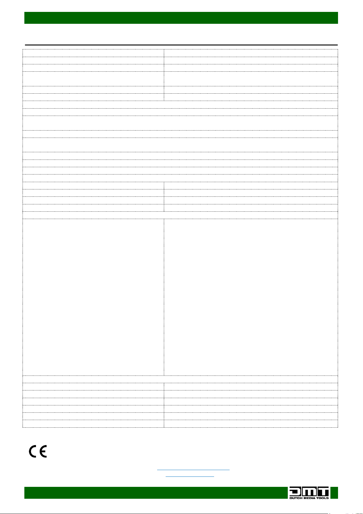
Model:
DMT SB-804 sender box
Input Voltage:
85-264V AC, 50/60Hz
Power consumption:
25W (full output)
Dimensions:
482 x 358 x 44mm (LxWxH)
19 inch x 1HE (LxH)
Weight:
2,88 kg
Operating and Programming:
Patch LED screens without using a computer and LED Studio
Use a digital video (DVI or HDMI) input and convert it, so that it can be sent through a single CAT5 cable to
your LED screen.
Connections are made by Neutrik Ethercon connectors, ensuring a reliable connection in any situation.
The SB-804 is the extended version of the SB-804 with two sender cards on board it's capable of configuring
big led screen setups
Equipped with 2 sending cards which are compatible with all DMT LED screens.
With SB-804 you do not have to worry about which version LED Studio to use.
Setup port: USB-B, RS 232 connection on the backside.
The RS 232 is used for cascade screen brightness control: 16-levels adjustment on the front panel
Cooling:
Cooling fan
Video input:
2x DVI-D + HDMI
Power input:
PowerCON IN/OUT
Outputs to screen:
2x 2 Ethercon(RJ45) soft-patched connectors
2x 802 Sendercard included
Resolutions:
640 x 480
800 x 600
1024 x 768
1280 x 768
1280 x 800
1280 x 1024
1366 x 768
1440 x 900
1440 x 1080
1600 x 576
1600 x 900
1600 x 1000
1600 x 1200
1680 x 1050
1728 x 1296
1920 x 1080
1920 x 1200
2048 x 1152
2048 x 1280
2560 x 1440
2560 x 1600
custom (only available in LED Studio software)
Max. ambient temperature ta:
40°C
Max. housing temperature tB:
80°C
Minimum distance:
Minimum distance from flammable surfaces:
0,5 m
Minimum distance to lighted object:
1 m
Design and product specifications are subject to change without prior notice.
Website: www.DutchMediaTools.info
Email: [email protected]
Product Specifications
31
Page 33

Ordercode: 101602
SB-804 Sender Box Pro
32
Page 34

Ordercode: 101602
SB-804 Sender Box Pro
33
Page 35

Ordercode: 101602
SB-804 Sender Box Pro
34
Page 36

©2016 D.M.T.
 Loading...