

Page 1
PRESENTER CONTROL
ORDERCODE 100801
Page 2

Congratulations!
You have bought a great, innovative product from DMT.
The DMT Presenter Control brings excitement to any venue. Whether you want simple plug-&-play action
or a sophisticated DMX show, this product provides the effect you need.
You can rely on DMT, for more excellent lighting products. We design and manufacture professional light
equipment for the entertainment industry. New products are being launched regularly. We work hard to
keep you, our customer, satisfied.
For more information: [email protected]
You can get some of the best quality, best priced products on the market from DMT. So next time, turn to
DMT for more great lighting equipment.
Always get the best -- with DMT !
Thank you!
Page 3

1
2
3
4
5
5
6
7
9
9
9
9
9
10
10
10
11
11
11
12
12
13
13
14
14
15
15
17
19
19
20
20
20
21
22
23
24
DMT
DMT Presenter Control™ Product Guide
Warning..…...................................................................................…………………………………………....................
Safety-instructions…………………………………………………………………………………………......................
Operating Determinations…………………………………………………………………………………...................
Description..…..............................................................................……….…………………………………..................
Features…….……………………………………………………………………………………….……...…...................
Overview………………………………………………………………………………………………………...................
Backside………………………………………………………………………………………………………....................
Installation...............................................................................…...…………………………………….…......................
Set up examples....................................................................................................................................................
Programming the device......................................................................................................................................
Controlling a projector with the PC using the remote terminal.......................................................................
Controlling a projector with the PC using IR.......................................................................................................
Controlling an electric projection screen with the PC......................................................................................
Controlling light with the PC.................................................................................................................................
Switch detection with the PC...............................................................................................................................
Controlling audio equipment...............................................................................................................................
Controlling video equipment...............................................................................................................................
Controlling VGA equipment.................................................................................................................................
MIC input and audio input...................................................................................................................................
Infrared transmission.............................................................................................................................................
Software installation.................................................................................................................................................
Running the set up program................................................................................................................................
Curriculum schedule............................................................................................................................................
Projector setup......................................................................................................................................................
Serial port control..................................................................................................................................................
Requirements for the RS232 code.......................................................................................................................
IR remote control...................................................................................................................................................
DVD IR remote control..........................................................................................................................................
Saving the setup....................................................................................................................................................
Sending the program to the host........................................................................................................................
Maintenance...................................................................................………..………….…….……………....................
Troubleshooting............................................................................………………….………………….….....................
Product Specifications.................................................................……………….…….………………….....................
Appendix 1: Pin definition of programming cable and Infrared learning cable...............................................
Appendix 2: Block diagram....................................................................................................................................
Appendix 3: ASCII table...........................................................................................................................................
Page 4

2
WARNING
Unpacking Instructions
Immediately upon receiving this product, carefully unpack the carton and check the contents to ensure
that all parts are present, and have been received in good condition. Notify the dealer immediately and
retain packing material for inspection if any parts appear damaged from shipping or the carton itself
shows signs of mishandling. Save the carton and all packing materials. In the event that a fixture must be
returned to the factory, it is important that the fixture be returned in the original factory box and packing.
Your shipment includes:
• DMT Presenter Control
• User manual
• 2 stereo audio cables 3,5mm jack – 1,4m – 3,5mm jack.
• 3 stereo audio cables 3,5mm jack - 1,4m – RCA.
• 2 Programming/ communication cable.
• 1 IEC power cable.
• 1 IR-emitting LED.
• 1 CD-Rom containing remote software.
• 1 Wireless remote control.
Return Procedure
Returned merchandise must be sent prepaid and in the original packing, call tags will not be issued.
Package must be clearly labeled with a Return Authorization Number (RMA number). Products returned
without an RMA number will be refused. Highlite will not accept the returned goods or any responsibility.
Call Highlite 0031-455667723 or mail [email protected] and request an RMA prior to shipping the fixture.
Be prepared to provide the model number, serial number and a brief description of the cause for the
return. Be sure to properly pack fixture, any shipping damage resulting from inadequate packaging is the
customer’s responsibility. Highlite reserves the right to use its own discretion to repair or replace
product(s). As a suggestion, proper UPS packing or double-boxing is always a safe method to use.
Note: If you are given an RMA number, please include the following information on a piece of paper
inside the box:
1) Your name
2) Your address
3) Your phone number
4) A brief description of the symptoms
Claims
The client has the obligation to check the delivered goods immediately upon delivery for any shortcomings and/or visible defects, or perform this check after our announcement that the goods are at their
disposal. Damage incurred in shipping is the responsibility of the shipper; therefore the damage must be
reported to the carrier upon receipt of merchandise.
It is the customer's responsibility to notify and submit claims with the shipper in the event that a fixture is
damaged due to shipping. Transportation damage has to be reported to us within one day after receipt
of the delivery.
Any return shipment has to be made post-paid at all times. Return shipments must be accompanied with
a letter defining the reason for return shipment. Non-prepaid return shipments will be refused, unless
otherwise agreed in writing.
Complaints against us must be made known in writing or by fax within 10 working days after receipt of the
invoice. After this period complaints will not be handled anymore.
Complaints will only then be considered if the client has so far complied with all parts of the agreement,
regardless of the agreement of which the obligation is resulting.
FOR YOUR OWN SAFETY, PLEASE READ THIS USER MANUAL CAREFULLY
BEFORE YOUR INITIAL START-UP!
Page 5
3
WARNING
FOR YOUR OWN SAFETY, PLEASE READ THIS USER MANUAL CAREFULLY
BEFORE YOUR INITIAL START-UP!
SAFETY INSTRUCTIONS
Every person involved with the installation, operation and maintenance of this device has to:
- be qualified
- follow the instructions of this manual
Before your initial start-up, please make sure that there is no damage caused by transportation. Should
there be any, consult your dealer and do not use the device.
To maintain perfect condition and to ensure a safe operation, it is absolutely necessary for the user to
follow the safety instructions and warning notes written in this manual.
Please consider that damages caused by manual modifications to the device are not subject to
warranty.
This device contains no user-serviceable parts. Refer servicing to qualified technicians only.
IMPORTANT:
The manufacturer will not accept liability for any resulting damages caused by the nonobservance of this manual or any unauthorized modification to the device.
Never let the power-cord come into contact with other cables! Handle the power-cord and all
connections with the mains with particular caution!
Never remove warning or informative labels from the unit.
Never leave any cables lying around.
Do not open the device and do not modify the device.
Do not connect this device to a dimmerpack.
Do not switch the device on and off in short intervals, as this would reduce the system’s life.
Only use device indoor, avoid contact with water or other liquids.
Avoid flames and do not put close to flammable liquids or gases.
Always disconnect power from the mains, when device is not used or before cleaning! Only
handle the power-cord by the plug. Never pull out the plug by tugging the power-cord.
Make sure that the device is not exposed to extreme heat, moisture or dust.
Make sure that the available voltage is not higher than stated on the rear panel.
Make sure that the power-cord is never crimped or damaged. Check the device and the power-
cord from time to time.
If device is dropped or struck, disconnect mains power supply immediately. Have a qualified
engineer inspect for safety before operating.
If the device has been exposed to drastic temperature fluctuation (e.g. after transportation), do
not switch it on immediately. The arising condensation water might damage your device. Leave
the device switched off until it has reached room temperature.
If your DMT device fails to work properly, discontinue use immediately. Pack the unit securely
(preferably in the original packing material), and return it to your DMT dealer for service.
For replacement use fuses of same type and rating only.
CAUTION!
Keep this device away from rain and moisture!
Unplug mains lead before opening the housing!
CAUTION! Be careful with your operations.
With a dangerous voltage you can suffer
a dangerous electric shock when touching the wires!
Page 6

4
Repairs, servicing and electric connection must be carried out by a qualified technician.
WARRANTY: Till one year after date of purchase.
OPERATING DETERMINATIONS
If this device is operated in any other way, than the one described in this manual, the product may suffer
damages and the warranty becomes void.
Any other operation may lead to dangers like short-circuit, burns, electric shock, lamp explosion, crash
etc.
You endanger your own safety and the safety of others!
Improper installation can cause serious damage to people and property !
Page 7
5
Description of the device
Features
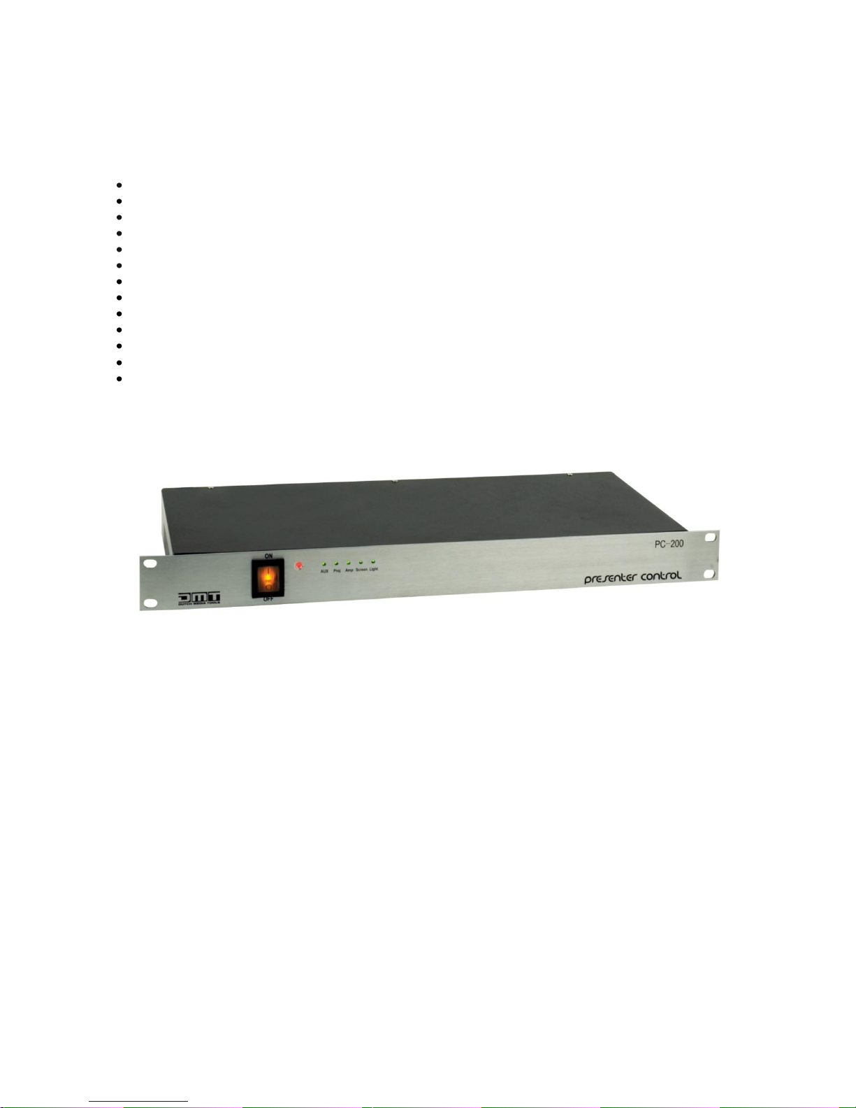
The Presenter Control is used for switching one of six program sources to a beamer or large screen and
at the same time enabling remote control and/ or automated control of several functions. The presenter
control is easy to operate. It is therefore ideally suited to be used in conference rooms, multimedia rooms,
college or classrooms.
AC 90-230V - 50-60Hz
Combined 6 x 1 VGA/ video - audio matrix switching module.
6.3mm jack MIC input.
2 x Video out (RCA).
2 x RGB out.
Audio out (stereo 3,5mm mini jack).
2 x RS232 interface.
Control panel interface.
2 x door detection input.
Remote control interface.
IR interface.
3 x programmable power socket.
Analog control output (0-10V).
Fig. 1
Page 8
6
Overview
Remote
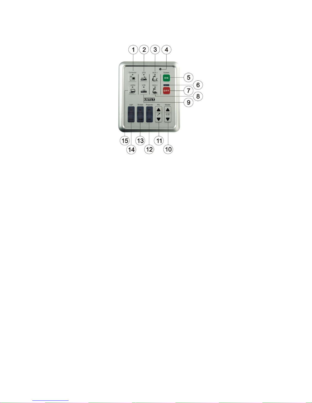
Fig. 2
1) Computer.
Pressing this button enables you to select the computer input. The LED will light if the computer input is
selected.
2) DVD.
Pressing this button enables you to select the DVD input. The LED will light if the DVD input is selected.
3) Aux 1.
Pressing this button enables you to select the Aux 1 input. The LED will light if the Aux 1 input is
selected.
4) IR receiver.
Use in combination with an infrared remote control.
5) System ON.
If the button is pressed, the system will turn on the power supply for other connected devices. By
factory preset the device will turn on the aux power socket, the projector power socket, the amplifier
power socket, lower the projection screen and dim the light in the room in sequence. After a
programmable amount of time, the projector will start up. While starting up, the system indication
LED’s will blink alternately.
6) System indication LED’s
7) System OFF.
If the button is pressed, the system will send a stop code to the projector via the control interface,
hoist up the screen, and cut off the power supply to the amplifier and other devices in sequence. The
projector will stop after a programmable amount of time.
8) Aux 2.
Pressing this button enables you to select the Aux 2 input. The LED will light if the Aux 2 input is
selected.
9) VCR.
Pressing this button enables you to select the VCR input. The LED will light if the VCR input is selected.
10) Master volume control.
Press the ▲ button to increase the volume. Press the ▼ button to decrease the volume.
11) Mic volume control.
Press the ▲ button to increase the volume. Press the ▼ button to decrease the volume.
12) Projector On/Off.
Pressing these button switches the (external) projector on or off.
13) Screen Up/Down.
Pressing these buttons allows you to remotely move an external screen up or down.
Page 9
7
14) Light Up/Down.
Pressing these buttons let’s you control an external dimmer by means of an analog
control voltage (DC 0-10V).
15) Laptop.
Pressing this button enables you to select the Laptop input. The LED will light if the Laptop input is `
selected.
Front
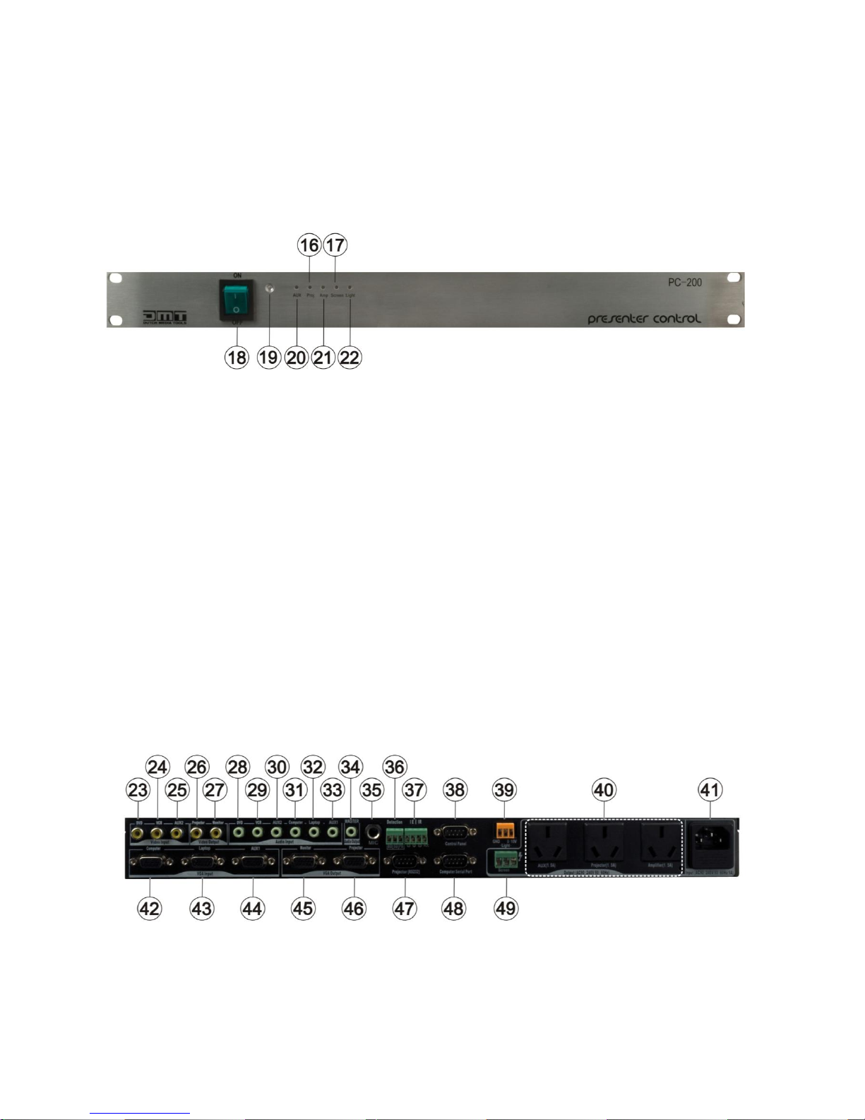
Fig. 3
16) Projector power indicator.
Lights up if the Projector socket is active.
17) Screen down indicator.
Lights up if the screen is lowered down.
18) Power switch.
Use to turn the system on or off.
19) Power LED.
Indicates that the unit is turned on.
20) Aux power indicator.
Lights up if the Aux socket is active.
21) Amp power indicator.
Lights up if the Amp socket is active.
22) Light intensity indicator.
The Presenter Control can send a control voltage (DC 0 – 10V) to an external dimmer. The intensity of
the LED is linear with the DC voltage at the light output.
Backside
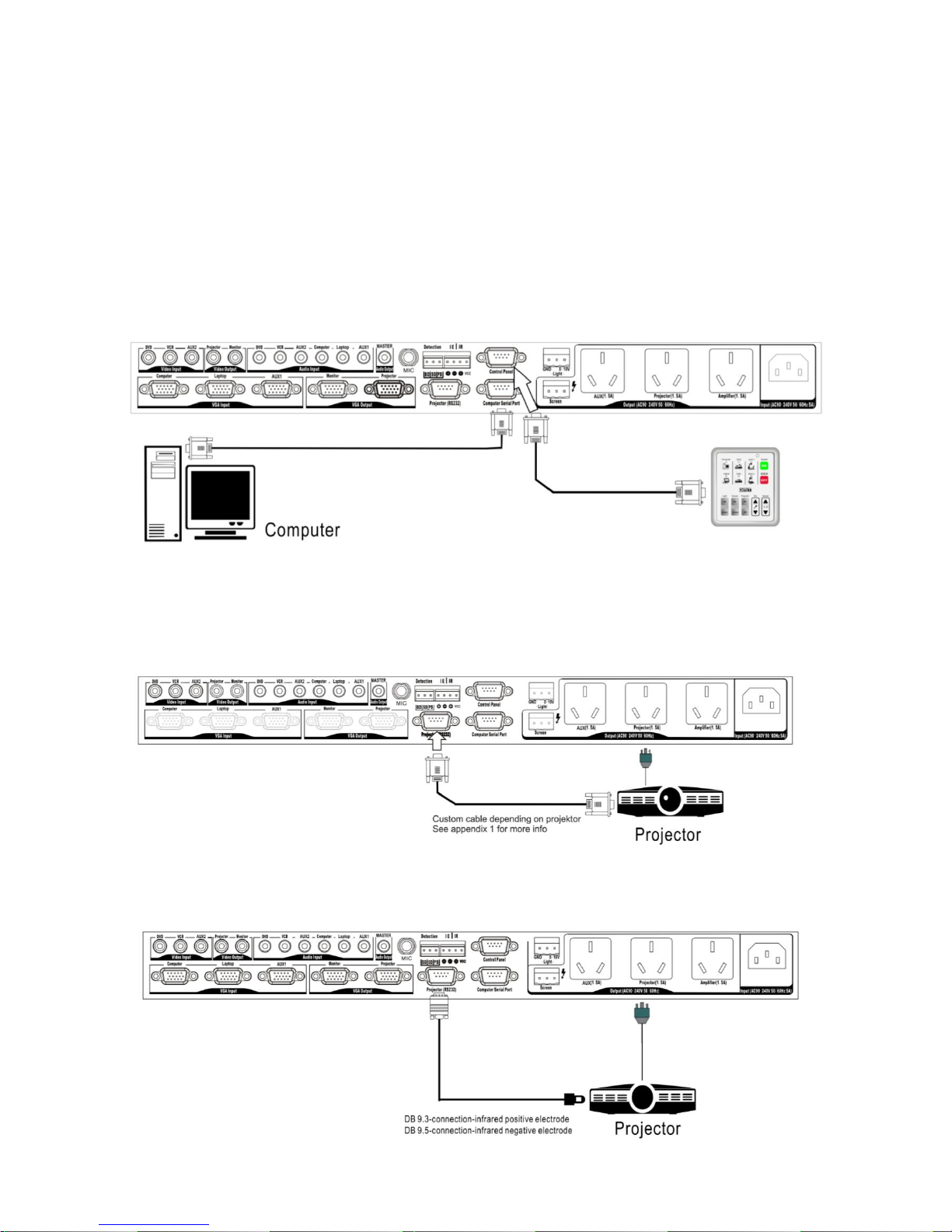
Fig. 4
23) DVD video input.
Connect with S-video Out terminal of a S-video device.
24) VCR video input.
Connect with the Audio Out terminal of a S-Video/YCbCr device.
Page 10

8
25) Aux 2 video input.
Connect with Video Out terminal of a video device.
26) Projector video output.
This output will contain the video program signal.
27) Monitor video output.
This output will continuously show the DVD output. This way the operator has a preview facility to find
the desired program material on the DVD player.
28) DVD audio input.
Connect with the Audio Out terminal of a DVD device.
29) VCR audio input.
Use the supplied adapter only.
30) Aux 2 audio input.
Connect with the audio output of a line level audio device.
31) Computer audio input.
Connect with the audio output of a PC/ laptop.
32) Laptop audio input.
Connect with the audio output of a PC/ laptop.
33) Aux 1 audio input.
Connect with the audio output of a line level audio device.
34) Master audio output.
Connect with your mixer or amplifier.
35) Mic audio input.
Jack input. Level can be adjusted by using the MIC Volume Control buttons (11).
36) Detection terminal.
Use this input to connect door switch detectors.
37) IR LED terminal.
Use to connect an Infrared LED for remote purposes.
38) Control panel
9-pole Sub D connector for connecting the control panel.
39) Light control
Control Voltage output for remote light control (0-10V).
40) Switched power sockets
Used for remote controlling of external devices.
41) IEC inlet
42) Computer VGA input.
Connect to the VGA output of a PC/ laptop. Because this input takes the computer’s VGA signal,
The computer’s monitor should be connected to the monitor VGA output (45).
43) Computer Laptop VGA input.
Connect to the VGA output of a PC/ laptop.
44) Aux 1 VGA input.
Connect to the VGA output of a PC, laptop or other VGA compatible device.
45) Monitor VGA Output.
Connect with the VGA in terminal of a monitor. This output will continuously show the computer’s VGA
signal.
46) Projector VGA Output.
Connect with the VGA in terminal of a projector. This output will contain the VGA program signal.
47) Projector RS232 terminal.
Connect with the RS232 terminal of a projector.
48) Computer serial port.
Connect with the RS232 port of your PC/ laptop to program the Presenter Control.
Page 11
9
Installation
Remove all packing materials from the Presenter Control. Check that all foam and plastic padding is
removed. Connect all cables.
Set up examples
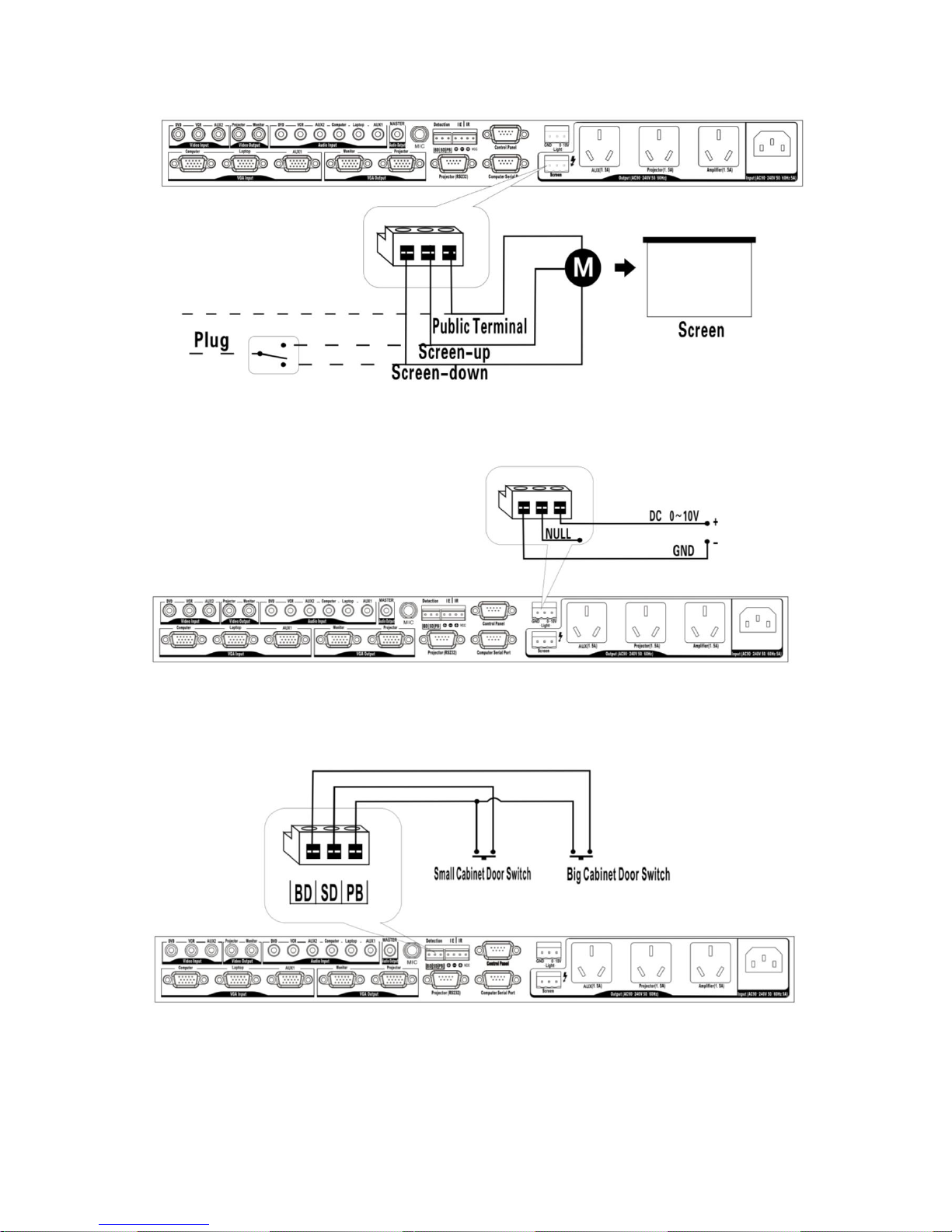
Programming the device
1. Connect the Computer serial port (48) on the rear panel of the Presenter Control with the
corresponding serial port of your PC/ Laptop using the supplied programming/ communication cable.
2. Connect the Control Panel Port (38) of the Presenter Control with the 9-pin port of the Control Panel
using the supplied programming/ communication cable.
Fig. 5
Controlling a projector with the Presenter Control using the remote terminal
Use a suitable cable between presenter control and projector. For pinning of the Presenter control
connector see appendix 1.
Fig. 6
Controlling a projector with the Presenter Control using IR
Fig. 7
Page 12
10
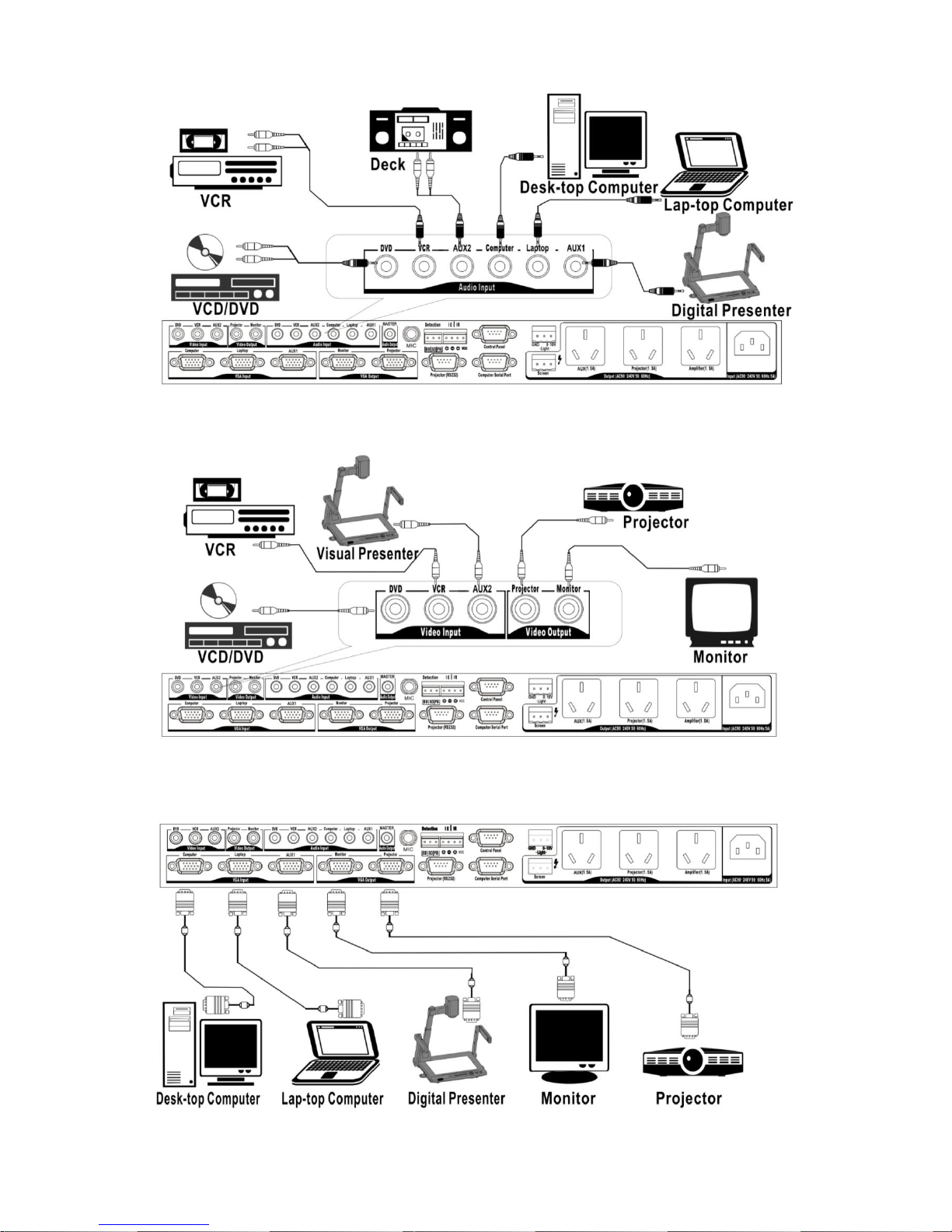
Controlling an electric Projection screen with the Presenter Control
Fig. 8
Light control with the Presenter Control
Fig. 9
Switch detection with the Presenter Control
Fig. 10
Attention:
1. Switches have to be NC types. They must be closed when the door is closed.
2. If the “small door” switch is not used. Short the input.
3. If the “Big door” is opened, the unit ignores the “small door” switch.
Page 13
11
Connecting audio equipment with the Presenter Control
Fig. 11
Connecting video equipment
Fig. 12
Connecting VGA equipment
Fig. 13
Page 14
12
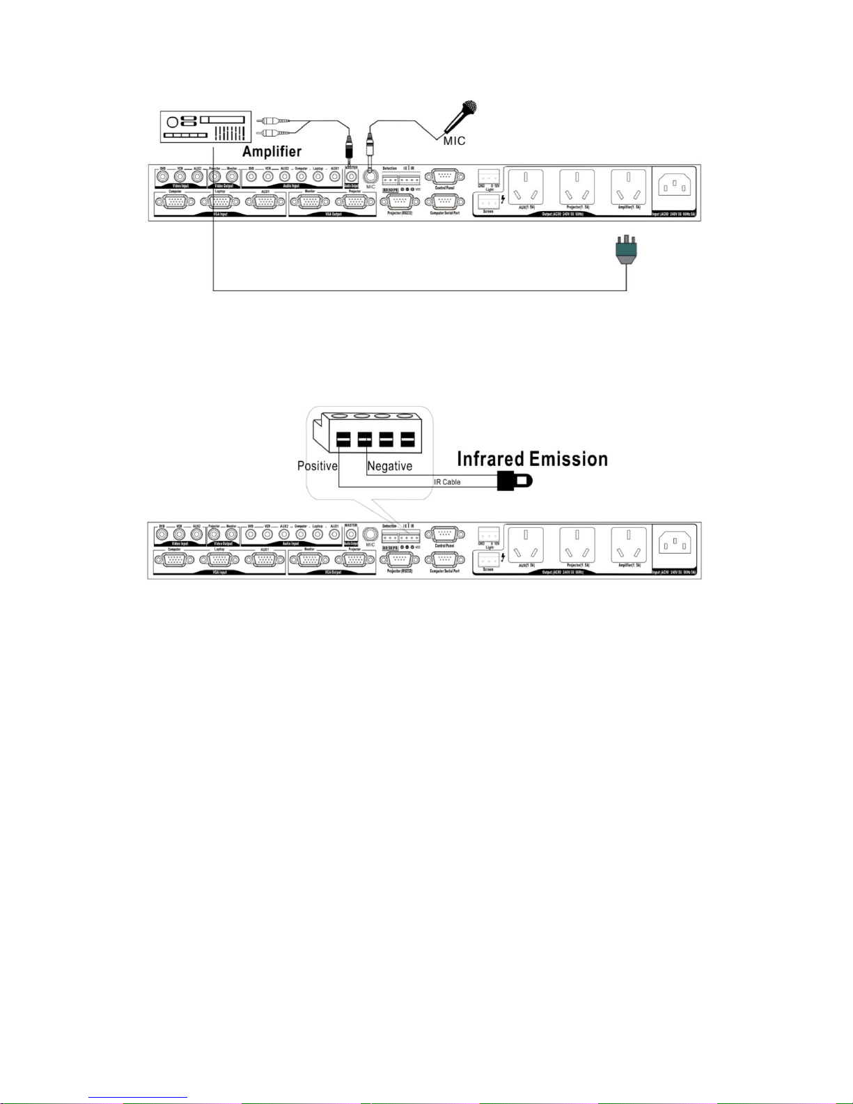
Mic input and audio output
Fig. 14
Infrared transmission
Connect the supplied IR LED to the terminal. Be sure to check the polarity of the LED. (white = +,
black = -). Attach the LED to the receive window on the device to be controlled.
Fig. 15
Page 15
13
Software Installation
If you wish to use the automation or remote functions Host, please install the Presenter control Setup
Program.
Minimum system requirements:
Intel Pentium 200Mhz or up.
Windows 2000/ XP.
128M Memory.
30Mb Hard Disk.
Attention: Presenter control software is compatible with WIN2000/XP. The program may not function
properly under other operating systems.
Installation procedure:
Be sure to turn off the power supply to all equipment as well as the computer.
Please connect the random communication/ programming cable to the RS232 port of the
computer and the Host.
Turn on the power supply to the host and the computer.
Insert the CD-ROM into the computers CD-drive and follow the instructions.
Running the setup program.
Run the setup wizard program.
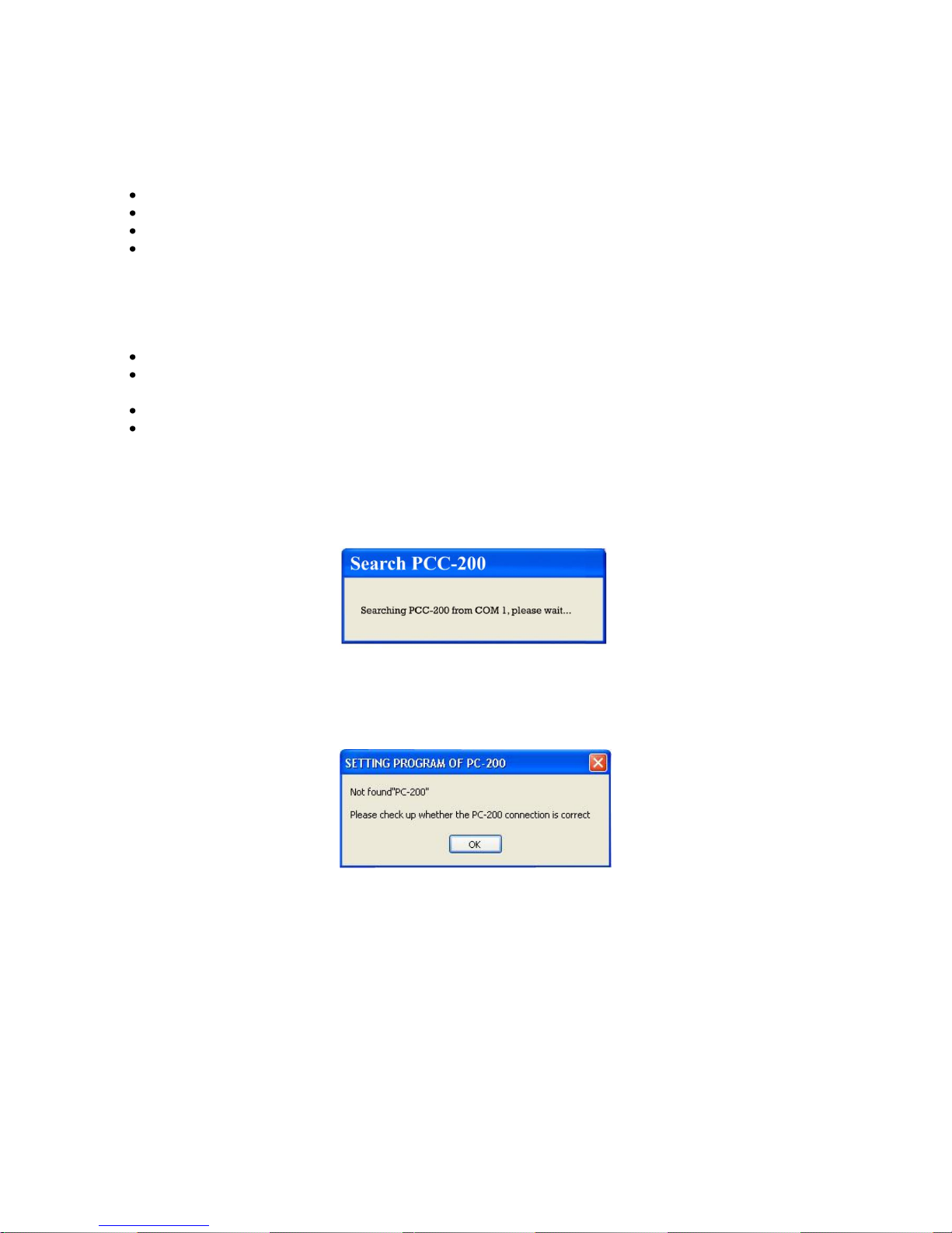
The computer will start searching for the Presenter Control and the window shown in figure 5 will appear.
Fig. 16
If the computer fails to find the Presenter Control, the window shown in Figure 6 will appear.
Fig. 17
Page 16
14
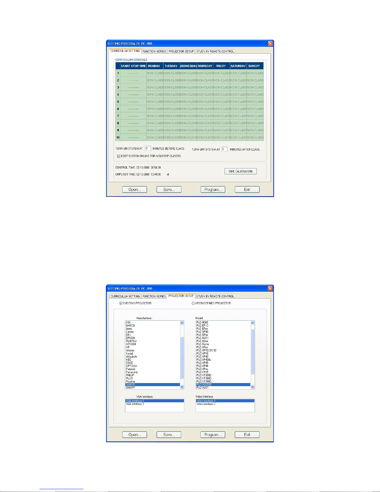
If the connection is set up properly, the setup program will start the main interface (figure 18).
Fig. 18
Curriculum schedule
The first tab is called Curriculum Schedule. Use this tab to automate your Presenter Control. You can
program the Presenter Control to start up and shut down (according the sequence referred to on page
6). You can program up to 10 events each day.
Projector setup
After selecting the projector setup tab, following window will appear.
Fig. 19
Page 17
15
First check if your projector is listed in the Existing projector list, if so please select the desired projector
and click the icon “programming”. Now the setup program will transmit the right RS232 code to the Host.
If your projector is not in the list, you have to setup the control protocol yourself, using the projectors
information.
Presenter control will support Projectors which are controlled by either serial port or IR-remote control.
Please refer to your projectors operating manual or consult your dealer for the right control code.
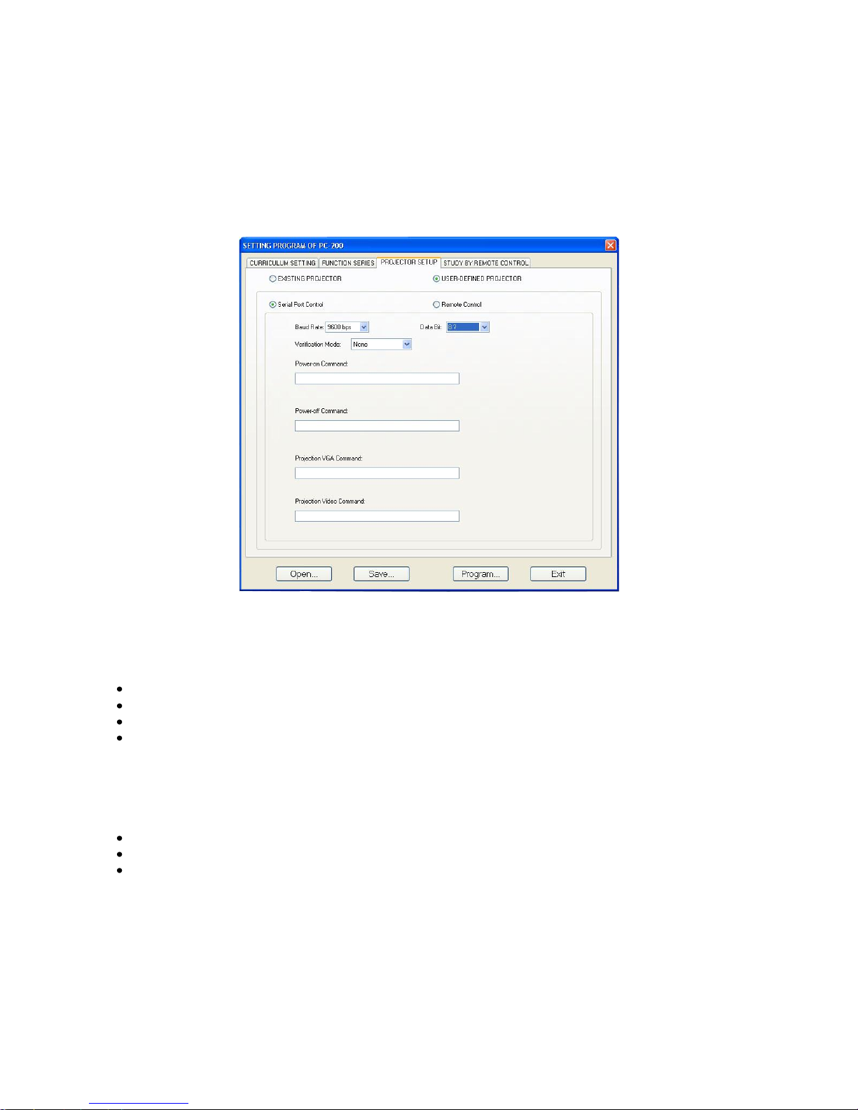
Serial port Control
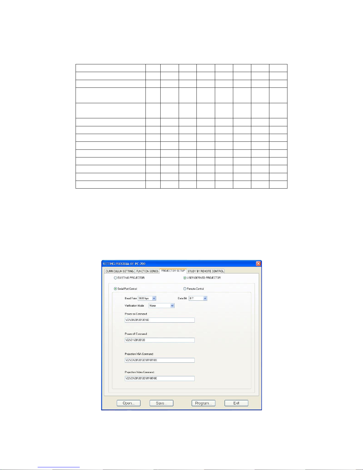
First select “USER-DEFINED PROJECTOR”. Now the window shown in figure 20 will appear.
Fig. 20
Click “serial Port Control” after confirmation. Now the communication parameters will be identified in
advance.
Baudrate
Data number of bits: 7 bits or 8 bits.
Stop Bit: 1 bit.
Verification Mode: none, even, odd, space, mark.
Please look up the projectors parameters carefully in the projectors manual. If you’re not sure contact
your dealer.
Requirements for the RS232 code.
Use hexadecimal digits only. Please transform other codes to the Hexadecimal format.
The symbol “\” is necessary for separating the Hex-digits.
Special characters have to be transferred into Hexadecimal digits also. Use a ascII table for
special characters. E.g. Blank-space is “20”, the line feed character is “0A” and enter character is
“0D”.
Page 18
16
Example 1
Projector Code:
Communication agreement
Baudrate : 9600bps
Databit : 8
Verification Mode: None
Stopbit : 1
Now the following parameters should be entered in the window as shown in figure 21.
Fig. 21
Power on
02H
00H
00H
00H
00H
02H
Power off
02H
01H
00H
00H
00H
03H
Input select RGB
02H
03H
00H
00H
02H
01H
01H
09H
Input select DVI
(analog)
02H
03H
00H
00H
02H
01H
02H
0AH
Input select DVI
(digital)
02H
03H
00H
00H
02H
01H
1AH
22H
Input select video
02H
03H
00H
00H
02H
01H
06H
0EH
Input select S-video
02H
03H
00H
00H
02H
01H
0BH
13H
Input select vieuwer
02H
03H
00H
00H
02H
01H
1FH
27H
Picture mute on
02H
10H
00H
00H
00H
12H
Picture mute off
02H
11H
00H
00H
00H
13H
Sound mute on
02H
12H
00H
00H
00H
14H
Sound mute off
02H
13H
00H
00H
00H
15H
On screen mute on
02H
14H
00H
00H
00H
16H
On screen mute off
02H
15H
00H
00H
00H
17H
Page 19
17
Example 2
Power-on command of the projector is POWR___1 (Enter)
(_ signifies space)
Then in the command field should contain: \50\4f\57\52\20\20\20\31\0d (upper/lower case is
insensitive).
Also see the ACII table in appendix 3.
Infrared remote control
If it is impossible to obtain the Control Code of a projector, but the projector can be controlled by
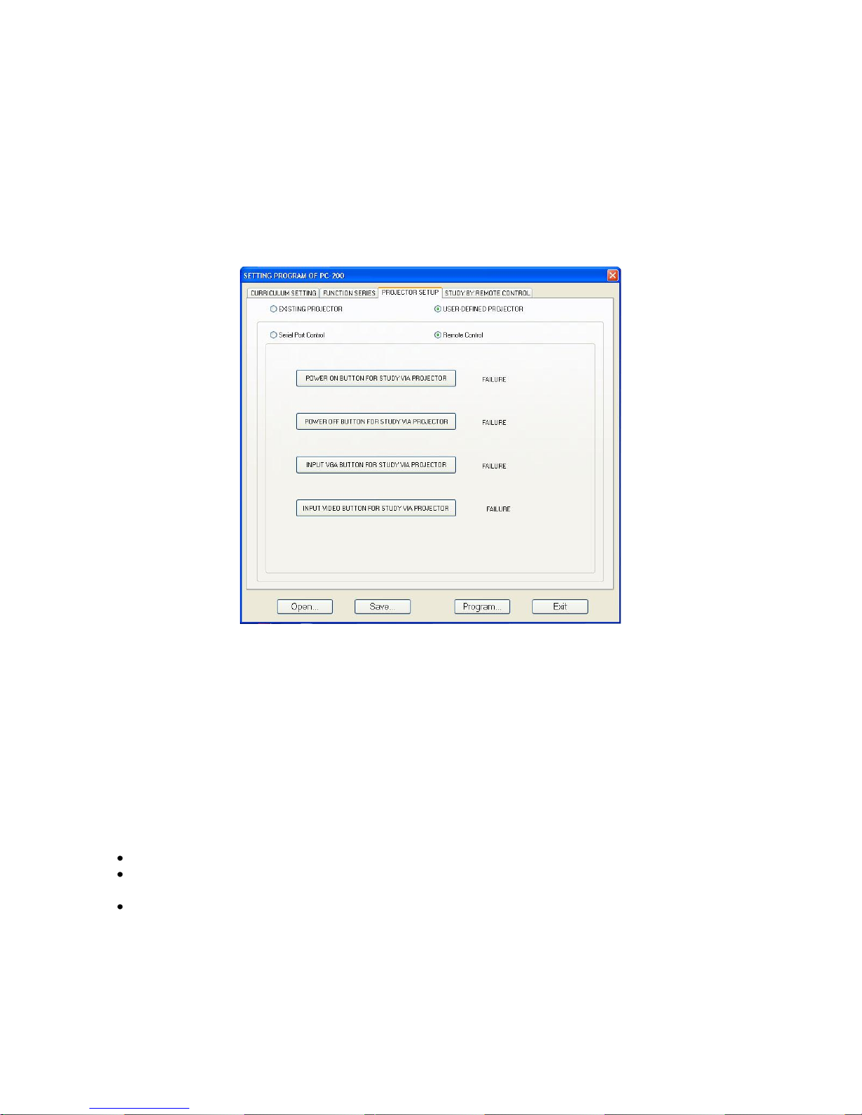
infrared control, please select the “Infrared Remote Control” button. See figure 22.
Fig. 22
Make an “Infrared Learning Cable” (see appendix 1) and connect the wire as shown in figure 7 on
page 9.
The system shall pickup the infrared code of the projector via infrared receiving window on the control
panel of the host.
The computer shall process the infrared code and send out the infrared signal to the infrared receiving
window of the projector through the infrared LED, connected to the wire. You can observe the action of
the projector to verify the correctness of the infrared code.
Please note the following :
Construct an Infrared learning cable according the figure in appendix 1.
The infrared diode should be connected to pins 3/5 and correspond with Anode (+) and
Cathode (-) respectively.
Please place the Infrared LED next to the Infrared receiving window of the projector.
Attention
Please confirm that the power supply of the projector is kept on during the infrared study.
Before executing a certain function, confirm that the projector is ready to receive infrared signals.
After confirmation of the correct connection, turn on the computer and run the setup program to reach
the screen shown in figure 22. Aim the remote control of the projector at the receiving window of the
Page 20
18
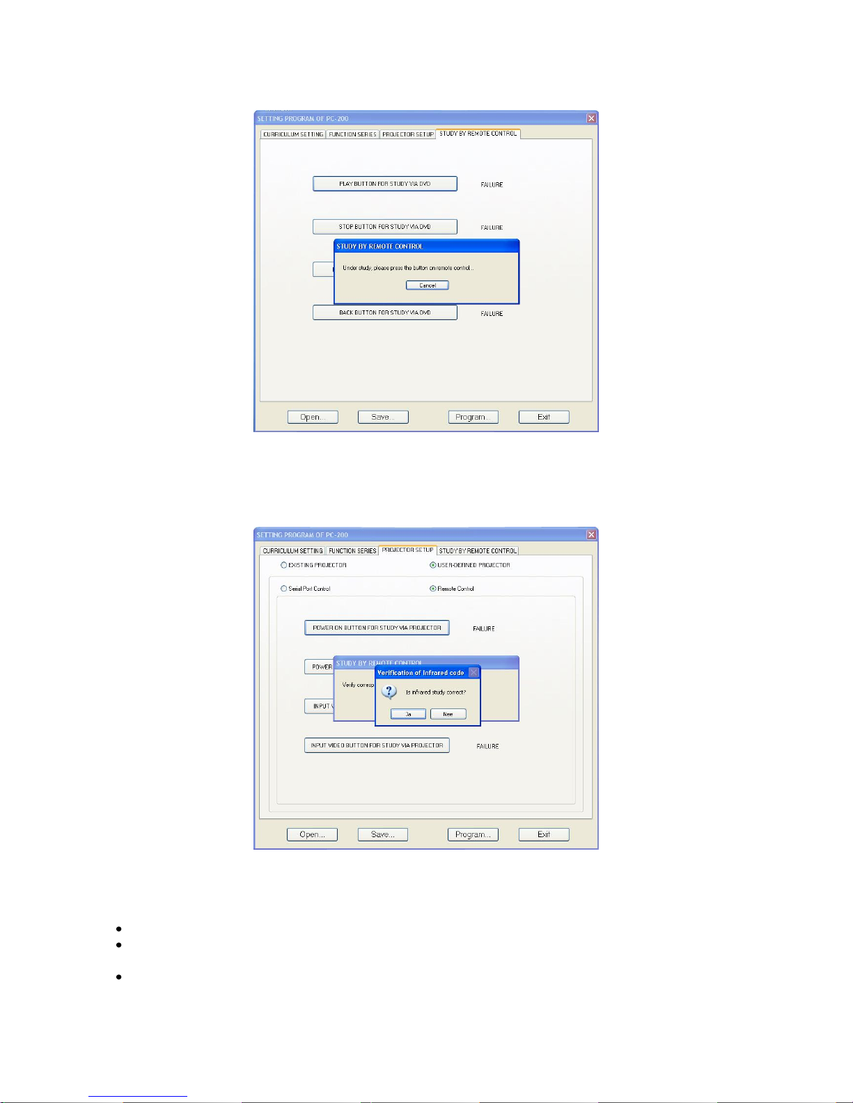
host’s control panel. Press the corresponding software button (for the infrared function to study), The
setup program will start a window for the button you pressed. See figure 23.
Fig.23
Now, press the corresponding button on the projector’s remote control. After successful sampling of the
infrared code, a pop up window shall appear asking you to confirm. Therefore, please check the
projectors action. If ok, then confirm. If not ok, press “No” and start all over again.
Fig. 24
Possible causes for problems during infrared learning mode
Check the connections of the learning cable.
Check if the infrared LED is correctly placed next to the infrared receiving window of the
projector.
Incorrect sampling of infrared code. Try again and check the projector’s action.
Let the host learn each function in sequence.
Page 21
19
DVD IR remote control
It is possible to control a DVD player with your Presenter Control by using it’s infra red remote control. Just
like with a projector as described in the former chapter.
1. Connect the IR LED to the IR LED terminal (37) as shown in figure 15 on page 12.
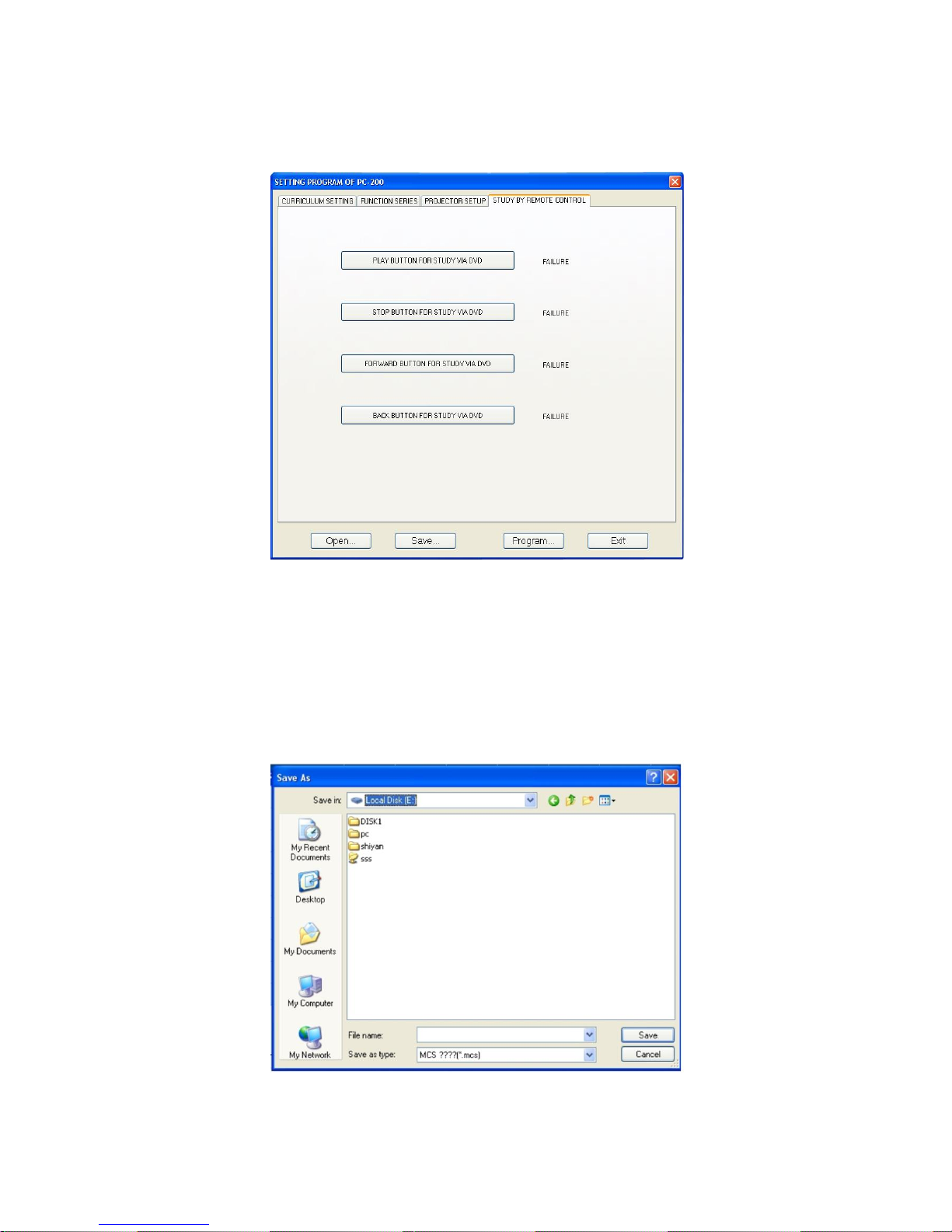
2. Select the “Study by remote control” tab. Now a window as shown in figure 25 will pop up.
Fig. 25
Proceeding is similar to the projector set up with remote learning function.
Saving the setup.
Please save the data for future maintenance or transform the data to those Hosts which have a similar
configuration. See Figure 26. It is therefore wise to save the setup using a filename that includes the
projector’s name or model number.
Fig. 26
Page 22
20
Sending the program to the Host.
Connect the programming cable, check if connected properly and click the “programming” button.
Now the data will be send to the host. The transmission speed shall be shown in the transmission process.
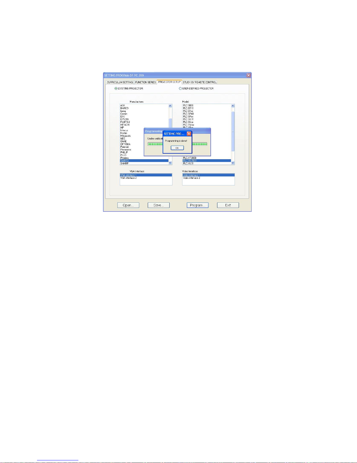
When programming is completed successfully, the Presenter control will restart automatically. A pop-up
window as shown in Figure 27 will appear. Confirm and the setup program will be closed.
Fig. 27
Maintenance
The DMT Presenter Control requires almost no maintenance. However, you should keep the unit clean.
Disconnect the mains power supply, and then wipe the cover with a damp cloth. Do not immerse in
liquid. Do not use alcohol or solvents.
Keep connections clean. Disconnect electric power, and then wipe the connectors with a damp cloth.
Make sure connectors are thoroughly dry before linking equipment or supplying electric power.
Troubleshooting
This troubleshooting guide is meant to help solve simple problems. If a problem occurs, carry out the steps
below in sequence until a solution is found. Once the unit operates properly, do not carry out following
steps.
The indication lamp on the control panel is not illuminated.
1. If the device does not operate properly, unplug the device.
2. Check power from the wall, all cables, the fuse, etc.
3. If all of the above appears to be O.K., plug the unit in again.
4. If nothing happens after 30 seconds, unplug the device.
5. Return the device to your DAP Audio dealer.
The projector is uncontrollable.
Possible causes:
1. The control code of the projector is not right. (please restart the setup program).
2. The communication cable is not connected to the projector appropriately. (Please check if the pins of
the communication cable are soldered correctly and according the diagram in appendix 1).
Page 23
21
Interference on projection screen.
Possible causes:
The power supplies for the projector and other equipment don’t share common ground.
Product specification
Power supply: AC 90-230V - 50-60Hz
Signal inputs:
Video: (RCA) 3 lines
RGB signal: 3 lines
Audio: 6 stereo lines (3,5 mm jack)
1 mic (6,35 mm jack)
Signal outputs:
Video: (RCA) 2 lines
RGB signal: 2 lines
Audio: 1 stereo line (3,5 mm jack)
Control inputs: RS-232 interface: 2 lines
Control panel interface: 1 line
Door detection: 2 lines
Remote control interface: 1 line
Infrared interface: 1 line
Power supply connection:
Electric screen: 1 line
Lighting system: 1 line
Projector: 1 line
Amplifier: 1 line
AUX: 1 line
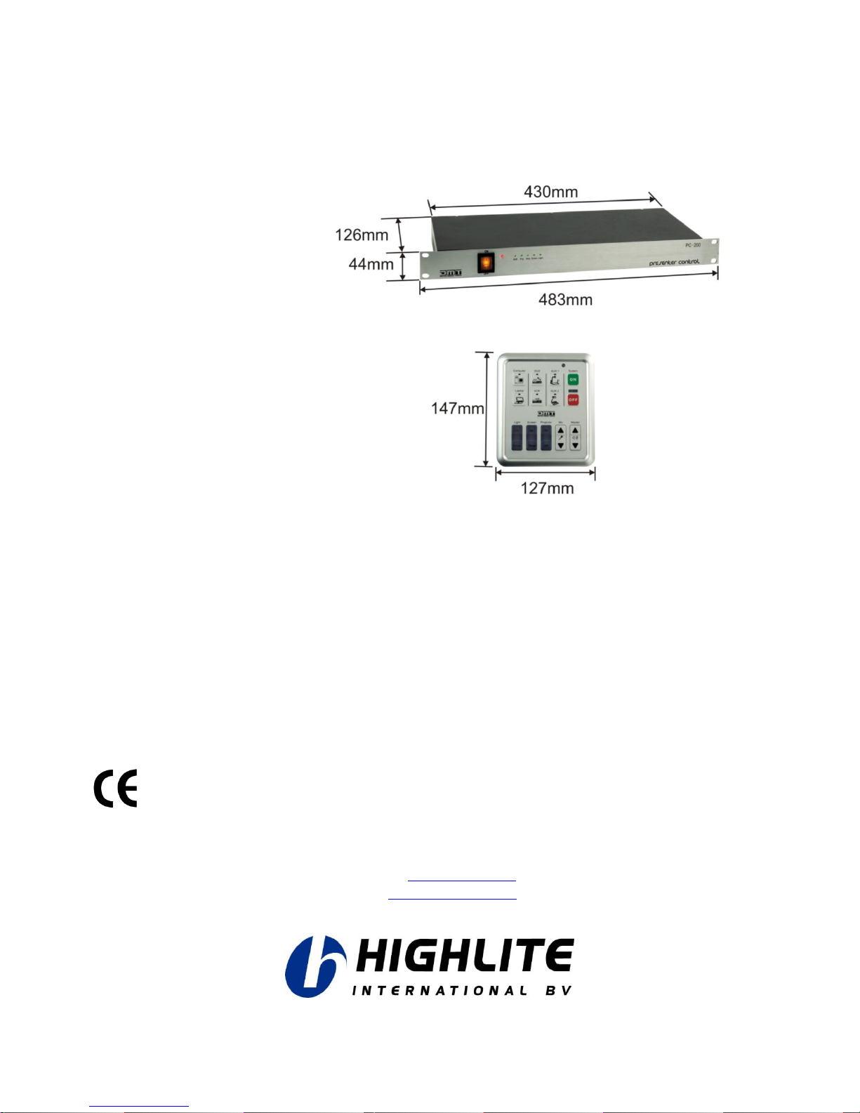
Dimensions: 483 x 216 x 44 mm (LxWxH)
(main unit)
Dimensions: 147 x 127 mm (LxW)
(control unit)
Design and product specifications are subject to change without prior notice.
Website: www.Highlite.nl
Email: [email protected]
Page 24
22
Appendix 1: Pin definition of programming cable, Infrared learning cable and
projector remote cable.
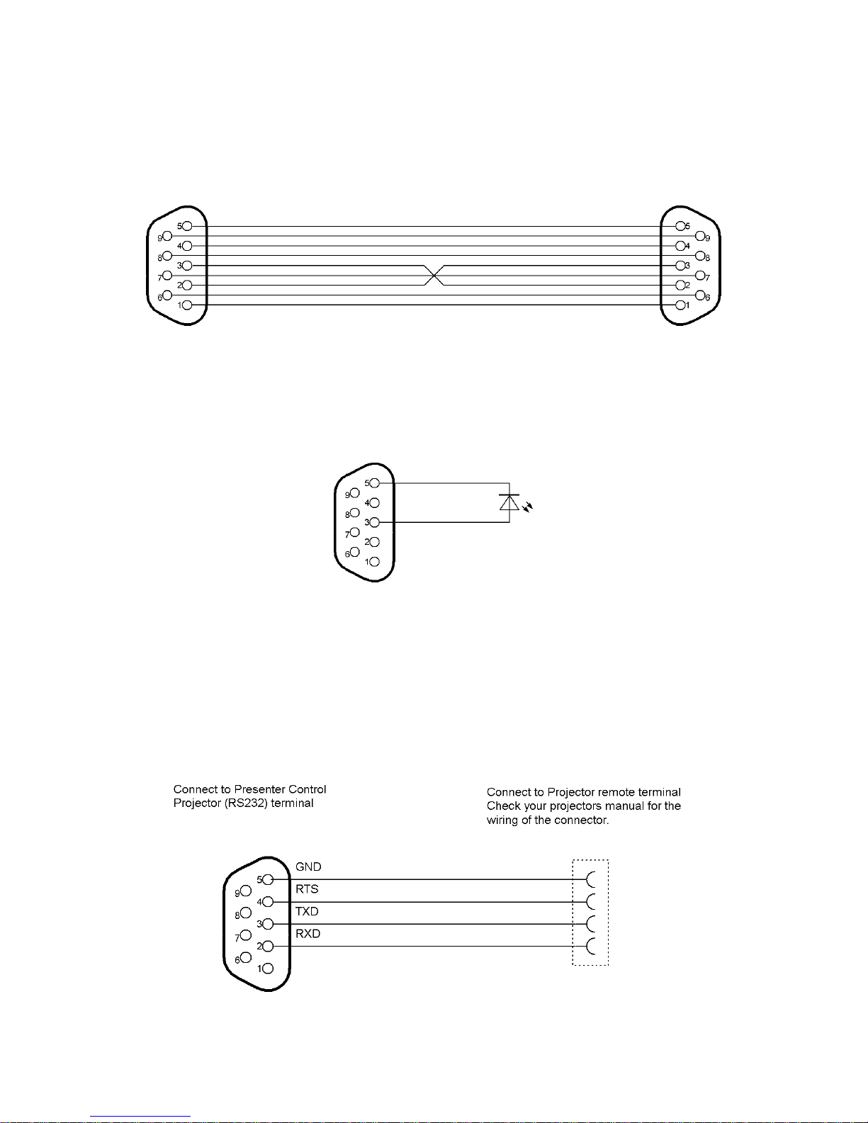
Programming cable.
Fig. 1
Infrared learning cable.
Fig. 2
Projector remote cable.
This cable depends on the remote connector of your projector. This cable has to be bought separately or
custom made.
The projector RS232 terminal (47) connections are shown in fig. 3.
Fig. 3
Page 25
23
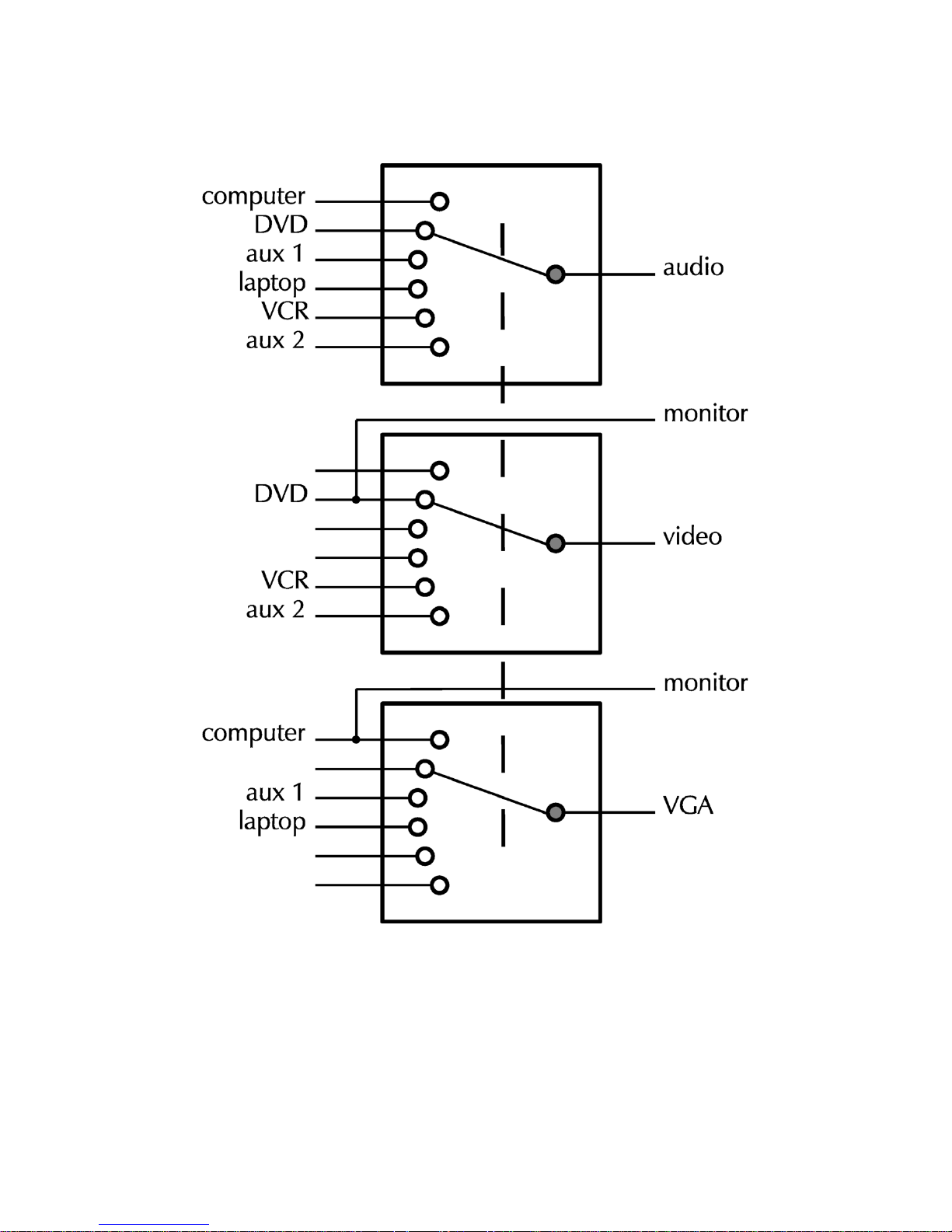
Appendix 2: Block diagram of the Multimedia centralized control system.
Page 26

sign hex. code sign hex. code sign hex. code sign hex. code sign hex. code
null 0 7 37 n 6E ¥ A5 Ü DC
start of heading 1 8 38 o 6F ¦ A6 Ý DD
start of text 2 9 39 p 70 § A7 Þ DE
end of text 3 : 3A q 71 ¨ A8 ß DF
end of transmit 4 ; 3B r 72 © A9 à E0
enquiry 5 < 3C s 73 ª AA á E1
acknowledge 6 = 3D t 74 « AB â E2
audible bell 7 > 3E u 75 ¬ AC ã E3
backspace 8 ? 3F v 76 AD ä E4
horizontal tab 9 @ 40 w 77 ® AE å E5
line feed 0A A 41 x 78 ¯ AF æ E6
vertical tab 0B B 42 y 79 ° B0 ç E7
form feed 0C C 43 z 7A ± B1 è E8
carriage return 0D D 44 { 7B ² B2 é E9
shift out 0E E 45 | 7C ³ B3 ê EA
shift in 0F F 46 } 7D ´ B4 ë EB
data link escape 10 G 47 ~ 7E µ B5 ì EC
device control 1 11 H 48 • 7F ¶ B6 í ED
device control 2 12 I 49 € 80 · B7 î EE
device control 3 13 J 4A • 81 ¸ B8 ï EF
device control 4 14 K 4B , 82 ¹ B9 ð F0
neg. Acknowledge 15 L 4C ƒ 83 º BA ñ F1
synchronous idle 16 M 4D „ 84 » BB ò F2
end transm. block 17 N 4E … 85 ¼ BC ó F3
cancel 18 O 4F † 86 ½ BD ô F4
end of medium 19 P 50 ‡ 87 ¾ BE õ F5
substitution 1A Q 51 ^ 88 ¿ BF ö F6
escape 1B R 52 ? 89 À C0 ÷ F7
file separator 1C S 53 Š 8A Á C1 ø F8
group separator 1D T 54 ‹ 8B Â C2 ù F9
record separator 1E U 55 Œ 8C à C3 ú FA
unit separator 1F V 56 • 8D Ä C4 û FB
space 20 W 57 Þ 8E Å C5 ü FC
! 21 X 58 • 8F Æ C6 ý FD
" 22 Y 59 • 90 Ç C7 þ FE
# 23 Z 5A Ø 91 È C8 ÿ FF
$ 24 [ 5B ø 92 É C9
% 25 \ 5C ª 93 Ê CA
& 26 ] 5D º 94 Ë CB
' 27 ^ 5E • 95 Ì CC
( 28 _ 5F À 96 Í CD
) 29 ` 60 à 97 Î CE
* 2A a 61 ˜ 98 Ï CF
+ 2B b 62 ™ 99 Ð D0
, 2C c 63 š 9A Ñ D1
- 2D d 64 › 9B Ò D2
. 2E e 65 œ 9C Ó D3
/ 2F f 66 • 9D Ô D4
0 30 g 67 þ 9E Õ D5
1 31 h 68 Ÿ 9F Ö D6
2 32 i 69 A0 × D7
3 33 j 6A ¡ A1 Ø D8
4 34 k 6B ¢ A2 Ù D9
5 35 l 6C £ A3 Ú DA
6 36 m 6D ¤ A4 Û DB
Appendix 3 ASCI-table
Page 27

20 0 8
DMT.
 Loading...