

Page 1
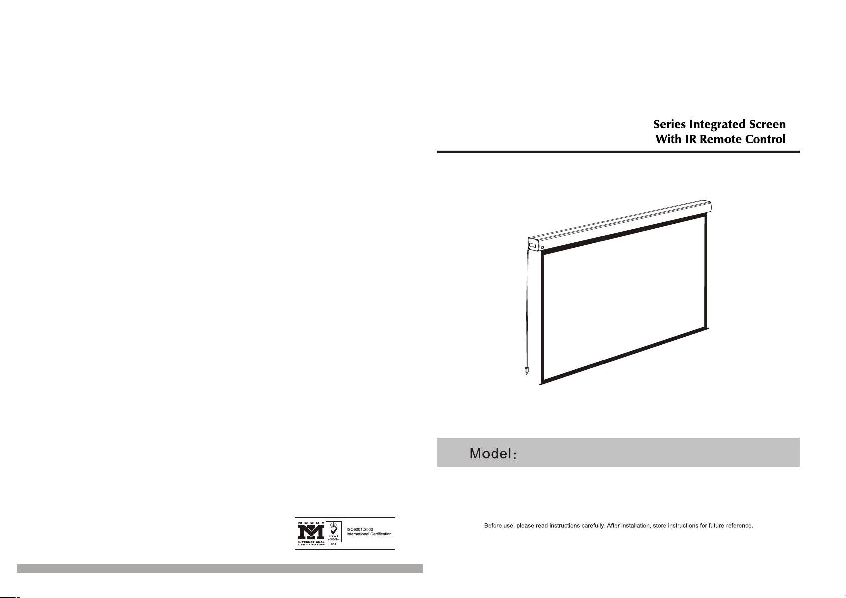
100360
Page 2
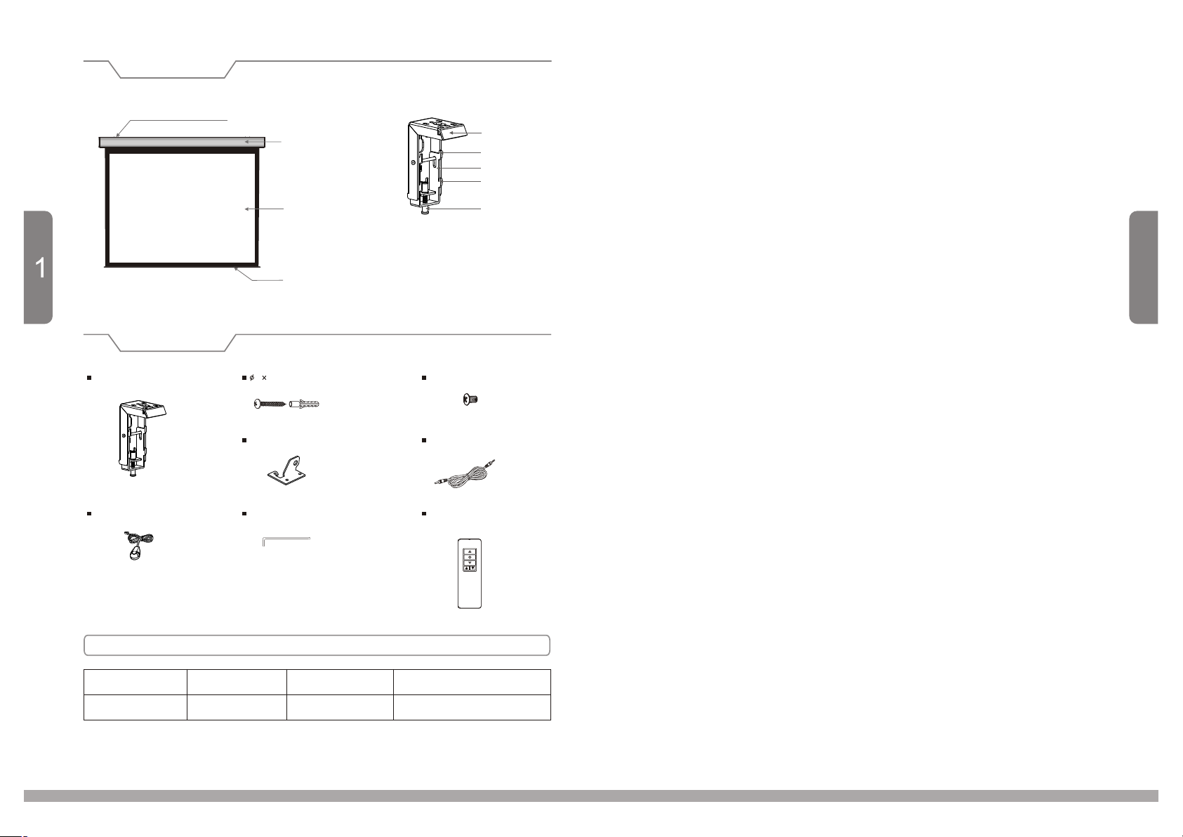
Description
Floating mounting bracket
Accessories
Floating mounting bracket (2pcs)
External IR receiver (1 )pc
Aluminum casing
Screen fabric
Bottom Rod
5 40mm Tapping screw & cap (8sets)
Ceiling hanger (2pcs)
Allen key (1pc)
Top panel
Upper groove
Locking piece
Lower groove
Locking screw
M5x10 Scre w (6pcs)
Trigger line ( 1pc )
Rem
o
t
e
Co
n
t
ro
ll
e
r
(1
Plea se r ead t he se i mpo rt ant saf et y ins tr uctio ns
Read a nd u nde rs ta nd al l in str uc ti ons b ef ore ins ta lli ng a nd usin g th e pro je ction s cr een .
Alwa ys c onn ec t th is pr oj ectio n Sc ree n to a g round ed o utl et . Th e po wer o ut let sho ul d be lo ca ted
near t he S cre en a nd s hal l be e asily a cc ess ib le.
This e qu ipm en t mu st be s up pli ed f ro m a pow er s ystem p ro vid in g a P R O T E C T I VE E A RTH
conn ec tio n an d havin g a ne utr al c on nec ti on, w hi ch c an be r el iab ly i de nti fie d.
Alwa ys e nsu re t ha t the u ni t is prop er ly ea rt hed and p ow er co nn ectio ns c orr ec tly mad e.
To reduc e th e ris k of e lectr ic s hoc k, d o no t dis as sembl e th is pr oj ectio n sc ree n, b ut take i t to a
qual ifi ed se rv ic ema n wh en se rv ic e or re pa ir is r eq ui red . In corre ct r eas se mbly ca n re sul t in
elec tr ic sh oc k wh en us ed .
Clos e su per vi si on is n ec ess ar y wh en Pr oj ectio n sc ree n is i n use by or n ea r chi ld ren. Do n ot
leav e Sc ree n un at ten de d whi le i s us e.
Inst al ler m us t en sur e th at the mo un tin g st ructu re s and f as tener s mu st be o f ad equat e st ren gt h
to sec ur ely s up po rt th e sc ree n so t ha t vib ra tions o r ev en ab us ive pul li ng on t he s creen s ur fac e
will n ot c aus e th e ho usi ng t o wor k lo os e or fa ll .
Do no op er ate s cr ee n wit h a da maged c or d or if t he s creen h as b een d ro pped or d am age d un til it
has be en e xam in ed a nd re pa ire d by a q ua lifi ed s ervic em an
DO no t pl ace or at ta ch an yt hing to m et al ca si ng or vie wi ng su rf ac e of th e sc reen.
Posi ti on co rd s o th at it w il l not be tr ip ped o ve r, pulle d or i n con ta ct with h ot s urf ac es.
pc
)
DO no t pl ug the co rd w ith w et h ands; e le ctr ic s ho ck co ul d occ ur.
Save t ho se in st ru cti on s
10
Motorized Screen Power Specifications
Voltage Frequency
230V/120V/1 00 V
50Hz/60Hz 90W/80W
Watts
Application
Applies to moto rized screen up to 120"
Page 3
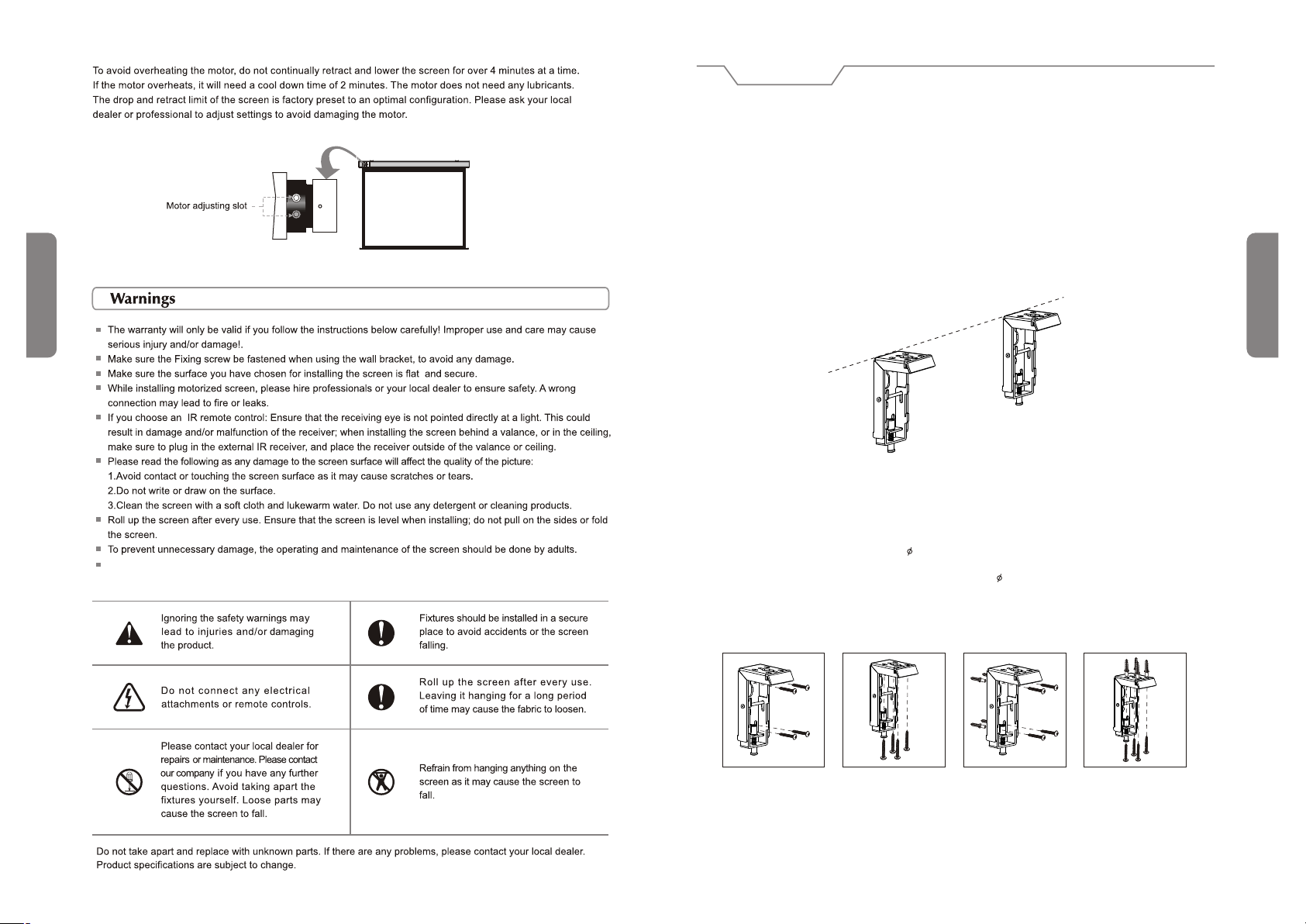
Duty c yc le :4 Mi n./30 mi n
Installation
Take out all the parts from the package and following the accessories guideline ensure all the parts are there.
There are three different types of installation available for this product: wall mount, ceiling mount or ceiling hang.
Depending on the installation environment, the floating mounting brackets can be installed at various points for your
convenience. However, the ideal position for the mounting brackets is closer to the endcap as this will reduce
vibration and noise.
Wall and Ceiling Mount Installation
1.According to the surface of installation, choose the appropriate screws needed for mounting (regular screws for
wood surfaces, tapping screws for concrete surfaces)
2.Mount the brackets onto the surface, ensuring it is level (tip: draw a erasable level line when mounting the
brackets). See below for picture description (figure 1):
9
When the plug on power cord is used as disconnect device, the socket-outlet shall be installed near the
equipment and shall be easily accessible
Figure 1
Installation Steps:
1.Wood wall and ceiling installation: Drill in the 5 x 40 screws through the appropriate holes in the bracket
(figure 2-3)
2.Drywall and ceiling installation: Install the anchors and drill in the 5 x 40 screws into the appropriate
bracket holes (figure 4-5)
Wood wall installation
Wood ceiling installation
Concrete wall installation
Concrete ceiling installation
2
Figure 2 Figure 3
Figure 4 Figure 5
Page 4
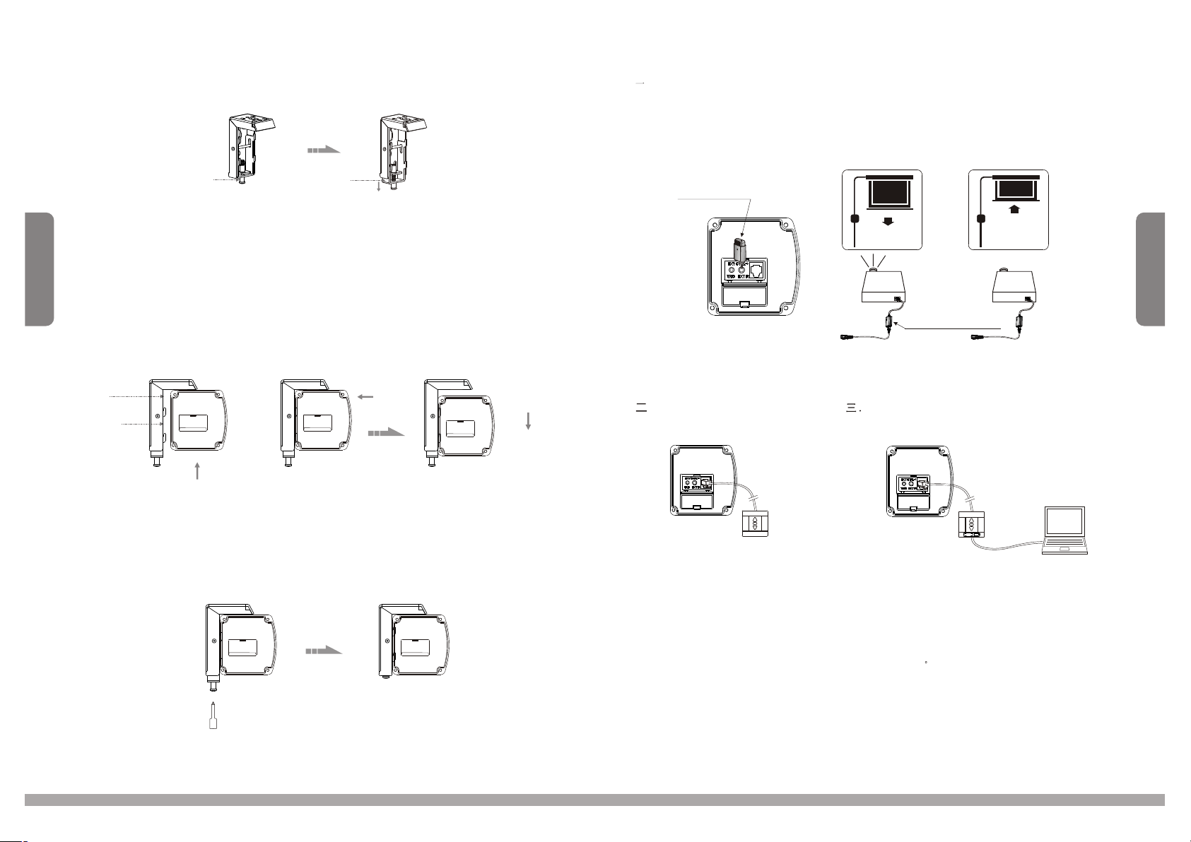
3.Loos en th e l oc kin g scre w t o l ow er the loc ki ng piece down all the way (figure 6-7)
Other Options Connection Diagram
. Function Destription for convertion from FM to I R Control
When you insert the Wireless Synchro Convertor Receiver into EXT IR plug of the screen(Figure 45), you can
use FM wireless remote control device. The Intelligent Synchro Power Supply Control Adapter(for all projectors),
with 12V wireless trigger (for projectors with trigger output), can synchronously control the screen. (Figure 46-47)
3
Locking screw
Figure 6 Figure 7
4.When mo un ti ng the scr ee n o nt o t he fl oati ng m ounting brackets, ensure the grooves on the screen
casing ma tc h u p with the up pe r and l ow er groves on the brackets. simply slide in, and the bracket’s grooves
will ho ld th e casi ng in p la ce . Hori zo ntal a djustments can still be made (figure 8-10)
Up gr oove
Down groov e
Fi gur e 8 Fi gur e 9
5.To lock t he sc re en i n pl ac e, cl os e and tighten the locking screw on the mounting brackets. This will keep
the scr ee n c as in g locke d fi rmly in pla ce (figure 11-12).
Locking piece
Figure 10
Wireless S ynchro
Convertor Receiver
Figure 45
. External Wall Switch
Figure 48
Intelligent Synchro Power
Supply Control Adapter
Figure 46 Figure 47
Externa l In tel ligent Wall Swi tch Con nec tio n
Figure 49
8
Figure 11
Figure 12
Manual control for screen up/stop/down.
Intelligent control for screen up/stop/down when
connected to the intelligent interface of the screen.
Intelligent control for screen up/stop/down when
connected to the computer's RS232 or US B
interface
Page 5
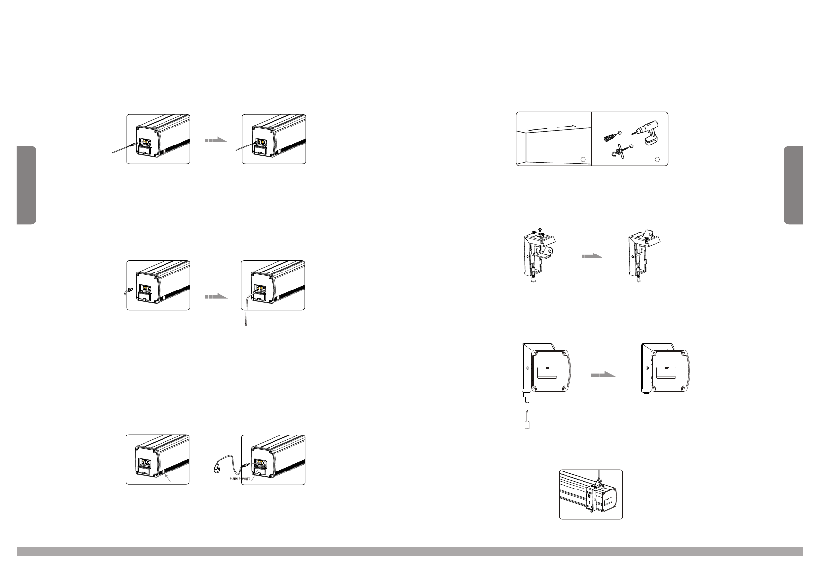
Automatic Trigger Control Description
1.Insert one end of trigger into the trigger jack at left side of screen's end cap TRIG (Figure 22),, and insert another
end into 12V output hole.
2.When the projector is running, screen fabric will go down automatically; when the projector is closed, screen fabric
will retreat automatically.
3.You can remove the 12V trigger wire if there is no need.
Ceiling Hang Installation
Choo se t ap pi ng s crews w it h ha ng er s (or o th er s cr ew s with ha ng er s, n ot p rovid ed ) ac co rd ing to yo ur
ceil in g ma te ri al. 5 x 40m m fo r wo od c ei lin gs a nd t ap pi ng scre ws f or c on cr ete cei li ng s ar e re com me nd ed .
1.Dr il l tw o id en tical h ol es w it h an e lec tr ic al d ri ll and en su re i t is h or izont al w it h th e
Wal l. F as te n hange rs ( no t pr ov ided) i nt o th e ce il ing ( fig ur e 13 ).
A
7
Figure 39 Figure 40
External Controls (Central Control or RS232, Wall Switch) Function
Plug one side of the signal cord into the computer output jack at left side of the screen's end cap, the other side of
the singal cord to the Central Control jack, RS232 or Wall Switch (Figure 41-42), and then you can
control the up/stop/down of the screen via central control or computer.
Figure 41 Figure 42
IR Remote Control Function
1.When nothing blocks the sight of IR window, you can use the controller to control the screen (Figure43).
2.For hidden installation or IR window is blocked by something, please take out the External I R Receiver and plug
its head to the revelant hole, and then fix it at the position where IR signal is available. (Figure 44)
1
Figure 13
2.Use the M5 x 10 screws provided in the accessory package to fix the ceiling hanger into the wall bracket.
Ensure the tightening screws on the wall bracket are tightened and secure. (figure 14-15)
Figure 14 Figure 15
3.After inserting the ceiling hanger, ensure the grooves on the case housing match up with the mounting
bracket. To secure the case housing into the brackets, tighten the locking screws. (figure 16-17)
Figure 16 Figure 17
2
4
Exter nd IR s ensor
Figure 43 Figure 44
4.Af te r co mp le ting st ep s 2 an d 3, c he ck to see w he th er t he w all b ra ck et i s se curel y fix ed o nt o th e housi ng
of the s cr ee n be fo re hang in g. H an g sc reen as s ho wn b el ow. (figu re 1 8)
Figure 18
Page 6
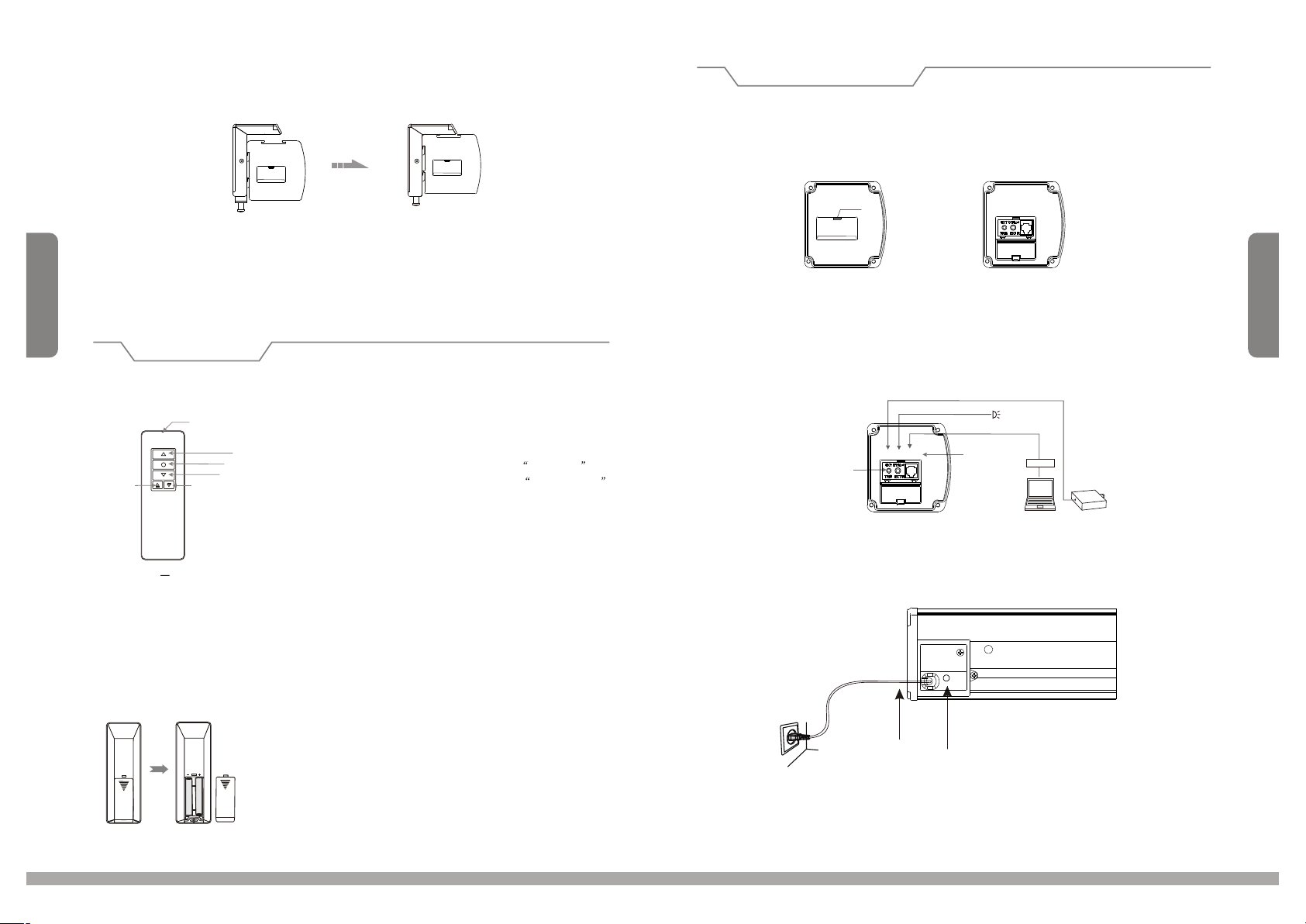
5. Fasten th e Fixi ng screw on t he bra cket, to fix tightly ont o the brackets. ( Figu re 33-34 )casing
Figure 33
Operating Instructions
Function Description
Press down and open the end cap door before using the control interface. Cover up the door if you do not need the
external function.
End cap lid
Figure 34
5
Refer to Pa ge 3 fo r Sus pen sio n han gin g.
Instructions
Controller button instruction
1.To raise screen press "UP.
2.To hold screen at desired position press STOP.
3.To lower screen press DOWN.
UP
STOP
4. To raise the screen little at your desired position press MICRO-UP
DOWN
5. To lower the screen little at your desired position press MICRO-DOWN
Caution:
The shortest distance between receiver and controller is 0.5 meter.
1.
.Controller work within 30 degree away horizontallyfrom the center of receiver
2 will
point within 8 meters fromthe screen.
.The controller not work the signal wascoveredby something.
3 will if
.Keep the controller far away from high temperatureandhumid situation.
4
.Please change the battery when the signal is weak.
5
.Please take the battery out if the controller was notbeing used for long time.
6
.Please choose the same type battery as original supplied.
7
How to insta ll the b attery:
1.Turn t he contro ller a round, push to op en the cover as gui de arr ow.
2.Put the ba tter y in according th e guide of cathod e and an ode.
3.Close th e cove r.
MIC RO-UP
1G D IR an
LED
remote c ontroller
MICR O-DOW N
"
" "
" "
Figure 35 Figure 36
How to use the Manual/Remote Control Switch Button (Figure 20-21)
This motorized screen has 4 types on control options: infrared (IR) remote control, manual control, triggered control,
and external control (central control or RS232/U SB).
Connecting
Trigger Jack
External IR
Figure 37
LA N
Projector
Central controller
Manual control switch description
Power cor d
Manual Control Switch
6
Switch control follows such proirity: Down-Stop-Up-Stop-Down.
 Loading...