


A1.170907
www.anytone.net

AT-D868UV
Operating Manual
Digital DMR and Analog
UHF/VHF Two Way Radio
DMR
DIGITAL MOBILE RADIO ASSOCIATION


THANK YOU!
Thank you very much for choosing our Dual Band Digital DMR
and Analog two way radio.
This radio adopts the latest advances in technology, providing reliable
communication in today’s demanding communication environment.
This radio offers both DMR digital and analog communication, introduces
innovative DMR digital processing system to achieve SMS, high-audio
quality and digital encryption. It offers great stability, and reliability, together
with long distance communication as well as fashionable design and
compant exterior lines. AT-D868UV has Text message, recording, voice
message, digital encryption, emergency alarm, Man down alarm, lone
work, GPS with APRS, Vibration and Analog DTMF, 2TONE, 5TONE,
CTCSS/DCS encode/decode functions.
»When programming the radio, start by reading the factory
software data, and then rewrite this data with your frequency etc.,
otherwise errors may occur because.
»You can use the programming cable with a PC to program the
frequency, channel type, power etc. your programming must
comply with your FCC (or other country)license certication.

ATTENTION:
»The above also applies to accessories for your AnyTone two way radio.
If any item is not working normally, please contact your local AnyTone
dealer.
»Accessories made by other companies are not guaranteed by AnyTone
to operate correctly and to keep the radio working safely.
1. Keep the radio and accessories away from children.
2. Please do not try to open or modify the radio unless authorized,
non-professionals repair may cause damage and void the warranty.
3. Please use the AnyTone battery and charger to avoid damage.
4. Please use the supplied antenna to ensure good communication.
5. Please do not expose the radio to direct sunlight for a long period
of time or place the radio near excessive heat.
6. Please do not put the radio in extremely dusty or humid areas.
7. Do not use harsh chemicals, cleaning solvents to clean the radio.
8. Absolutely do not transmit without the antenna installed on the
radio.
9. When using this radio, we recommend transmitting for 1 minute
then receiving for 4 minutes. Continuously transmitting for a long
time or working with the high power setting will heat the back of
the radio. Do not place the radio’s hot side close to any surface of
plastic.
10. If abnormal odor or smoke is detected from the radio, power off
the radio and remove the battery pack. Then contact your local
AnyTone dealer for advice.
Notice to the User

CONTENTS
1.UNPACKING AND CHECKING THE EQUIPMENT ........................ 1
1.1 Supplied Accessories ................................................................. 1
1.2 Standard Accessories ................................................................ 2
1.3 Optional Accessories ................................................................. 2
2.BATTERY INFORMATION .............................................................. 3
2.1 Charging the Battery Pack ......................................................... 3
2.2 Charger Supplied ....................................................................... 3
2.3 Use Caution with the Li-ion Battery ............................................ 3
2.4 How to Charge ........................................................................... 4
2.5 Normal Charging Tips ................................................................ 5
2.6 How to Store the Battery ............................................................ 6
3. PREPARATION .............................................................................. 7
3.1 Installing / Removing the Battery ............................................... 7
3.2 Installing / Removing the Antenna ............................................. 7
3.3 Installing / Removing the Belt Clip ............................................. 7
3.4 Installing the Additional Speaker/Microphone (Optional) ........... 8
4. Radio Overview............................................................................. 9
4.1 LED Indications ........................................................................ 10
4.2 Programmed Key ......................................................................11
4.3 Default function ........................................................................ 12
4.4 Hot Key .................................................................................... 12
5.BASIC OPERATIONS ................................................................... 13
5.1 Power on the Radio ................................................................. 13
5.2 Adjust Volume .......................................................................... 12
5.3 Battery Voltage Test ................................................................. 13
5.4 Main band/Sub band switch ..................................................... 13
5.5 VFO/Channel switch ................................................................ 13
5.6 Set up VFO frequency ............................................................. 13
5.7 Select a Zone ........................................................................... 14
5.8 Select a Channel ...................................................................... 14

5.9 Receiving and Responding to a Radio Call ............................. 15
5.10 Temporary Monitor ................................................................. 16
5.11 Monitor ................................................................................... 16
6. ADVANCED FEATURES ............................................................. 17
6.1 Advanced Features for Private Call ......................................... 17
6.2 Advanced Features .................................................................. 17
7.GPS POSITIONING FUNCTION ................................................... 19
7.1 Turn on GPS ............................................................................ 19
7.2 Check the GPS Information ..................................................... 19
7.3 Send GPS Information ............................................................. 19
7.4 Man Down Alarm ...................................................................... 20
8.RECORDING ................................................................................. 21
8.1 Turn on/ off the Recording ....................................................... 21
8.2 Play the Record ....................................................................... 21
8.3 Send the Record ...................................................................... 21
8.4 Recording Manually ................................................................. 21
9.MAIN MENU .................................................................................. 23
9.1 Contacts ................................................................................... 23
9.2 Messages ................................................................................. 23
9.3 Call Log .................................................................................... 23
9.4 Scan List .................................................................................. 23
9.5 Settings .................................................................................... 24
9.5.1 Radio Set ................................................................................... 24
9.5.2 Chan Set.................................................................................... 27
9.5.3 Device Info................................................................................. 30
10.TROUBLE SHOOTING GUIDE ................................................... 31
11.PROGRAMMING GUIDE ............................................................ 32
12.ON-LINE SERVICE AND SUPPORT .......................................... 34
13.TECHNICAL SPECIFICATIONS ................................................. 37

1
AT-D868UV Digital DMR and Analog UHF/VHF Two Way Radio
1. UNPACKING AND CHECKING THE EQUIPMENT
Unpack the radio carefully. We recommend that you identify the items listed
in the following table before discarding the packing materials. If any items
are missing or have been damaged during shipment, please contact the
carrier or the dealers immediately.
1.1
Supplied Accessories
Item Number Quantity
Antenna 1
Li-ion Battery Pack 1
Battery Charger 1
AC Adaptor 1
Belt Clip 1
Hand Strap 1
Instruction Manual 1
1. Unpacking and Checking the Equipment

2
AT-D868UV Digital DMR and Analog UHF/VHF Two Way Radio
1. UNPACKING AND CHECKING THE EQUIPMENT
1.2
Standard Accessories
Antenna*
1
Li-ion Battery Pack Charger AC Adaptor
Belt Clip Instruction Manual
* Note:
For frequency band of antenna, please refer to label indicated in
the bottom of the antenna.
*
Note:
Car Charger and QBC-45L Charger should be used together.
Li-ion Battery Pack
1.3
Optional Accessories
USB Programming
Programming Software
Earphone
Car Charger

3
AT-D868UV Digital DMR and Analog UHF/VHF Two Way Radio
2.2
Charger Supplied
2.3
Use Caution with the Li-ion Battery
The Li-ion battery pack is not charged at the factory; please charge it
before use.
Charging the battery pack for the first time after purchase or extended
storage (more than 2 months) may not bring the battery pack to its normal
maximum operating capacity. Best operation will require fully charging/
discharging the battery two or three times before the operating capacity will
reach its best performance. The battery pack life may be depleted when
its operating time decreases even though it has been fully and correctly
charged. If this is the case, replace the battery pack.
Please use the specied charger provided by AnyTone. Other models may
cause explosion and personal injury. After installing the battery pack, and
if the radio displays low battery with a red ashing lamp or voice prompt,
please charge the battery.
a.
Do not short the battery terminals or throw the battery into a re. Never
attempt to remove the casing from the battery pack, as AnyTone cannot
be held responsible for any accident caused by modifying the battery.
b.
The ambient temperature should be between 5℃-40℃ (40˚F - 105˚F)
while charging the battery. Charging outside this range may not fully
charge the battery.
c.
Please turn off the radio before inserting it into the charger. It may
otherwise interfere with correct charging.
d.
To avoid interfering with the charging cycle, please do not cut off the
power or remove the battery during charging until the green light is on.
e.
Do not recharge the battery pack if it is fully charged. This may shorten
the life of the battery pack or damage the battery pack.
f.
Do not charge the battery or the radio if it is damp. Dry it before charging
to avoid damage.
2.1
Charging the Battery Pack
2. BATTERY INFORMATION

4
AT-D868UV Digital DMR and Analog UHF/VHF Two Way Radio
2.4
How to Charge
WARNING:
»When keys, ornamental chain or other electric metals contact the
battery terminal, the battery may become damage or injure a human.
If the battery terminals are short circuited it will generate a lot of heat.
Take care when carrying and using the battery. Remember to put the
battery or radio into an insulated container. Do not put it into a metal
container.
a.
Plug the AC adaptor into the AC outlet, and then plug the cable of the
AC adaptor into the DC jack located on the back of the charger. The
indicator light blinks orange and is then ready to charge a battery.
b.
Plug the battery or the radio into the charger. Make sure the battery
terminals are good in contact with charging terminals. The indicator light
starts to blink red--- Pre-charging begins.
c.
After pre-charging for about 5 minutes, the red indicator will stop
blinking--- charging begins.
d.
It takes approximately 2-5 hours to fully charge the battery. When the
lamp lights green, the charging is completed. Remove the battery or the
radio unit with its battery from socket
»when charging a radio (with battery) the indicating lamp will
not turn into green to show the fully charged status if the radio
is powered on. Only when the radio is switched off will the lamp
indicate normal operation. The radio consumes energy when it
is power-on, and the charger cannot detect the correct battery
voltage when the battery has been fully charged. So the charger
will charge the battery in constant voltage mode and fail to
indicate correctly when the battery has been fully charged.
2. BATTERY INFORMATION

5
AT-D868UV Digital DMR and Analog UHF/VHF Two Way Radio
STATUS LED
Self-Examine When Power on Orange (for 1 second)
No Battery None
Pre-charging Red Light Twinkles for 5 Minutes
Charge Normally Red
Fully Charged Green
Trouble Red twinkles for a long time
f. LED Indicator:
Charging Status Indicator Status
Standby (Self-examine lights orange
1second when power on)
None
Pre-charging
(Pre-charging stage)
Red light twinkles for
about 5 minutes
Charging
(Charge in a constant current)
Lights red for about 5 hours
Fully charged
(Charge in a constant voltage)
Lights green
»Trouble means battery too warm, battery short-circuited or
charger short-circuited.
2.5
Normal Charging Tips
a.
Self-Test: When powering on the charger, the orange light blinks and
stays off, which means the charger has passed it self-test and it is ready
to charge the battery. If the light remains orange or the red light blinks,
it means the charger cannot pass it self-test and cannot charge the
battery.
b.
Trickle Pre-Charging: If red light blinks when the battery is inserted
into the charger, it means that the battery voltage is low and the charger
is trickle-charging the battery (Pre-Charging Mode). The charger will
automatically turn into normal charging when the battery reaches a
certain electric charge, and if the red light stops blinking, it means the
battery voltage has reached a certain level, and the charger will charge
the battery in normal mode.
e. Charging Process
2. BATTERY INFORMATION

6
AT-D868UV Digital DMR and Analog UHF/VHF Two Way Radio
»Trickle charging (Pre-Charging Mode) time cannot last beyond
30 minutes. If the indicating lamp still blinks red after 30-minute
trickle-charging, it means that the charger cannot charge the
battery correctly. Please check whether the battery or charger is
damaged.
»Do not short circuit the battery terminals.
»Never attempt to remove the casing from the battery pack.
»Never store the battery in unsafe surroundings, as a short may
cause an explosion.
»Do not put the battery in a hot environment or throw it into a re,
as it may cause an explosion.
2.6
How to Store the Battery
a.
If the battery needs to be stored, keep it in status of 80% discharged.
b.
It should be kept in low temperature and dry environment.
c.
Keep it away from hot places and direct sunlight.
2. BATTERY INFORMATION
7
AT-D868UV Digital DMR and Analog UHF/VHF Two Way Radio
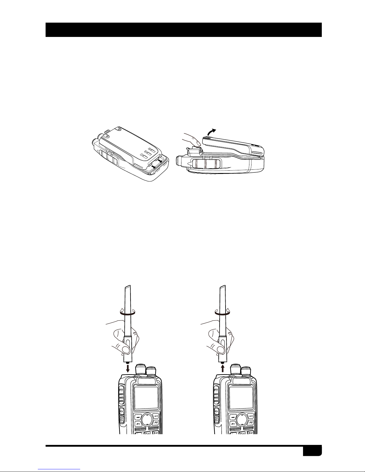
3.2
Installing / Removing the Antenna
a.
Installing the Antenna: Screw the antenna into the connector on the
top of the transceiver by holding the antenna at its base and turning it
clockwise until secure.
b.
Removing the Antenna: Turn the antenna counter-clockwise to remove
it.
3.1
Installing / Removing the Battery
a.
Match the two bottom grooves of the battery pack with the corresponding
guides on the back of the radio and then push it.
b.
To remove the battery pack, slide the release latch at the top away from
the battery and remove the pack away from the transceiver.
3. PREPARATION

8
AT-D868UV Digital DMR and Analog UHF/VHF Two Way Radio
3.4
Installing the Additional Speaker/Microphone (Optional)
Pry open the rubber MIC-Headset jack cover and then insert the Speaker /
Microphone plug into the double jack.
3.3
Installing / Removing the Belt Clip
a.
Installing the Belt Clip: Place the belt clip above the corresponding holes
on the back of the radio, and screw it into place clockwise with the two
supplied screws.
b.
Removing the Belt Clip:Unscrew counter-clockwise to remove the belt
clip.
3. PREPARATION

9
AT-D868UV Digital DMR and Analog UHF/VHF Two Way Radio
1
Antenna
2
Channel Switch
3
POWER/VOLUME Switch
Turn clockwise to switch on the radio
Turn counterclockwise till a click is heard to switch off the radio.
Rotate to adjust the volume after turning on the radio.
4
MIC Input
Please keep your mouth about 10cm away from the microphone to
achieve the best voice quality.
5
Speaker
6
LCD
Display the frequency/channel information, operation and status.
4. RADIO OVERVIEW
6
7
9
PTT
12
11
1
4
2
3
14
6
8
5
10
7
9

10
AT-D868UV Digital DMR and Analog UHF/VHF Two Way Radio
4. RADIO OVERVIEW
The top LED will help you to identify the current radio status.
4.1
LED Indications
LED Indication Status
Flashes Red Low battery voltage
Constant Red Transmitting
Constant Green Analog Receiving
Constant Cyan Digital Receiving
Flashes Green Scan
7
Menu key
Press to enter function menu set up;
Program the hot keys in PC software, press menu key, then press the
hot key to perform the programmed function.
8
Exit Key
In standby, press the key to enter the Contact list.
In menu, press the key to return the last menu.
9
P1 key/ P2 key
Programmable in PC software for different functions
10
Emergency Alarm Key
Programmable in PC software for other functions.
11
PTT (Push-To-Talk) Button
To make a call, press and hold the PTT button, then speak into the
microphone. Release the button to receive the signals.
12
[PF1]/[PF2] Key
Programmable in PC software for different functions.
13
Speaker/Microphone Jacks. PC program connector
14
Status Indicator
Indicate the different working status.

11
AT-D868UV Digital DMR and Analog UHF/VHF Two Way Radio
4.2
Programmed Key
In PC software – Public - Optional Setting - Key function, it is possible to
set different functions for [PF1], [PF2], [PF3],
, keys.
OFF No Function
Voltage Check the current battery capacity voltage
Power
Switch the power between super high, high, middle and low
power.
Repeater Switch between talk around and repeater mode
Reverse Turn on/off the frequency reverse function.
Digital
Encryption
Choose the encryption group
Call
In Analog mode, send the DTMF/5TONE/2TONE encode. This
function is only valid for analog channel.
TBST
In Analog mode, send the tone pulse frequency signal to active
the repeater.
VOX Set up the VOX level
VFO/MR Switch between VFO mode and memory channel mode.
Sub PTT Sub channel PTT, press to start the call on sub channel
Scan Scan on/off
FM Radio FM radio on/off
Alarm
Long press the key to start alarm, short press again to exit the
alarm.
Record switch Enable/disable the recording function
Record
Start/stop recording. When stop recording, the radio will remind
repeat or send the record.
SMS In digital mode, press to enter into messages
Dial Start the manually dial
GPS Check the GPS position information
Monitor Monitor the weak signal or the signal with unmatched ID.
Main channel
switch
Choose channel A or channel B as the main channel
Hot key 1~6
Press the key to perform the programmed function in hot key
setup
Alone Turn on/off the work alone function.
4. RADIO OVERVIEW

12
AT-D868UV Digital DMR and Analog UHF/VHF Two Way Radio
4.3
Default function
4.4
Hot Key
In PC software – Public – Hot key, it is able to set different functions for
hot key
~ and + number key. For details please refer to the PC
software.
+ number key operation:
Press
key until the LCD display “Next Please Press Dial Key”,
press the number key, it will perform the programmed function.
[PF1] (The radio key below PTT) – battery Voltage
[PF2] (The radio key 2 below PTT) – Monitor
[PF3] (Orange Alarm key) –Alarm
[P1] key – Main channel Switch
[P2]key – VFO/MR Switch
Call
Analog
Should edit the analog quick call rst, then choose analog
in the hot key set. Press the key to transmit 2Tone/5Tone/
DTMF to start the analog quick call.
Digital
It allows to select a contact from the digital contact
list, press the key to switch the channel to the contact
temporary. It will switch back to the original contact after
the group/personal call hold time.
Menu
SMS Quick access to Messages in the menu
New Msg Quick access to New Msg in the Menu - Messages
Quick Text Quick access to Quick Text in the Menu - Messages
Inbox Quick access to Inbox in the Menu - Messages
Outbox Quick access to Out box in the Menu - Messages
Contact list Quick access to Contact list in the Menu - Contacts
Manual dial Quick access to Manual Dial in the Menu - Contacts
Call Log Quick access to Call Log in the Menu
Sent Calls Quick access to Dialed Calls in the Menu - Call Log
Answered
Calls
Quick access to Answered Calls in the Menu - Call Log
Missed Calls Quick access to Missed Calls in the Menu - Call Log
Zone Quick access to Zone in the Menu
Radio set Quick access to Radio Set in the Menu - Settings
4. RADIO OVERVIEW

13
AT-D868UV Digital DMR and Analog UHF/VHF Two Way Radio
5.1
Power on the radio
5.2
Adjust Volume
5.3
Battery Voltage Test
5.4
Main band/Sub band switch
5.5
VFO/Channel switch
5.6
Set up VFO frequency
Turn on the radio by turning the [Power/Volume] switch clockwise till a click
is heard, and the LCD displays will show a start-up message, and you will
hear a beep after 7seconds.
Rotate the [Power/Volume] knob to adjust the volume. Turn clockwise to
increase the volume and counterclockwise to decrease the volume. The
LCD display will show the volume status during an adjustment.
Press the [PF1] key to check the current battery voltage, then press the
key again to return.
Press the key to switch the main channel to the other channel
if there is 2 channels shown on the display. The channel with bold
characters is the main channel.
Press the
key to switch between VFO and channel display.
»If the Channel is set to display a Channel name, this function is
invalid.
Turn the radio to VFO mode, press the key to switch the channel to
main band, the VFO frequency can only be set up when the channel is the
main “bold text” channel.
Operation 1:
Input the VFO frequency directly by the keyboard.
Operation 2:
Turn the channel selector to adjust the VFO frequency
steps.
5. BASIC OPERATIONS

14
AT-D868UV Digital DMR and Analog UHF/VHF Two Way Radio
5.7
Select a Zone
5.8
Select a Channel
A Zone is a group of channels grouped together. The D868UV DMR radio
has 250 Zones. A Zone can have the maximum of 160 analog and/or digital
channels.
Operation 1:
Press / directly to switch the zone, the LCD will
display the selected zone number or name.
Operation 2:
(1)
Press the Menu, press / to select Zone.
(2)
Press Select to enter Zone, press / to a Zone.
(3)
Press Select to enter a Zone.
Edit Name: Input the name, press conrm, and it will exit the Edit name
and ask to Save the name, press select to save the name, and it will
display“Saved”.
Select Zone: Press
/ to “Select Zone”, press select, the LCD will
display the selected zone number or name.
Operation 1:
Turn the channel switch to select a channel.
Operation 2:
Press key to switch the radio to Channel mode, input
the channel numbers by the keyboard. For example, if you want switch to
channel 99, input 0+0+9+9 a total of 4 digits, and it will switch to channel
99.
A channel can either be Analog or Digital.
For the analog channels the Push-To-Talk button is always available, and
on the Digital Channels parameters can be set up by the users / system
operators by channel to allow talk permit. There are four possible settings:
(1)
Always Allow: The user can transmit all the time.
(2)
Channel Free: The radio can transmit only if the channel is free.
(3)
Different Color Code: The radio can transmit if the channel is free, but
the color code is mismatch.
(4)
Same Color Code: The radio can transmit only if the channel is free and
the color code matches.
5. BASIC OPERATIONS

15
AT-D868UV Digital DMR and Analog UHF/VHF Two Way Radio
Making a Call
You can choose a target radio via 3 methods.
Method 1: from the Channel switch.
Turn the channel switch to choose a programmed channel.
Method 2: from the Contact list.
(1)
Turn the channel switch to choose a programmed channel;
(2)
Press (exit) key to enter the Contact List, press the / key to
choose a contact.
Method 3: from the keypad.
(1)
Turn the channel switch to choose a programmed channel.
(2)
Press (Menu) key to Contacts, press select to enter Contacts.
(3)
Press / key to Manual Dial, press Select.
(4)
Input the ID number by keypad, press key to switch group ID or
Private DMR ID.
Hold the radio vertical 2.5-5cm from your mouth, press the [PTT] key to
start the call, the red LED lights up, the receiver ID/name/city/state/country/
call type and call out icon will be display on the LCD.
Release [PTT] key to receive the reply.
5.9
Receiving and Responding to a Radio Call
When the radio is in the digital mode, it can receive and respond to a call
with the same frequency/color code/ slot.
When receiving a call:
a.
If the radio is programed with callers DMR ID number in the digital
contact list, when receiving a call, the radio will ring or vibrate briey.
b.
The blue LED lights up.
c.
The left top corner of LCD shows the RSSI icon, and the LED display will
show DMR ID/name/city/state/country/call type and incoming icon based
on what is in the contact list.
d.
When the call is ended, it will display “Call end”, and you can press [PTT]
to respond the call.
5. BASIC OPERATIONS

16
AT-D868UV Digital DMR and Analog UHF/VHF Two Way Radio
»In the PC software, Public - Optional Setting - Other - Mon Key
Function should be set up to Squelch Off.
5.10
Temporary Monitor
5.11
Monitor
In standby, press and hold the [PF2] key to enter Temporary Monitor. When
receiving matched carrier but the signaling / ID is unmatched or the signal
is too weak, this function allows monitor the weak signal and signal with
unmatched ID.
Release the [PF2] key to shut off speaker and return to standby.
In standby, press the [PF2] key to enter Monitor. When receiving matched
carrier but the signaling / ID is unmatched or the signal is too weak, this
function allows monitor the weak signal and signal with unmatched ID.
Press the [PF2] key again to shut off speaker and return to standby.
»In the PC software, Public - Optional Setting - Other - Mon Key
Function should be set up to Squelch Off Momentary.
5. BASIC OPERATIONS

17
AT-D868UV Digital DMR and Analog UHF/VHF Two Way Radio
6.1
Advanced Features for Private Call
6.2
Advanced Features
Method 1: Access from Contact list
a.
Press the (Exit) key to enter the Contact list, press the / key
to a private call ID name.
b.
Press Select to View Contact, press Select to see the contact
information.
c.
Press Option to access the advanced features.
(1)
Call Alert
Select Call Alert, it will send out a call alert, the target radio will sound a
beep or vibrate when receiving the call alert, and it will return a success
call or failed call message to the transmit radio.
(2)
Remote Monitor
Select Remote Monitor, and it will send out a signal for the target radio will
turn on its microphone and transmit when receiving the signaling, it will
send back the voice to the transmit radio. With this feature you can monitor
the sound activity near the target radio remotely.
(3)
Get GPS info
Select Get GPS info, and it will send out a signal to the target radio which
will start the GPS positioning and send a message of its GPS position to
the transmit radio.
(4)
Check Radio
Select Check Radio, and it will send out a radio check to the target radio
which will send back a message if it is available or not available to the
transmit radio. With this feature, you can determine if another radio is
active and powered on in the system.
Method 2: Access from Manual Dial
a.
Press the (Menu) key to enter Contacts, press / key to
Manual Dial.
b.
Press Select to enter Manual Dial.
c.
Input the Private ID, press Option to access the advanced features.
6. ADVANCED FEATURES

18
AT-D868UV Digital DMR and Analog UHF/VHF Two Way Radio
(5)
Kill
Select Kill, and it will send out a kill signaling to the target radio which will
be killed (No display, no operation) when receiving the signaling and it will
send back a kill successful message to the transmit radio.
(6)
Wake
Select Wake, and it will send out a wake signaling to the killed radioand the
target radio will return to standby when it receives this signaling and send
back a Wake successful message to the transmit radio.
6. ADVANCED FEATURES

19
AT-D868UV Digital DMR and Analog UHF/VHF Two Way Radio
7.1
Turn on GPS
7.2
Check the GPS Information
7.3
Send GPS Information
a.
Press (Menu) to enter the main Menu, press / key to
Settings.
b.
Select Radio Set, press the / key to GPS Set
c.
Select GPS Set, press / key to GPS On
d.
Select GPS On.
Method 1: Check GPS info from Menu
Press
(Menu) key to enter Main Menu, press / key to GPS
info, press select to check the GPS info.
Method 2: Check GPS info from programmed key
In the PC software, Public – Optional Setting – Key function, program a key
as GPS, press the programmed key to check the GPS info.
a.
When the GPS is positioning successfully, the GPS icon shows a red
color. Follow the above step to check the GPS info, press edit key to
Text edit.
b.
Press Conrm, and it will display Send or Save. If you select Save, the
GPS info will be saved as a draft message.
c.
Choose Send and it will display Contact list or Manual Dial.
d.
Select Contact list to choose a contact, press select to send the GPS
info. or
e.
Select Manual Dial, input the DMR ID, press key to switch group ID
or private ID, press select to send the GPS info.
»If the GPS is not positioning, it will display “No Fixed Position”,
and the GPS icon shows a grey color. Move the radio to an open
window or outdoors, and it will take a few minutes to connect to
the GPS Satellites.
7. GPS POSITIONING FUNCTION

20
AT-D868UV Digital DMR and Analog UHF/VHF Two Way Radio
»When GPS is on and positioning successfully, it will auto send out
the GPS information when the radio starts the alarm.
7.4
Man Down Alarm
a.
Press (Menu) to enter main Menu, press / key to Settings.
b.
Select Radio Set, press / key to 25 Man Down.
c.
Select Man Down On to turn on the function.
When the function is on, the radio will start alarm if the radio is falling to the
ground. Raise the radio to stop the alarm.
7. GPS POSITIONING FUNCTION

21
AT-D868UV Digital DMR and Analog UHF/VHF Two Way Radio
8.1
Turn on/ off the Recording
8.2
Play the Record
8.3
Send the Record
8.4
Recording Manually
a.
Press (Menu) enter main Menu, press / key to Record.
b.
Select Record Switch, select on or off to turn on or off the Record.
When the function is on, the radio will record the talking during the
communication.
a.
Press (Menu) to enter main Menu, press / key to Record.
b.
Select Record List to enter Record list, select a Record list to enter the
Record le.
c.
Select a Record to see the detail information.
d.
Select Record Play to play the record.
a.
Press (Menu) to enter main Menu, press / key to Record.
b.
Select Record List to enter Record list, select a Record list to enter the
Record le.
c.
Select a Record to see the detail information.
d.
Select Record Send, and it will display the Contact list or Manual Dial.
e.
Select Contact list to choose a contact, press select to send the Record.
f.
Select Manual Dial, input the DMR ID, press key to switch group ID
or private ID, press select to send the Record.
In the PC software, Public – Optional Setting – Key function, program a key
as Record.
a.
Press the programmed Record key, and the radio will start the recording,
and speak into the microphone.
b.
Press the programmed Record key again to stop the recording, and the
radio will display Record Play or Record Send.
c.
Select Record Play, and the radio will play the record.
d.
Select Record Send, and the radio will display Contact list or Manual
Dial.
8. RECORDING

22
AT-D868UV Digital DMR and Analog UHF/VHF Two Way Radio
8. RECORDING
e.
Select Contact list to choose a contact, and press select to send the
Record.
f.
Select Manual Dial, input the DMR ID, press key to switch group ID
or private ID, press select to send the Record.
»The Recording function is only valid in digital channel.

23
AT-D868UV Digital DMR and Analog UHF/VHF Two Way Radio
9.2
Messages
9.3
Call Log
9.4
Scan List
New Msg:
Create a new message and send to a contact.
InBox:
Shows all the received messages, and allows forward or delete the
message.
OutBox:
Shows all the sent messages, and allows resend, forward or
delete of the message.
Quick Text:
Pre-saved messages, and allows to send, edit or delete the
message.
Draft:
Draft messages, and allows send, edit or deleting of the message.
Sent:
Shows all the dialed calls, and allow deleting the call record or
saving the ID as a new contact.
Answered:
Shows all the answered calls, and allows deleting the call
record or saving the ID as a new contact.
Missed:
Shows all the missed calls, and allows deleting the call record or
saving the ID as a new contact.
In the PC software – Public – Scan list, it allows to save 250 scan lists, and
to program the required scan lists and write it into radio.
Switch the radio to channel mode, as the scan list is only valid in the
channel mode.
Select a Scan list as current scan list, then you can also reset the priority
channel 1 and priority channel 2 in the scan list.
9.1
Contacts
Contacts List:
Will display the digital contact list which had been
programmed in the PC software. This list is used as a look-up table to
display the contact person information when receiving a call.
New Contact:
Allows to create a new digital contact.
Manual Dial:
Input the group ID or private ID to access a contact quickly.
9. MAIN MENU

24
AT-D868UV Digital DMR and Analog UHF/VHF Two Way Radio
9.5
Settings
9.5.1
Radio Set
(1)
Beep
Beep On: The radio will beep when you press the keypad
Beep Off: No beep when you press the keypad.
(2)
Back Light
LCD backlight intensity is adjustable in 5 steps
(3)
Ch. Name
CH name: The radio will work in channel mode and display the channel
name, and then the programmed VFO/ MR key is not valid.
Frequency: The radio will work in VFO mode and display the frequency,
which allows the programmed VFO/MR key to switch the VFO and Memory
channels.
(4)
Key Lock
Manual Lock: Long press the
key to lock the keypad. Press Func key,
then press the key to unlock the keypad.
Auto Lock: Radio will auto lock the keypad when standby for a while. Press
[Func] key, then press the key to unlock the keypad
(5)
Power Off
Allow to set automatic power off when not used for a period of 10 minutes,
30minutes, 1 hour or 2 hours of inoperation.
Off: Turn off the function.
(6)
TX Timer
30S-240S: The TX will be limited in the set time. When this time is reached,
the radio will auto stop transmission.
OFF: Turn off the TX time limit, and there is no limit for the transmission time.
(7)
Language
Choose the Chinese or English.
(8)
Menu Exit Time
5S-20S: When enter the menu, the radio will stay at the menu in the set
time. When the time is reached, the radio will auto exit the menu.
(9)
Intro Display
Picture: The radio will display an AnyTone picture when powered on.
Character: The radio will display the characters set up in PC software when
powered on.
9. MAIN MENU

25
AT-D868UV Digital DMR and Analog UHF/VHF Two Way Radio
(10)
Main Ch
Channel A: The upper displayed channel will be set to be the main channel.
Channel B: The lower displayed channel will be set to become the main
channel.
(11)
Sub Ch
Sub Channel On: Turns on the sub channel, and the radio will display both
channel.
Sub Channel Off: Turns off the sub channel, and the radio will display the
main channel only
(12)
Msg Note
Different prompt options when receive a new message.
(13)
Call Ring
Different prompt options when receive a new call.
(14)
Freq Step
2.5K,5K,6.25K,10K,12.5K,20K,25K,30K,50K, a total of 9 frequency steps
offered.
(15)
SQ level
Adjusts the squelch level to receive signal with different signal strength,
and a total of 5 levels offered. This function is only valid for analog channel.
(16)
Power Save
Turn on the function to extend the battery life.
(17)
TBST Sel
TBST frequency is used to activate some dormant repeaters, 1000Hz,
1450Hz,1750Hz, 2100Hz a total of 4 options are offered.
(18)
VOX
Enable the VOX, you can speak into the microphone to start transmitting
instead of pressing the [PTT] key. A total of 3 levels are provided.
(19)
VOX Delay
When the VOX is enabled, set up the VOX delay to help to extend the
transmission time to avoid stopping a transmission too early. 0.5s-3s, a
total of 26 times offered.
(20)
Scan Mod
SCM TO: When scanning and stopping for a signal, stays at the channel
5s before resuming the scan.
9. MAIN MENU

26
AT-D868UV Digital DMR and Analog UHF/VHF Two Way Radio
SCM CO: When scanning and stopping for signal, stays at the channel
until the signal disappears, and resumes scan 2s later.
SCM SE: When scanning and stopping for a signal, will terminate the scan.
This function is only valid for a VFO scan.
(21)
Mic Level
Allows to adjust the Microphone gain, level 1 is the lowest, level and 5 is
highest gain.
(22)
DTMF Speed
Offers DTMF encode speed which will help the receiver decode
successfully, 50~500ms are the options.
(23)
FM Radio
Turn on or off the FM radio.
(24)
FM Radio Moni
Radio Mon On: When FM radio is used, you can still receive or transmit on
the channel.
Radio Mon Off: When FM radio is used, the radio will not permit a
transmission or reception.
(26)
Start Up Pwd
On: Set up the password for start up. You need to input the password to
power on the radio.
Off: No password is required for the radio power on start up.
(27-31)
Key PF1, PF2, PF3, P1, P2
You can program these keys for different functions.
(33)
Time Zone
Set up the time zone of your location.
(34)
Date Time
Time Check: Allows to set up the date and time manually. Use the
/
key to set the current year. Move to the month by pushing the
key. Set the month, and use the
key to move forward each step. Once
done, click the Menu key to save the date and time.
GPS Check: When GPS is positioning successfully, enter this menu, select
GPS check to do the date & time correction automatically.
9. MAIN MENU

27
AT-D868UV Digital DMR and Analog UHF/VHF Two Way Radio
9.5.2
Chan Set
※
Chan Set (Digital Channel)
(1)
Channel Type
A-Analog : Set up to analog channel
D- Digital : Set up to digital channel
A+D TX A: Mixed analog, allow receive analog and digital signal, TX is
analog.
D+A TX D: Mixed digital, allow receive analog and digital signal, TX is
digital.
(2)
TX Power
Set up the TX power for current channel.
(3)
Band Width
Only narrow band 12.5KHz for digital channel.
(4)
RX Freq
Input the RX frequency by keypad, click the Menu key to save, press P2
key to return.
(5)
TX Freq
Input the TX frequency by keypad, click the Menu key to save, press P2
key to return.
(6)
Talk Around
When the TX radio and RX radio both are set up with Talk Around on, they
can communicate directly without a repeater. The analog channel will use
the RX frequency as TX/RX frequency, the RX CTCSS/DCS decode as TX
CTCSS/DCS encode.
(7)
Name
Allow reset the channel name, this function is only valid in channel mode.
(8)
TX Permit
Always: Always allow transmit
Channel Free: Allow transmit when the channel is free
Different CC: Allow transmit when receive matched signal but different color
code.
The channel set menu will change accordingly to the channel type. When
the channel type is digital, it will auto hide the analog menus
.
9. MAIN MENU

28
AT-D868UV Digital DMR and Analog UHF/VHF Two Way Radio
Same CC: Allow transmit when receive matched signal and same color
code.
(9)
TX Prohibit
TX ON: Will allow transmit on the current channel.
TX OFF: Will not allow transmit on the current channel.
(10)
Radio ID
In Digital channel, it will show the DMR ID which must be programmed in
the PC software – Digital – DMR ID list- DMR ID. Allows edit and select an
ID for the channel, each channel allows one ID.
In Analog channel, it will show the radio self ID which is programmed in PC
software – Analog –Analog Address Book – Number.
(11)
Colour Code
The digital channel should have the same color code for communication as
dened by the repeater to be used; which can be programmed in the PC
software or dened in the Menu.
(12)
Slot Set
Set up Slot 1 or Slot 2 for the current channel.
(13)
Digi Encrypt
With the digital encryption, the communication will be condential. A total
of 32 digital encryptions is offered, and it can be programmed in the PC
software or dened in the Menu.
(14)
Encrypt Type
Choose normal encryption or enhanced encryption type.
(15)
Work Alone
In the PC software – Public – Alarm settings – Work Alone, you have to set
up the response time, warn time and response method initially.
Turn on the work alone function for the current channel. When the radios
predetermined time has been reached for the alone working time, the radio
will beep a sound and show “Work Alone Predict”. The user has to conrm
by pushing the programmed work alone key to confirm continuing work
alone, otherwise, the radio will start its alarm and send the alarm on the
channel when reaching its preset response time.
9. MAIN MENU

29
AT-D868UV Digital DMR and Analog UHF/VHF Two Way Radio
※
Chan Set (Analog Channel)
When the channel type is analog, it will auto hide the digital menus,
instead, the channel set will show the analog menus.
The below listed menus are for analog channel only, other not listed menus
are same as the digital channel.
(2)
TCDT
Set up the CTCSS/DCS code for the TX.
(3)
RCDT
Set up the CTCSS/DCS code for the RX.
(4)
RTCDT
Set up the CTCSS/DCS code for both TX and RX
CTCSS code: 62.5Hz~254.1Hz, a total of 51 groups
DCS code: 000N~7771, a total of 1024 groups.
(5)
Optional Signal
Allows the set up of DTMF/5TONE/2TONE encode and decode for the
analog channels.
(7)
Squelch mode
When the analog channel is set up for both CTCSS/DCS decoding and
optional signaling, you can set up the RX condition in this menu.
SQ: You can hear the call once the channel receive matched carrier.
CDT: You can hear the call when the channel receive matched CTCSS/
DCS signal
TONE: You can hear the call when the channel receives a matched
signaling.
C&T: You can hear the call when the channel receives a matched CTCSS/
DCS and matched signaling.
C|T: You can hear the call when the channel receives a matched CTCSS/
DCS or matched signaling.
(8)
Band Width
Choose wide band or narrow band for the analog channel.
(9)
Reverse
When this function is enabled, the RX frequency, TX frequency and
CTCSS/DCS encode/decode will be reversed.
9. MAIN MENU

30
AT-D868UV Digital DMR and Analog UHF/VHF Two Way Radio
9.5.3
Device Info
Show the Radio ID, Radio name, serial number, model name, frequency
range, rmware version, radio data version, latest program date, picture
version, language version etc.
(14)
Busy Lock
Always: Always allows transmissions
RL: Will not allow transmit when receiving matched carrier but unmatched
CTCSS/DCS.
BU: Will not allow transmit when receiving matched carrier.
(15)
OWN ID
When the analog channel set up with optional signal, you can check the
radio ID number in this menu. The ID number should be set up in PC
software – Analog – Analog Address Book.
(17)
DTMF Enc
Set a DTMF ID as the default call ID for the current channel.
Press the PTT key to transmit the selected DTMF ID.
Edit the DTMF ID in Menu or with the PC programing software.
(18)
2Tone Enc
Set a 2Tone as the default call ID for the current channel.
Press the PTT key to transmit the selected 2Tone.
Edit the 2Tone in the PC programing software before it can be selected.
(19)
5Tone Enc
Set a 5Tone as the default call ID for the current channel.
Press the PTT key to transmit the selected 5Tone.
Edit the 5Tone in the PC programing software before it can be selected.
9. MAIN MENU

31
AT-D868UV Digital DMR and Analog UHF/VHF Two Way Radio
Problems Solutions
The radio cannot be switched
on or no display after being
switched on.
A. Battery pack may not be installed
properly. Remove the battery pack
and install it again.
B. Battery power may be insufcient.
Recharge or replace the battery
pack.
The battery doesn't last very
long after charging.
The battery is defective; please replace it
with a new battery pack.
Cannot talk to or hear other
members in your group.
Other voices from
non-group members are heard
on the channel.
Analog: Change the CTCSS/DCS
tone, and make sure to change the tone
on all radios in your group.
1. Make sure the frequency and
CTCSS are the same as other
members.
2. Make sure you are within range,
and not too far away from your
member.
3. Make sure you are set in correct
digital mode, and frequency.
4. In digital mode, make sure set
correct code and encrypt group is
used in current channel.
5. n digital mode, make sure set
correct receiving contacts and
receiving group is used.
10. TROUBLE SHOOTING GUIDE

32
AT-D868UV Digital DMR and Analog UHF/VHF Two Way Radio
11. PROGRAMMING GUIDE
Multiple Radio ID’s
Amateur DMR-MARC
Anytone AT-D868UV radios ship from the manufacturer “Keypad” locked
per FCC rules.
You can press the
(Menu) key and the (star) key to unlock the
keypad for the rst time of use. You will need the programming cable to
connect your radio to your computer for programming
.
The programming software and codeplug programming guide are available
for download from Anytone website: http://www.anytone.net/about/about8.
html
When programming this radio for the first time, it is recommended you
first READ the radio with the software and then save this file for future
reference as it contains the default programming and settings. In addition,
after you READ this radio with software, rst make your programming and
frequency changes, then send this edited le back to your radio.
The AT-D868UV radio will allow multiple DMR Radio ID numbers to be
used with the radio. This feature will allow one radio to be used for example
as a Commercial Radio with its own DMR ID, and at the same time also be
used as an Amateur radio with another DMR ID.
In PC software, Digital/ Radio ID List, you can enter your Department Unit
Number or Amateur Radio callsign.
For the best Amateur DMR experience obtain a subscriber ID from one of
many available
Amateur sources. A U.S. Amateur user can obtain an ID from:
http://www.dmr-marc.net/cgi-bin/trbo-database/register.cgi
then scroll down to the user registration button.
Another place to register: http://register.ham-digital.net/
For DMR repeaters in your area please see:
https://www.google.com/maps/d/u/0/viewer?mid=zDtc036qqpwA.kMwk4xZNenc&msa=0

33
AT-D868UV Digital DMR and Analog UHF/VHF Two Way Radio
World DMR repeater network map:
http://www.dmr-marc.net/repeaters.html
World DMR repeater network with veried Talkgroups by activity:
http://dmrx.net/dmrx-map.html
The AT-D868UV DMR radios contain a separate database memory for
importing and displaying Amateur DMR individual IDs, call sign and user
name in comma-delimited format (.csv)
Please reference in the programming guide for import and export database
operations detailed.
Worldwide Amateur Contact Database
11. PROGRAMMING GUIDE

34
AT-D868UV Digital DMR and Analog UHF/VHF Two Way Radio
The Anytone website provides additional information about obtaining
service or support for the Anytone line of two-way radios and accessories.
Visit: www.anytone.net
Warning Notes
Every effort has been made to ensure that the information in this document
is complete, accurate, and up to-date. Anytone Radio assumes no
responsibility for the results of errors beyond its control. The manufacturer
of this equipment also cannot guarantee that changes in the equipment
made by non-authorized users will not affect the information in it.
FCC Licensing Information
This Anytone radio operates on Commercial / Land Mobile frequencies
which require a license from the Federal Communications Commission
(FCC) for business, personal, education and recreational use. To obtain
forms, call the FCC forms hotline at: 1-800-418-3676 or go to http://www.
fcc.gov
For questions concerning commercial licensing, contact the FCC at
1-888-CALL-FCC(1-888-225-5322).
12. ON-LINE SERVICE AND SUPPORT

35
AT-D868UV Digital DMR and Analog UHF/VHF Two Way Radio
The Anytone AT-D868UV DMR handheld transceiver has been carefully
designed to provide you with years of safe, reliable operation. As with
all electrical equipment, however, there are a few basic precautions you
should take to avoid hurting yourself or damaging the radio:
• Read the instructions in this handbook carefully. Be sure to save it for
future reference.
• Read and follow all warning and instruction labels on the radio and
owner’s manual.
• Do not carry the transceiver by the antenna. This may damage the
antenna or antenna terminal. Grasp the handheld by its base (not the
antenna) when you need to place or remove it.
• Do not keep the radio with the antenna very close to, or touching exposed
parts of the body, while transmitting. Anytone radios will perform best, if
you speak 2-4 inches away from the microphone and the radio is vertical.
• Be sure the “PTT” key is not pressed when you do not need to transmit.
• Do not operate the radio near unshielded electrical blasting caps or in an
explosive atmosphere.
• Do not transmit without the antenna fitted on the radio. Though it is
provided with a protection, it may damage the TX output nal stage.
• Respect the environment conditions. The radio is designed to be used in
heavy environments, however avoid exposing it to extremely hot or cold
temperature (out of the range between –20 to +140°F). Do not expose the
transceiver to excessive vibrations as well as dusty or rainy locations.
• Never try to disassemble or service the radio by yourself (aside from the
routine maintenance described in this handbook). It may cause damage
to the radio transceiver and void your warranty requiring extensive repair
work. Always contact your local dealer for assistance.
• Use only authorized accessories. Using non Anytone radio brand
accessories may seriously damage your handheld transceiver and void
your warranty.
• Do not spill liquid of any kind into your radio. If the transceiver gets wet,
immediately dry it by a soft and clean cloth.
• Switch the radio off before you clean it. Follow the directions described in
the paragraph “Care and maintenance”.
SAFETY

36
AT-D868UV Digital DMR and Analog UHF/VHF Two Way Radio
• Handle the battery properly. Never place the LI-ion battery in your pocket
or purse with loose coins. This could result in short circuiting the battery.
• Be certain that your power source matches the rating listed for the
supplied battery charger (AC adapter). If you are not sure, check with your
authorized Anytone dealer.
• Avoid damaging the power cable of the battery charger. Do not step on
or place anything on it as this could result in a damaged charger power
cord. This product complies with the requirements of the Council Directives
89/336/EEC and 73/23/EEC on the approximation of the laws of the
member states relating to electromagnetic compatibility and low voltage.
Your wireless hand-held portable transceiver contains a low power
transmitter. When the Push-to-Talk (PTT) button is pressed it sends out
radio frequency (RF) signals. The device is authorized to operate at a duty
factor not to exceed 50% TX and 50% RX.
In August 1996, the Federal Communications Commission (FCC) adopted
RF exposure guidelines with safety levels for hand-held wireless devices.
To maintain compliance with the FCC’s RF exposure guidelines, this
transmitter and its antenna must maintain a separation distance of least 2
inches from your face. Speak in a normal voice, with the antenna pointed
up and away from the face at the required separation distance. The belt
clip is for storage purposes only.
AVOID TRANSMITING ON HIGH POWER WHILE RADIO IS ATTACHED
TO YOUR BELT. To transmit, hold the device away from your body and
ensure the antenna is at least 2 inches from your body when transmitting.
WARNING
SAFETY

37
AT-D868UV Digital DMR and Analog UHF/VHF Two Way Radio
General
Frequency Range 136-174MHz (V) , 400-480MHz (U)
Channel Capacity 4000 channels
Channel Spacing 25KHz (Wide Band) ,12.5KHz (Narrow Band)
Phase-locked Step 5KHz, 6.25KHz
Operating Voltage 7.4V DC ±20%
/(2100mAh)
Frequency Stability ±2.5ppm
Operating Temperature -20℃~ +55
℃
Size 129×61×39mm (with battery pack)
Weight 282g (with battery pack, antenna)
Receiving Part
Wide band Narrow band
Sensitivity(12dB SINAD) ≤0.25μV ≤0.35μV
Digital Sensitivity
0.3uV/-117.4dBm (BER 5%)
0.7uV/-110dBm (BER 1%)
Adjacent Channel Selectivity ≥70dB ≥60dB
Spurious Emission ≤-57dB ≤-57dB
Spurious Rejection ≥70dB ≥70dB
Blocking
84db
Hum & Noise ≥45dB
≥
40dB
Audio Distortion ≤5%
Audio Power Output 1000mW/16Ω
Transmitting Part
Wide band Narrow band
Power Output VHF: 7/5/2.5/1W, UHF: 6/5/2.5/1W
Modulation ±5.0KHz@25KHz ±2.5KHz@12.5KHz
Adjacent Channel Power ≥70dB ≥60dB
Hum & Noise ≥40dB ≥36dB
Spurious Emission ≤-36dB ≤-36dB
4FSK
Digital Modulation
12.5KHz(data)7K60FXD
12.5KHz(data+voice)7K60FXE
Audio Distortion ≤5%
Error rate
≤3%
13. TECHNICAL SPECIFICATIONS
 Loading...