

Page 1

I
Page 2

P/N: QSD 501 – ENG – Rev 3 – 2012
Page 3

Chapter 1
First Steps
1.1
Know the QS5
1
1.1.1
Front panel
1
1.1.2
Connectors
2 1.2
Install or replace batteries
2 1.3
Connecting the transducer
5 1.4
The “Q” key
6 1.5
Display illumination and contrast
6
1.5.1
Display backlight illumination
6
1.5.2
Display contrast
7 1.6
Locking and unlocking the keypad
7
Chapter 2
Measuring with the QS5
2.1
Numerical measure screen (Normal)
9
2.1.1
Screen mode-1 (Min., Max.)
9
2.1.2
Screen mode-2 (Percentage Value)
10
2.1.3
Screen mode-3 (Datalogger)
11
2.2
Keys in numerical measure modes
11 2.3
BScan graphic measure screen
14 2.4
Keys in BScan graphic measure sceen mode
15 2.5
Zero calibration (Auto)
15 2.6
1-Point and 2-Point calibration
17 2.7
Changing the material velocity
19
2.7.1
Change to a known velocity
19
2.7.2
Change velocity using a known
thickness value
19
2.8
Adjusting trigger and gain
20
2.9
Understanding the coupling icons and the
energy level indicator
21
2.9.1
Coupling icons
21
2.9.2
Coupling energy level indicator
22 2.10
Measuring thru-coating or thru-paint
25
I
Page 4

Chapter 3
Menu system and editing
3.1
Instructions on using the menu system
28
3.1.1
Text editor
29 3.2
Main menu
31
3.2.1
Change measuring unit
31
3.2.2
Alarm settings
31
3.2.3
Set BScan range
33
3.2.4
Select language
33
3.2.5
Unit information
34 3.3
General configuration options
34
3.3.1
Set time and date
35
3.3.2
Set time and date format
35
3.3.3
Set keypad sensitivity
36
3.3.4
Set auto-off time
37
3.3.5
Adjust display contrast
37
3.3.6
Beep activation
38
3.3.7
Introduction screen
38
3.3.8
Owner information
38
3.3.9
Lock configuration options
40
3.3.10
Model upgrade licenses
41
3.3.11
Return to factory default settings
42 3.4
Measuring configuration options (Ultrasonic)
43
3.4.1
Set material velocity
43
3.4.2
Select measure mode
44
3.4.3
Adjust gain
45
3.4.4
Adjust trigger
45
3.4.5
Select refresh rate
45
3.4.6
Select transducer frequency
46
3.4.7
Select coating type
46
3.4.8
Select calibration mode
47
3.4.9
Hold last value
48
3.4.10
Energy level compensation (DAC)
48
3.4.11
Material condition analyzer
49
II
Page 5

3.4.12
Nums Zoom measuring screen mode
50
3.4.13
Continuous measuring monitor
50
3.4.14
Adjust pulser excitation voltage
51
3.4.15
Return to factory default settings
52
Chapter 4
Using the Datalogger
4.1
Understanding how data is organized
53 4.2
Memory menu
53 4.3
Creating a file
54 4.4
Actions over single files
55
4.4.1
View data in a single file
56
4.4.2
The “Q” key in a grid
56
4.4.3
The “Q” key in a histogram
57
4.4.4
The “Q” key in a SCAN graphic
59
4.4.5
Send data from a single file
60
4.4.6
Rename a file
60
4.4.7
View file size
60 4.5
Actions over all files
60
4.5.1
Send all files
61
4.5.2
Erase all files
61 4.6
The Datalogger in the measuring screen
62
4.6.1
Datalogger information
62
4.6.2
Quick memory menu (Mem key)
63 4.7
Connecting to a PC with DataCenter
64
4.8
Datalogger configuration
65
4.8.1
Configure communications
65
4.8.2
Capture modes
66
4.8.3
Set number of values
67
4.8.4
Selecting fixed batch
67 4.9
Advanced Datalogger configuration
68
4.9.1
Store every (N) number of values
68
4.9.2
Record operator actions
68
4.9.3
Record date and time
69
III
Page 6

Tips on how to measure correctly
Technical specifications
Additional information
Unit maintenance
QS5 accessories
Error messages
Our website: www.demeq.com
Technical support
IV
Page 7

And thank you for purchasing a QS5 ultrasonic corrosion and wall
thickness gauge.
At dmq we develop, manufacture and distribute software and quality
control instruments offering innovation and solutions that come as a
direct result of listening to your needs as a user. We apply some of the
latest technology available in the industry to build instruments that are
robust, precise, and easy to operate.
We are convinced that our products would not be complete without
permanent technical and after sales support. So in addition to a great
product we offer:
Quick answers to your inquiries.
Unlimited access to technical information as well as
application notes.
Special offers for registered customers.
Firmware and software upgrades at no charge.
Attention to your inquiries and suggestions.
We hope that the QS5 will meet and exceed your application needs.
V
Page 8
The information included in this manual applies to all QS5 series
ultrasonic corrosion and wall thickness gauges including models B, DL,
E and DLE.
dmq is a registered trademark of demeq S.R.L and its affiliate
companies.
The information contained in this manual is intended to educate users
on the operation of the QS5 gauges. Failure to read and understand
this manual can lead to measurement errors. Decisions based on
measurements and or results that are erroneous can lead to property
damage, personal injury or even death. Demeq S.R.L assumes no
responsibility as a result of the improper use of our instruments.
ASTM E797
The user must be trained in ultrasonic testing procedures and on how
to properly configure the unit for testing. All of the following should
be taken into consideration:
Understand the theory on sound wave propagation.
Select the instrument as well as the transducer that is best
suited for your application.
Know the specific requirements for the test you will be
conducting.
This manual provides all of the information needed to configure and
operate the QS5 gauge. However there are additional factors that can
VI
Page 9
affect tests done with this instrument. Specific information on those
factors is outside the scope of this manual. When in doubt you should
always seek expert advice or refer to specific textbooks on ultrasonic
testing. Additional information can also be found on the internet and
through local government agencies as well as in technical institutes.
The QS5 operates with dual crystal transducers that use the “pitchcatch” principal. Dual crystal transducers use two piezoelectric crystals
whereby one crystal is excited with short electrical pulses from the unit
sending short acoustic waves into the test piece. The second crystal
then receives the acoustic waves reflected at the end of the test piece.
The frequency of the acoustic waves changes between 2 and 10 MHz
depending on the probe being used.
All QS5 gauges operate in Echo-1 or normal (no coat) mode where a
measurement is the result of the sum of the time delay from the
transducer and the time it takes for the acoustic wave to rebound back
to the transducer after it reaches the end of the test piece. In Echo-2 or
thru-paint mode (QS5 E and QS5 DLE only), the unit measures the time
interval between the first and second echoes and does not take into
consideration the time delay from the transducer.
VII
Page 10
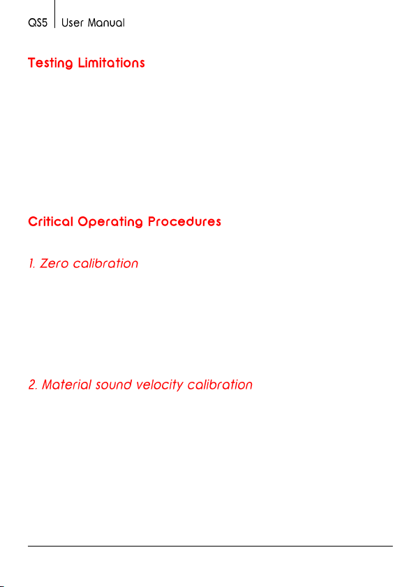
Figure 1: Echo-1 and Echo-2 mode acoustic wave representation
In ultrasonic testing information is obtained from measuring sound
waves. Users must be very careful when making assumptions in
regards to the entire test piece condition when there are areas that
have not been inspected. In large and massive test pieces it would be
practically impossible to test the entire piece and therefore conclusions
for the whole piece based solely on the areas that have actually been
inspected, should only be done by experienced operators. Only trained
users should evaluate test pieces that could present erosion and or
corrosion.
In order to minimize test result errors the following must be observed:
Before taking actual measurements the unit and transducer have to be
calibrated. Calibration of the transducer is also known as zero
calibration or delay calibration (Page 15). If the unit and transducer are
not calibrated, or calibrated incorrectly, the resulting measurements
will be unreliable. Each and every time a transducer is changed it must
be calibrated to the unit.
Because the sound velocities in materials will often vary significantly
from published values, best results are obtained when the instrument
is calibrated on a reference test block made from the same material as
that of the actual test piece. The block should be flat, of a smooth
finish, and be as thick as the maximum thickness of the test piece.
Careful consideration by the user must be made when evaluating the
accuracy of a thickness value because considerable changes in the
sound velocity of a material may have occurred as a result of a
treatment. So for example a test piece made of steel that has been
thermally treated, will look the same as a regular test piece made of
VIII
Page 11
untreated steel, but the sound velocities vary significantly. Instruments
should be calibrated before and after testing to minimize errors.
Transducers must be in good condition and show no visible signs of
excessive wear or defects on their surface. Badly worn transducers can
provide erroneous measurements.
The thickness of the material being tested must be within the specified
thickness range of the transducer and the temperature of the material
must also be within the specified temperature range of the transducer.
Calibration as well as actual testing should be performed under similar
coupling conditions. Couplant must be applied in an even and
consistent manner to minimize variations in couplant layers that may
result in testing errors. The amount of couplant should be kept to a
minimum and consistent pressure should be applied on the transducer
when measuring.
Doubling refers to a thickness measurement that displays a reading
that is twice or even three times the real test piece thickness. Doubling
often may happen when trying to measure below and above the
specified range for the transducer and when using worn transducers.
When in doubt, the test piece thickness must be measured using other
methods and or instruments and the unit must then be calibrated
using reference test blocks of known thickness values that are made of
the same material as the actual test piece. This is very important when
measuring unknown test pieces for the first time.
When possible calibrate your instrument on-site using a test block that
is at the same temperature as the test piece in order to minimize
errors.
IX
Page 12

All QS5 series corrosion and thickness gauges are for industrial use
only and cannot be used in medical applications. The QS5 operates on
two AA size batteries. We strongly recommend that you use only top
brand name alkaline batteries.
Disposal of your QS5 gauge and its components must be done in
compliance with all applicable regulations.
Because of its complexity level, software is never really completely error
free. For this reason in software controlled instruments always make
sure that the operations required for your application are in correct
working order.
Demeq S.R.L provides a limited warranty for a period of 2 (two) years
on electronic units and for 6 (six) months on transducers from the date
of purchase and may be extended for up to 5 years.
Every instrument undergoes thorough testing during manufacturing as
well as before shipping. In the event warranty service where to become
necessary, dmq and or your local distributor or representative will
make a reasonable effort to replace your defective unit with another
new or used unit, while your instrument undergoes warranty repair.
X
Page 13
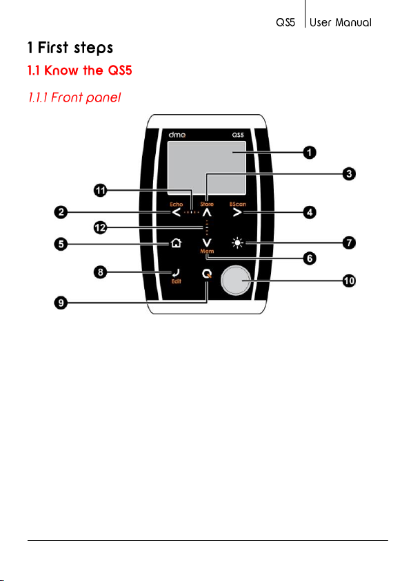
Figure 1.1: Front of the unit
1. Graphic LCD display with LED backlight illumination
2. Move Left key / Switch measuring modes: normal
measurements or Echo-1 / Thru-Paint or Echo-2 (Echo)
3. Move Up key / Manually store a value (Store)
4. Move Right key / Switch to graphical measure mode screen
(BScan)
5. Menu key / Enter and exit measure screen / Exit and return to
menus (Home)
Chapter 1 1
Page 14
6. Move Down key / Quick access to memory menu screen
options (Mem)
7. Change backlight illumination key (On, Off, Auto)
8. Enter key / Edit values on the measure screen (Edit)
9. The key: Power On and Shutdown (touch and hold for 2
seconds) / Make quick and short touches to activate special
functions and features
10. Calibration disk
11. Horizontal scrolling center point (lock and unlock keypad on
measure screen)
12. Vertical scrolling center point (adjust LCD contrast)
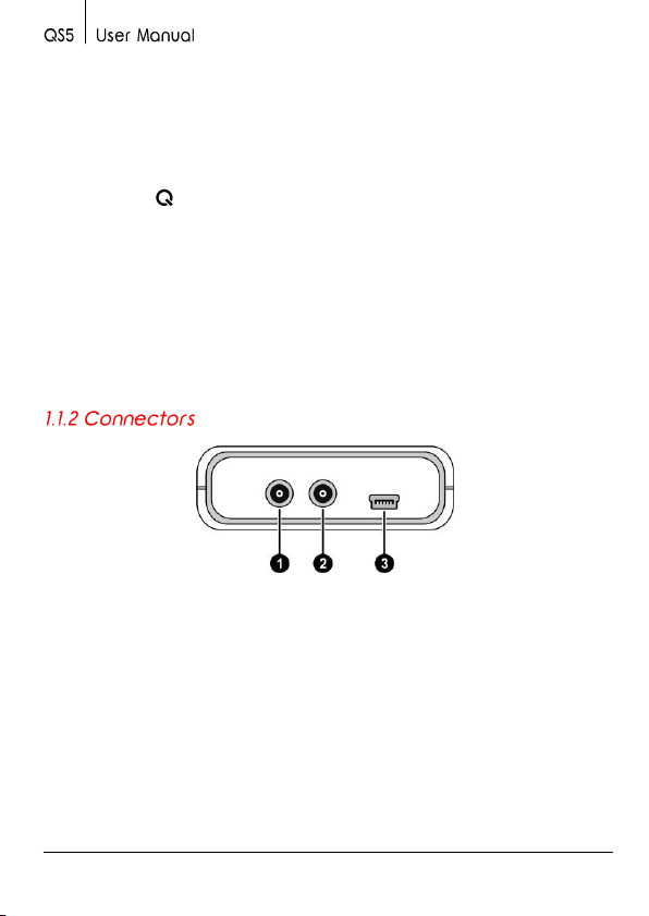
Figure 1.2: Unit connectors
1. Receiving transducer connector (Type Lemo 00)
2. Emitting transducer connector (Type Lemo 00)
3. USB mini connector to connect to PC using a USB cable
(supplied with the unit)
2 Chapter 1
Page 15
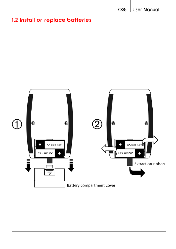
The QS5 is powered by 2 (two) AA batteries that are placed in the
battery compartment located in the back of the unit. To access to the
battery compartment slide the cover as shown in figure 1.3-1 and
gently push the extraction ribbon upward and slightly towards the
right to release the batteries (figure 1.3-2).
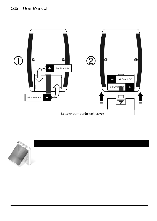
When you install new batteries, first insert the positive end of each
battery so that it coincides with the positive pole inside the battery
compartment as you see in figure 1.4-1. Always leave the extraction
ribbon underneath the batteries.
Figure 1.3: Removing batteries
Chapter 1 3
Page 16
Notes
Use new alkaline top brand batteries only.
Do not mix new and old batteries. Always replace both
batteries.
Rechargeable batteries type NiMH can be used but will
result in less time of continuous operation.
Figure 1.4: Replace / Insert batteries
4 Chapter 1
Page 17
Important
Do not remove batteries while the unit is powered as
this may affect the Datalogger (See Appendix:
“Additional information, Error Messages”)
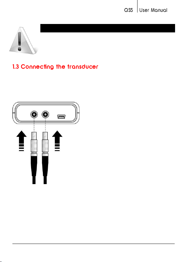
The QS5 has two type Lemo “00” connectors located on top of the
unit. Because this is the standard for most dual crystal probes, you
could basically connect any probe to your QS5. Keep in mind that the
gain may need to be adjusted when changing probes.
To connect the probe, simply align any
of the male connectors located at the
end of the transducer cable to any of
the female connectors located on the
gauge and press gently until
connected.
To release the probe hold the knurled
section on the male connectors and
pull gently away from gauge until
released.
Figure 1.5: Connecting the transducer
Chapter 1 5
Page 18
The has three functions:
When the unit is off, touch for 2 seconds to power on
the unit.
When the unit is on, touch for 2 seconds to shutdown
the unit.
With the unit on, making short touches to the will
activate special functions described in later chapters of this
manual.
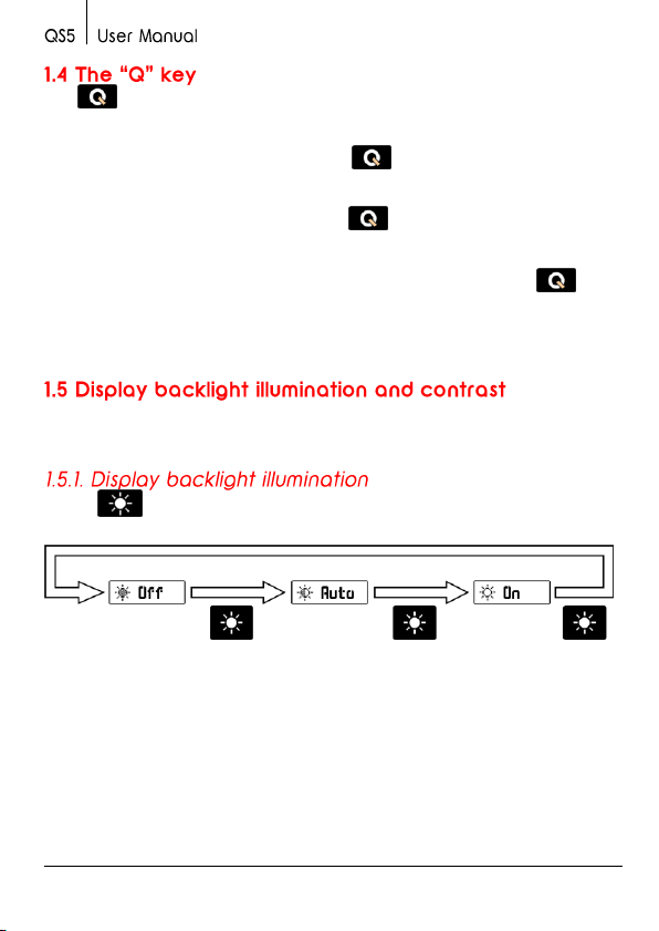
Backlight illumination and contrast options can be changed from any
screen in the unit.
Touch to change the backlight illumination settings.
Figure 1.6: Backlight illumination options
6 Chapter 1
Page 19
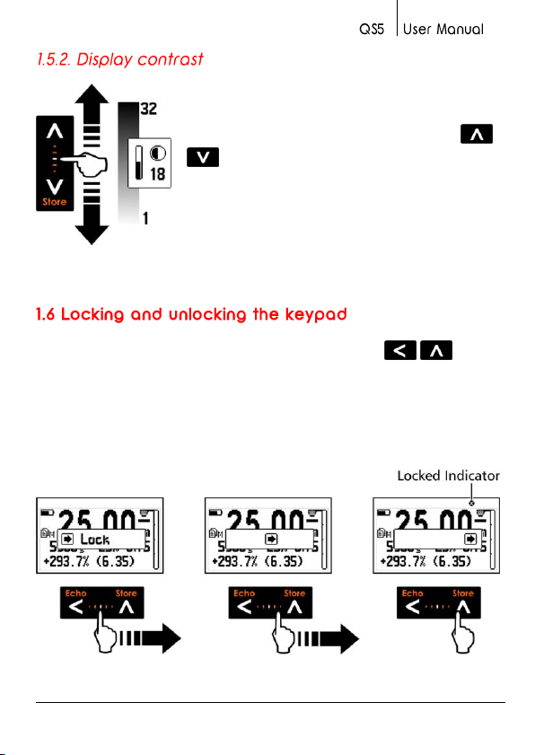
The display contrast on all dmq units is digital.
Touch the white dot located in the center of
the vertical scrolling bar between the -
keys and a contrast window will open.
Move your finger towards the top and or
bottom of the dotted line to adjust the contrast
on your display.
Figure 1.7: Display contrast adjustment
To lock the keypad place your finger on the white dot located in the
center of the horizontal scrolling bar between the - keys.
Move your finger to the right following the dotted line and a window
on the unit display will open with the word Lock. Continue moving
your finger in the same direction until you enter locked mode. The
window on the display will close and the locked keypad indicator will
show on the top right of the unit screen.
Figure 1.8: Locking the keypad
Chapter 1 7
Page 20
\
Important
The keypad can only be locked and unlocked in the
measuring screens.
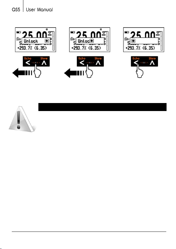
Sliding the finger to the left will unlock the keypad.
Figure 1.9: Unlocking the keypad
8 Chapter 1
Page 21
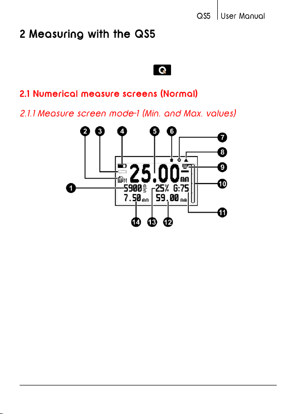
The QS5 can display measurements in 3 distinct numerical measuring
modes or screens each one showing specific information. To switch
numerical measure screens touch the key.
Figure 2.1: Measure screen mode-1
1. Material velocity
2. Datalogger mode indicator (Page 62)
3. Measured value signal in differential measuring mode (Page
44)
4. Battery level indicator
5. Thickness value in the selected unit
6. Icon indicating that a value was stored
7. Locked keypad icon indicator (Page 7)
Chapter 2 9
Page 22
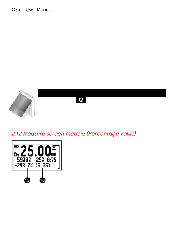
Note
Touching the once will reset maximum and
minimum values to zero and touching it again will
display the measure screen in mode-2 described next.
8. Inactive calibration disk indicator (Page 16)
9. Coupling level indicator / material condition analyzer (Page
21)
10. Echo energy level indicator (Page 22)
11. Gain level (Page 20)
12. Maximum measured value
13. Trigger level (Page 20)
14. Minimum measured value
15. Percentage value as compared to
the nominal value
16. Nominal value (represents 100% of
the percentage value)
Figure 2.2: Measure screen mode-2
10 Chapter 2
Page 23
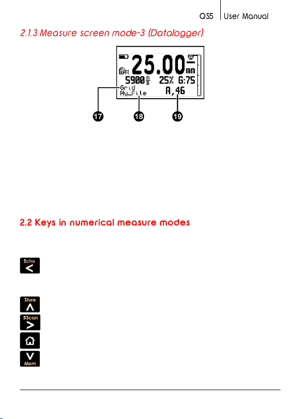
Figure 2.3: Measure screen mode-3
17. Data storage modes (Grid / SCAN)
18. Name of open file where data is being stored (Page 53)
19. Position within the grid of the last stored value (Column,
Row)
In all three numerical measure screen modes the following applies in
terms of keypad functionality:
: Touch once to switch from Echo-1 to Echo-2. Touch again to
switch back to Echo-1 (the Echo key is active only in QS5 E and QS5
DLE models).
: Touch to manually store the measurement in the memory.
: Touch to switch to real time graphic BScan mode.
: Touch to exit the measure screen and enter the main menu.
: Touch to view quick memory access options.
Chapter 2 11
Page 24
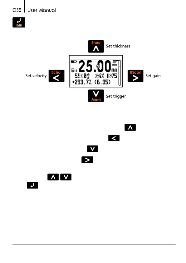
: Touch to activate the Select / Edit mode. Four flashing arrows
will appear over the fields of measurement, velocity, trigger and gain.
Figure 2.4: Measuring screen in select / edit mode
To select thickness measurement touch
To select material velocity touch
To select trigger touch
To select gain touch
Always use the - keys to edit the values in any given field and
touch to save.
Trigger and gain can be edited while measuring. This allows you to see
the new thickness value (resulting from the changes made earlier to
the trigger and gain settings) to be displayed immediately.
12 Chapter 2
Page 25
Note
The measurement field can only be edited if an actual
measurement was taken. If the measurement is 0.00 this
field cannot be edited.
Tips
Touch the when editing velocity and a screen will
appear with the most commonly used materials and
their velocities. Use the cursor keys to scroll the list and
touch to select or touch to exit and return to
the edit velocity field.
When a measurement was taken and the velocity is
changed, a new measurement is automatically displayed
that reflects the change in velocity.
: Short touches allow you to switch between the three measure
screen modes. Touch for 2 or more seconds to shutdown the unit.
: Changes the backlight illumination.
: Adjust display contrast.
Chapter 2 13
: Lock and unlock the keypad.
Page 26
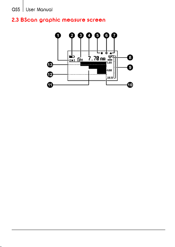
The QS5 allows you to view measured values in real time graphics.
Figure 2.5: BScan graphic
1. Zoom level
2. Battery level indicator
3. Datalogger mode indicator (Page 62)
4. Thickness value in the selected unit
5. Icon indicating that a value was stored
6. Locked keypad icon indicator (Page 7)
7. Inactive calibration disk indicator (Page 15)
8. Coupling level indicator / material condition analyzer
9. Echo energy level indicator
10. Vertical thickness reference axis in the graphic
11. BScan graphic area
12. High alarm setting (Page 31)
13. Low alarm setting (Page 31)
14 Chapter 2
Page 27
Keypad functions in the BScan graphic mode are the same as in the
numerical measure screen modes (Page11) except for the following
keys:
: Go to the numerical measure screen mode
: Short touches will zoom in / out of the graphic. Touch for 2 or
more seconds to shutdown the unit.
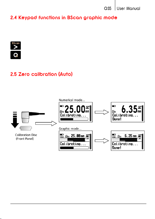
The QS5 uses a zero (delay) calibration procedure that is activated by
simply coupling the transducer over the calibration disk located in
front of the unit.
Figure 2.6: Zero calibration procedure
When this automatic procedure ends, the unit is calibrated to measure
steel which is the default material velocity used in this calibration
method.
Chapter 2 15
Page 28

Tip
In order to measure the thickness of the calibration disk
without activating the automatic calibration procedure
simple touch the edge of the disk until an icon appears
as shown in (Figure 2.1, 8. Inactive calibration disk
indicator, Page 9) While still touching the edge of the
disk, couple the transducer to obtain its thickness
measurement. When the transducer is coupled you no
longer need to touch the edge of the disk.
16 Chapter 2
Page 29
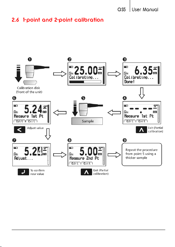
In order to obtain precise measurements, especially when exchanging
transducers, the QS5 can be calibrated with your own test piece
samples. To access the two calibration modes available on the QS5, go
to the Ultrasonic menu (page 43) and enter the Calibr. option. Select
2-Points and follow the procedure below for calibration:
Figure 2.7: One point and two point calibration procedure
1. Measure using the calibration disk located in the unit front
panel.
The unit will proceed with the automatic calibration
procedure and “Calibrating” will be displayed on the unit
Chapter 2 17
Page 30
Notes
In the 2 point calibration procedure, the thickness of the
1st point (first test piece sample) MUST be lower than the
thickness of the second test piece sample.
The unit assumes that the material velocities of the test
piece samples are the same and that the correct velocity
has been set in the unit before the calibration procedure
was initiated.
Use of the unit calibration disk does not change the
velocity set by you.
screen. When the calibration is done, the unit will display
“Calibration… Done!”. At this point the unit will ask that you
measure the first test piece sample “Measure 1st Pt.” and
two additional options will be displayed: Edit and Exit.
2. Touch (Exit) to end the calibration using just the unit
calibration disk, or measure the first test piece sample.
3. After a measurement is displayed touch (Edit) to edit
the value using the cursor keys so that it matches the actual
test piece thickness.
4. When you are done editing the measurement, touch to
save and the unit will ask “Measure 2nd Pt.”.
5. When a measurement is displayed for the second test piece
simple, touch (Edit) to edit the value using the cursor
keys so that it matches the second test piece simple
thickness. When you are done editing the measurement,
touch to end the 2-point calibration procedure.
18 Chapter 2
Page 31
Tip
Touch the when editing velocity and a screen will
appear with the most commonly used materials and
their velocities. Use the cursor keys to scroll the list and
touch to select or touch to exit and return to
the edit velocity field.
If you know the velocity of the material you will be measuring you can
manually enter the velocity by doing the following:
Go to any numerical measure screen mode. If you are in
graphic BScan mode touch (BScan) to switch to normal
mode.
Touch from any numerical measure screen to enter the
Select / Edit mode.
Touch to edit the velocity field.
Use the cursors to set the velocity and touch to confirm
or touch to cancel.
If you do not know the velocity of the material but you know the
material thickness you can set the velocity using the material thickness
value by doing the following:
Measure the material for which you already know the
thickness.
Lift the transducer and touch to enter the Select / Edit
mode.
Chapter 2 19
Page 32
Note
When changing the material velocity using a known
thickness value the unit must have already been
calibrated for the transducer being used (Page 15).
Touch to select the thickness measurement field.
Use the cursors to set the thickness value and touch to
confirm or touch to cancel.
When editing the thickness value observe that the velocity will change
accordingly.
The QS5 has two controls (Trigger and Gain) that have a direct impact
on the ultrasonic signal process so that any dual crystal transducer can
be used and optimized for best performance.
The following image shows you how to interpret changes done to the
trigger level represented in higher and lower trigger values.
Figure 2.8: Representation of high and low levels of trigger
20 Chapter 2
Page 33
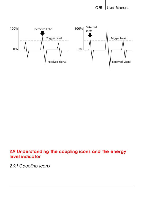
The image below shows how you to interpret changes done to the
gain level represented in higher and lower gain values:
Figure 2.9: Representation of high and low levels of gain
The trigger level determines the echo signals detected by the unit. A
higher trigger means lower sensitivity where only larger echoes are
detected. The gain level works like a “volume control on an audio
device”, the higher the gain setting the more amplified the echoes will
be.
A low trigger and a high gain are ideal in obtaining good sensitivity,
but if the trigger is set too low or the gain too high “noises” are
generated in the transducer that can result in erroneous or unstable
measurements. Transducers that are defective, badly worn or of poor
quality will also produce noises.
By default the unit always indicates whether the transducer is coupled
(measuring) or if the transducer is not coupled (in the air). But when
the analyzer option located in the Ultrasonic menu (page 47) is
Chapter 2 21
Page 34
Important
Material defects that are represented by the coupling
icons serve only as a warning and should not be
interpreted as definitive results. The specific area where
the possibility of a material abnormality is detected
should then be further inspected to confirm or discard
the warning.
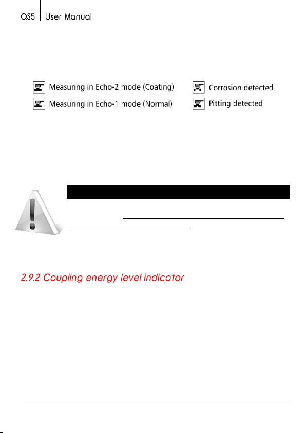
activated the unit now also alerts the operator on the possible
condition of the test piece being measured. When the material
condition analyzer - available exclusively from dmq - is enabled, the
QS5 can display any of the following coupling icons:
Figure 2.10: Coupling icon representations
The analyzer only works in Echo-1 mode. When measuring in Echo-2 or
thru-paint mode the coupling icon will simply indicate that you are
measuring in that mode (represented with two parallel lines).
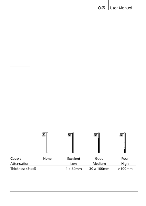
The vertical bar located on the far right side of the measuring screen
shows the echo signal intensity or energy level received by the
transducer giving you valuable information such as:
The coupling condition between the transducer and the test
piece.
The reflective (bottom) test piece surface condition where
22 Chapter 2
low energy levels would typically indicate the possible
presence of corrosion or pitting.
Page 35
The material attenuation level that allows the operator to
detect metal treatments that have an effect on the ultrasonic
characteristics of a material.
The QS5 has two modes for representing the energy absorbed by the
transducer:
No DAC: Shows only the energy level as provided by the transducer
With DAC: Compensates the energy level based on the measured
thickness. Use DAC to detect material conditions such as thermal
treatments and test piece defects easier regardless of the measured
thickness. DAC is activated in the Ultrasonic menu (page 47).
The higher the energy level reflected from the test piece bottom, the
higher the energy level will be on the vertical bar. This is an indication
of good coupling.
Low energy indicates any of the following: poor coupling (not enough
coupling gel), high attenuation materials (treated metals and some
plastics), an irregular test piece bottom surface (possible corrosion or
pitting) or if DAC is disabled it may be reflecting the test piece
thickness.
Figure 2.11: Vertical bar energy level representations
Chapter 2 23
Page 36

Tips
Sudden intensity loses usually mean that there are
defects in the test piece related to corrosion or pitting.
When measuring thick test pieces with DAC turned off,
the energy level decreases because a greater distance
(thickness) usually results in more attenuated echoes
being received by the transducer.
When a test piece made of steel that will typically return
high energy levels, is returning low energy, this usually
means that it was subject to thermal treatment. To
confirm or discard this possibility, measure the velocity
of the test piece. Steel that has been thermally treated
will have a different material velocity.
In case of low energy levels always make sure you have
good coupling and that you used enough coupling gel
to avoid erroneous interpretations.
When measuring in Echo-2 or thru-paint the energy level
may be low because the unit uses the energy produced
by the second echo which is normally smaller and more
attenuated when compared to the first echo used in
normal Echo-1 measurements.
24 Chapter 2
Page 37
The QS5 E and QS5 DLE gauges can measure thru-coatingings such as
paint or epoxy so you no longer need to scrape and remove the
coating in a test piece. The unit now “skips” the coating and measures
only the actual test piece thickness.
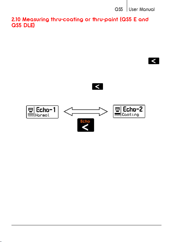
To enable thru-coating or thru-paint mode (Echo-2) touch the
(Echo) key from the measuring screen and the unit will display the
mode you are in. (Echo-1 normal, or Echo-2 coating (thru-paint).
Switch between Echo modes touching and wait until the window
indicating the mode you are in disappears. This means that the unit is
now set for the Echo mode you selected.
Figure 2.12: Change of Echo windows (normal or coating)
Multi-echo units use separate ultrasonic configurations for each echo
mode. This means that when switching between Echo-1 and Echo-2
modes the gain, trigger and voltage of the pulse emission are
maintained for each mode. In the example below the gain level for
Echo-1 is 75 and for Echo-2 it is 63. These gain levels will not change
as you switch modes.
Chapter 2 25
Page 38
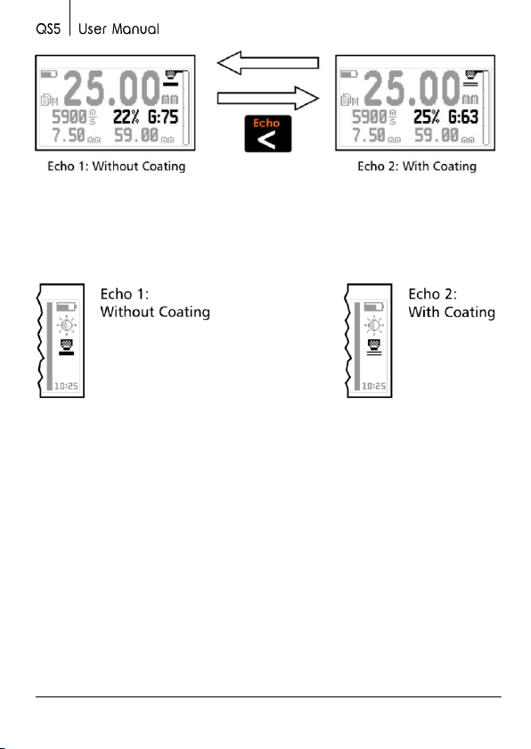
Figure 2.13: Ultrasonic settings on each echo mode
All unit menu screens display an icon indicating the echo mode that
the unit is operating in.
Figure 2.14: Echo mode icon in menu screens
In Echo-2 mode the unit does not need to be calibrated and calibration
is actually blocked because when operating with multiple echoes the
delay in the transducer does not affect the thickness measurement.
To obtain precise and reliable measurements in Echo-2 mode the
following considerations and limitations should be considered:
The test piece coating should not exceed 2mm. This may vary
according to the attenuation of the coating material.
The thickness of the actual test piece should not exceed
25mm.
26 Chapter 2
Page 39

Lose or poor adherence between the coating and the test
piece can result in scattering of ultrasonic waves making it
impossible to measure.
Use sufficient coupling gel for stable coupling in order to
avoid erroneous or incorrect readings.
Always use dmq hi-damp transducers to measure in Echo-2
mode. Standard probes will not work correctly in this mode.
Chapter 2 27
Page 40
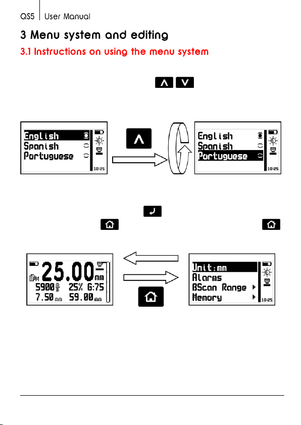
The instructions explained in this chapter apply to all of the menus in
the unit.
To scroll QS5 menu options use the - cursor keys. When you
reach the end of the menu and move to the next menu option it
becomes circular as shown below.
Figure 3.1: Example of how a circular menu works
To select a menu option touch and to exit and return to the
previous menu touch . To go to the measuring screen touch
from the main menu.
Figure 3.2: The “Home” key from the measuring screen
28 Chapter 3
Page 41
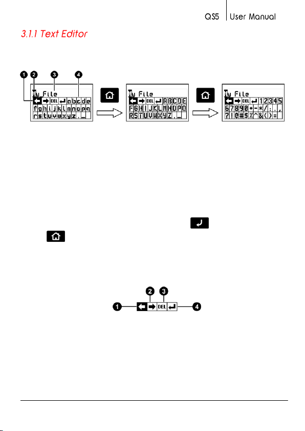
The text editor is used to input, change, and delete; letters, numbers
and symbols.
Figure 3.3: Alphanumeric editor screens
1. Selected key
2. Cursor
3. Text to be edited
4. Virtual keyboard
Use the cursor keys on the unit to scroll the virtual keyboard until you
find the character you want to use and touch to select.
Touch to move to the upper case virtual keyboard and to the
numbers and symbols keyboard as seen on figure 3.3.
There are 4 keys that are common to all virtual keyboard screens:
Figure 3.4: Common virtual keyboard keys
1. Move cursor to the left
2. Move cursor to the right
Chapter 3 29
Page 42
3. Erase the character on which the cursor is on
4. Enter and exit
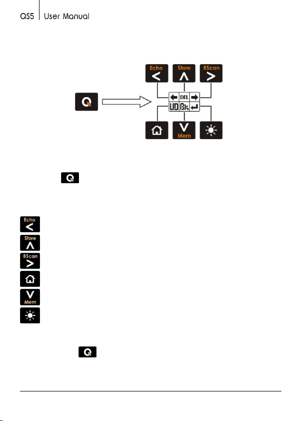
Figure 3.5: Quick access keys for the virtual keyboard editor
Touch the key to open the quick access keyboard to the most
commonly used virtual keyboard keys. Each virtual key corresponds to
a key on the front panel of the unit as follows:
: Move the cursor to the left
: Erase the character on which the cursor is on
: Move the cursor to the right
: Undo
: Erase the character to the left of the cursor
: Enter and exit
To close the quick access keyboard and continue using the virtual
keyboard touch .
30 Chapter 3
Page 43
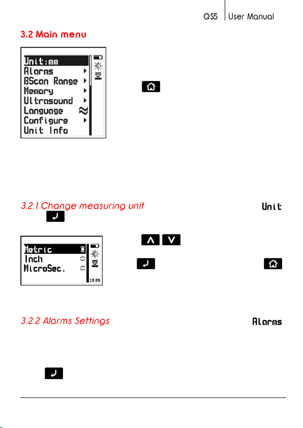
The main menu is the first list of options that
appears when you exit the measure screen
and it includes the most important settings.
Touch from the measuring screen to
access this menu.
Figure 3.6: Main menu
Note: The options of Configure, Ultrasonic and Memory are explained
later on in this manual.
Touch on Unit in the main menu to open the list of available
units.
Use the - keys to scroll the menu.
Touch to select the unit and touch
to save and exit this menu.
Figure 3.7: Units menu
The QS5 has high and low alarms that alert the operator when the
measurement is greater than the value set for the high alarm and or
when the measurement falls below the value set for the low alarm.
Touch on Alarms to open the alarm menu options.
Chapter 3 31
Page 44
Note
The material condition analyzer operates only in Echo-1
mode. In Echo-2 or thru-paint mode the flaw alarm is
automatically disabled.
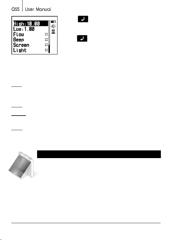
Touch on High or Low to open the
numbers editor where you can set alarm
values using the cursor keys.
Touch to save the alarm value that you
entered and to return to the previous menu.
Figure 3.8: Alarms menu options
Any of the following alarm types can be selected:
Flaw: The alarm is activated when the material condition analyzer
detects the presence of a possible defect such as corrosion or pitting.
Enabling this option will activate the Analyzer (page 49).
Beep: Audible intermittent alarm type.
Screen: Visible alarm that causes measurements to be displayed in
dotted instead of regular numbers.
Light: Visible alarm that activates the display backlight illumination
causing it to flash.
32 Chapter 3
Page 45
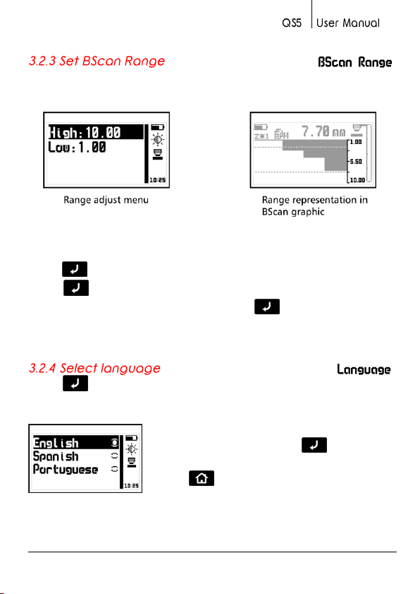
Here you can set high and low values (thickness range) that will be
represented on the vertical axis of the graphic BScan measure screen.
Figure 3.9: BScan range and graphic representation
Touch on BScan Range to open the menu.
Touch on High or Low to open the numbers editor where you
can set a value using the cursor keys. Touch to save and return to
the previous menu.
Touch on Language (which is also identified with a flag) to view
available language options.
Use the cursor keys to scroll available
language options and touch to select.
Touch to save and exit this menu.
Figure 3.10: Language menu options
Chapter 3 33
Page 46
Note
The information required to obtain model upgrade
licenses is included in this option.
Select Unit Info to view information including owner data as well as
the software version that your unit is running.
To view different unit information screens touch the - keys.
To return to the main menu touch .
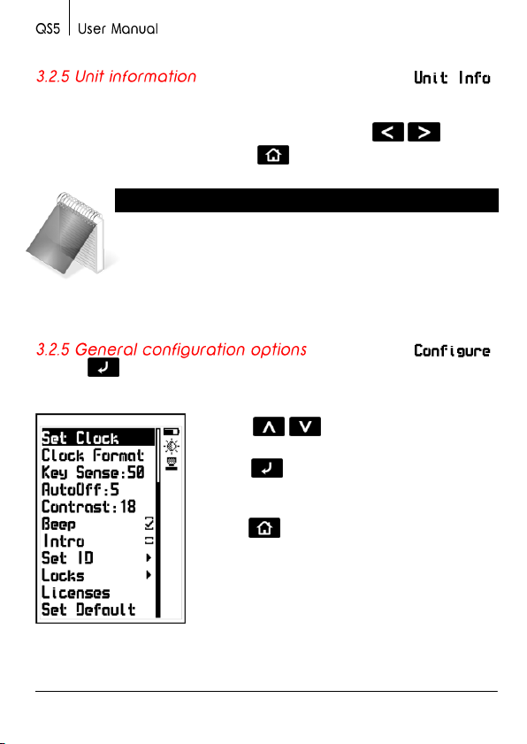
Touch on the Configure option to open the general
configuration options menu.
Use the - keys to scroll the menu.
Touch to select any of the menu
options.
Touch to exit and to return to the
previous menu.
34 Chapter 3
Figure 3.11: General configuration options menu
Page 47
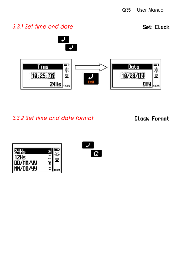
Choose Set Clock to open the time editor and use the cursor keys to
set the time. Touch to save and to enter the date editor screen.
Set the date and touch to save and exit.
Figure 3.12: Time and date editing screens
Choose Clock Format to open the menu that allows you to set the
time format (12Hs or 24Hs) and the date format (D/M/Y – M/D/Y).
Touch on the option you wish to select
and touch to save and exit.
Figure 3.13: Date and time format menu options
Chapter 3 35
Page 48
Tips
If the unit will be operated using security gloves we
recommend that the sensitivity level be raised.
To make the keypad “harder” simply lower the sensitivity
level.
In applications where the front of the unit may be
exposed to water and or vapors the sensitivity should be
lowered.
This option allows you to set the keypad sensitivity. The higher the
number is that you set here, the more sensitive the keypad will be.
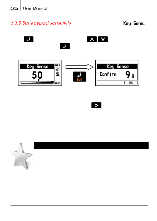
Touch on Key Sens. and use the - keys to change the
keypad sensitivity. Touch to save and the keypad will already be
working with the new sensitivity level.
Figure 3.14: Key sensitivity and confirmation screens
To confirm the change in sensitivity touch . If you touch any other
key or the counter that appears on your screen reaches 0.0, the
sensitivity will return to its previous setting.
The factory default setting is 50. Under special conditions we suggest
that the sensitivity level be changed.
36 Chapter 3
Page 49
The unit will shutdown automatically if no key is touched or no
measurement is made when you set the auto-off time.
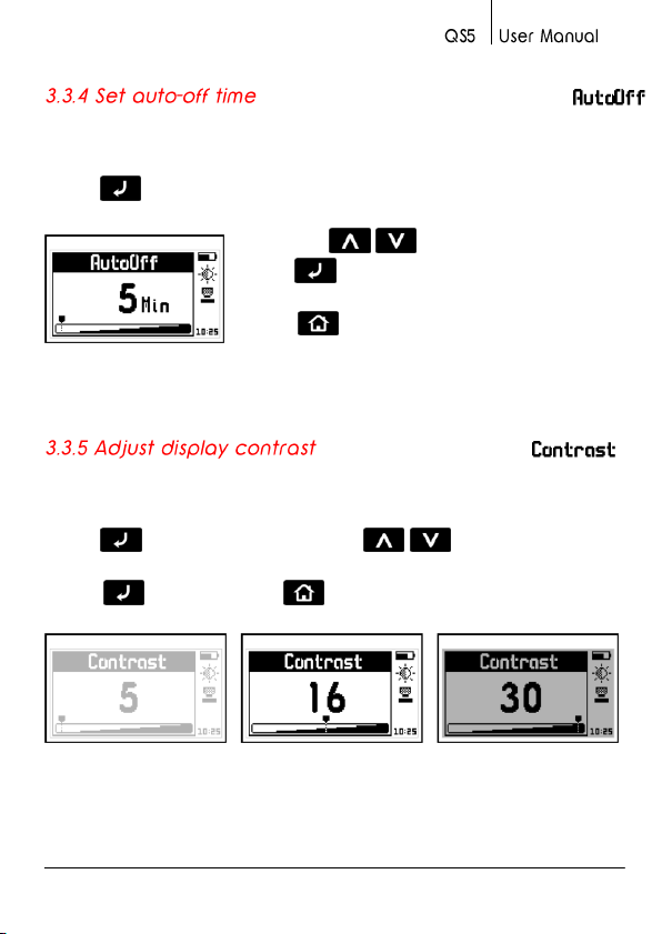
Touch on AutoOff to set the time before the unit automatically
shutdown.
Touch the - keys to set the time and
touch to save and exit.
Touch to exit without making changes.
Figure 3.15: Auto-off time setting screen
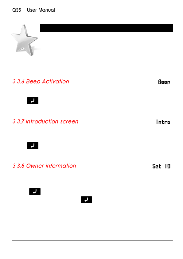
Use this setting to adjust the screen contrast making it lighter or
darker where 1 is the lightest and 32 is the darkest.
Touch on Contrast and use the - keys to change the
contrast on your screen.
Touch to save or touch to exit without making changes.
Figure 3.16: Screen contrast settings
Chapter 3 37
Page 50
Tips
Contrast on LCD screens can change with temperature.
Use the contrast option to compensate for changes
caused by temperature in order to maintain optimal
viewing conditions.
Beep refers to the sounds that the unit makes when keys are touched
and when the audible alarm is activated.
Touch to enable or disable the beep option.
The introduction screen is the first screen that you would see (if this
option is enabled) after the unit is turned on. It includes owner
information such as name, telephone number and e-mail.
Touch to enable or disable this option.
This option allows you to enter owner information (the info that would
appear on the introduction screen).
Touch on Set ID, enter the password (the factory default
password is 12345) and touch to access user info menu options.
38 Chapter 3
Page 51
Notes
When showing user information, the e-mail address is
displayed as "Name@Domain".
Important
The factory default password is 12345. You can change
this password after adding your user information.
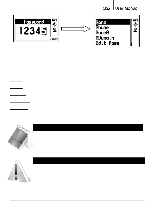
Figure 3.17: Enter password to access the user info menu
The user information that can be added or changed at anytime
includes the following:
Name: Set or change the owner name.
Phone: Set or change the telephone number.
Name@: Set or change the e-mail (before the @).
@Domain: Set or change the domain for the e-mail (after the @).
Edit Pass: Allows you to change the password needed to access this
menu.
Chapter 3 39
Page 52
Certain configuration options on your QS5 unit can be locked in order
to avoid unwanted changes. Use of the locking options allow a
supervisor to optimize unit configuration settings required for a
specific test and then pass the unit on to an operator for him or her to
conduct the actual measurements knowing that the unit has been
properly configured and that the settings cannot be changed.
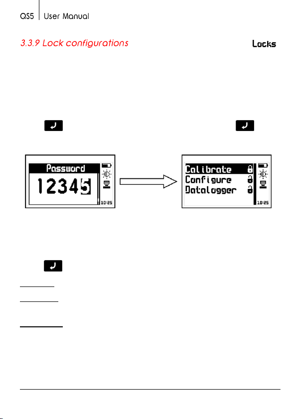
Touch on Locks, enter your password and then touch again
to view the configuration options that can be locked.
Figure 3.18: Enter password and options lock menu
Each option is followed by a lock indicating whether the feature is
locked (closed lock) or unlocked (open lock).
Touch on each of the following options to lock or unlock:
Calibrate: Lock or unlock unit calibration options.
Configure: Lock or unlock ultrasonic configuration options (trigger
and gain).
Datalogger: Lock or unlock Datalogger configuration options.
40 Chapter 3
Page 53
QS5 models can be changed with software licenses that you can
purchase from dmq. If you want to purchase an upgrade license we
will need to know the following information:
Unit model
Unit serial number
The type of license that you would like to purchase
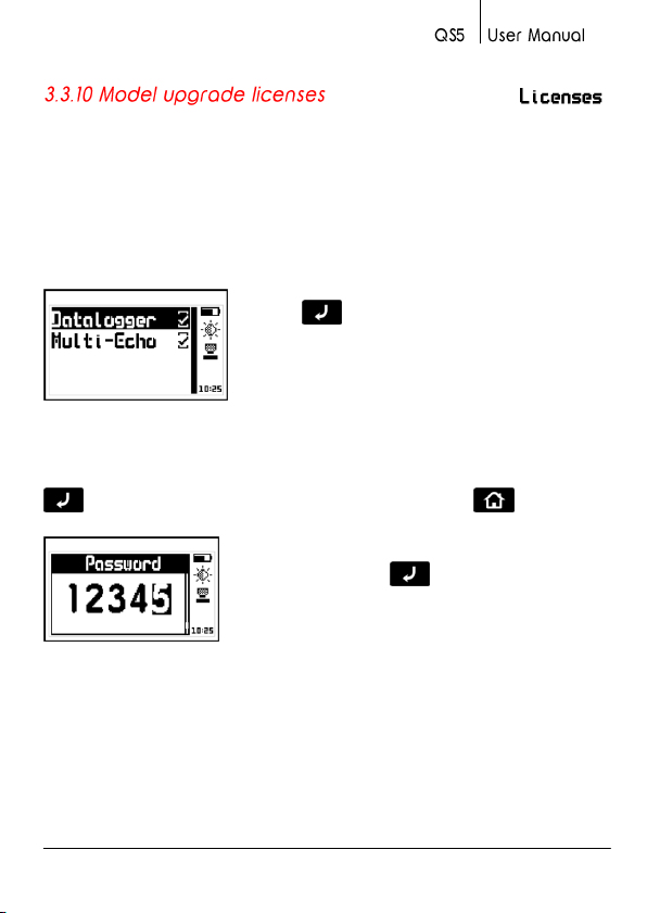
Touch on Licenses to view all licenses
available for your unit (checkmarks indicate
active licenses).
Figure 3.19: Licenses screen
To enter the new license number that you purchased from dmq touch
or to exit and return to the previous menu touch .
Use the cursor keys to enter the license
number and touch to save.
Figure 3.20: Enter new license number screen
After you enter the new license number the unit will respond with one
of the following messages:
Chapter 3 41
Page 54
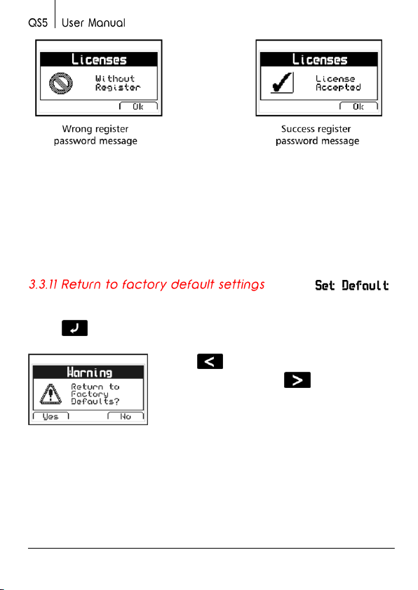
Figure 3.21: Response messages after a license is entered
If the license number that you entered is correct the unit will show an
updated license screen where the newly purchased license appears
followed by a checkmark.
Choose Set Default to return to the original factory default general
configuration options.
Touch and a confirmation screen will appear.
Touch to confirm and return to the
previous menu or touch to exit without
making changes.
Figure 3.22: Set factory default settings confirmation screen
42 Chapter 3
Page 55
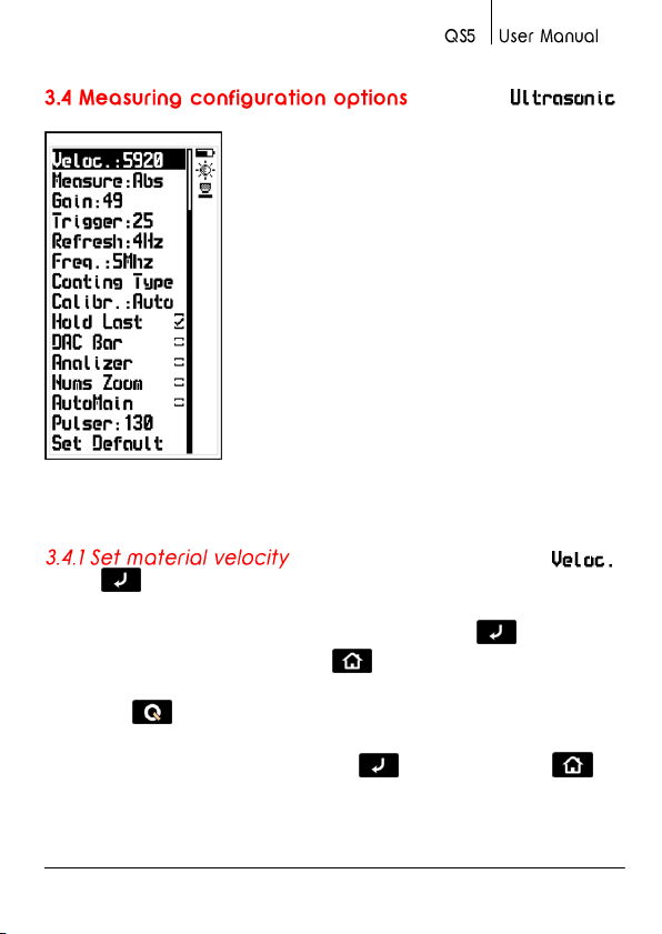
Select Ultrasonic from the main menu to
display measuring configuration options.
Setting these options correctly is critical in
attaining reliable measurements.
Figure 3.23: Measuring configuration options menu
Touch on the Veloc. option to change the material velocity so
that it matches the material that will be measured.
Use the cursor keys to change the velocity and touch to enter. To
exit without making changes touch .
Touch the when editing velocity and a screen will appear with a
list of the most commonly used materials and their velocities. Use the
cursor keys to scroll the list and touch to select or touch to
exit and return to the edit velocity field.
Chapter 3 43
Page 56
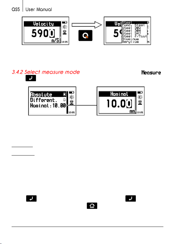
Figure 3.24: Change material velocity and material velocity list
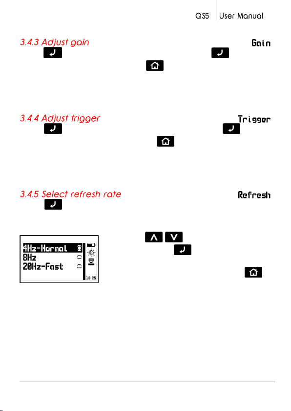
Touch on Measure to open the measure modes options menu.
Figure 3.25: Measure mode options menu and set nominal value
The modes in which measurements are represented are:
Absolute: the unit displays the real measured value
Different.: the displayed value is the result obtained from calculating:
Where the nominal value is a reference value for the test piece
Touch on Nominal to set this value and touch to save. To
exit without making changes touch .
Differential = Real value – Nominal value
44 Chapter 3
Page 57
Touch on Gain to change this value and touch to save. To
exit without making changes touch .
For additional information on setting the gain refer to "Changing
trigger and gain" (page 20).
Touch on Trigger to change this value and touch to save.
To exit without making changes touch .
For additional information on setting the gain refer to "Changing
trigger and gain" (page 20).
Touch on Refresh to open the refresh rate options menu (the
speed in which measurements will be taken).
Use the - keys to scroll menu
options and touch to select.
To exit without making changes touch .
Figure 3.26: Refresh rate speed options
The factory default for this setting is 4 Hz (4 measurements per
second) which is enough for most applications. When looking for
additional details or for scanning a specific test piece section we
recommend switching to higher refresh rates.
Chapter 3 45
Page 58
Notes
A higher refresh rate increases energy consumption
therefore reducing battery life.
Storing measurements in the Datalogger at high speeds
means the size of the memory is reduced a lot quicker.
Measuring at 20Hz over one minute is equal on average,
to 1200 measurements.
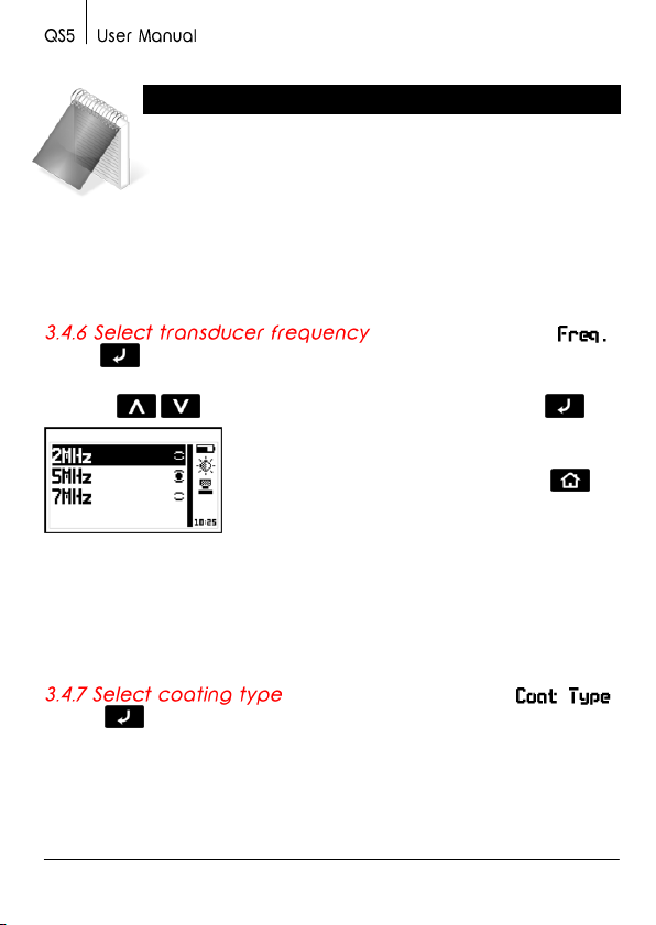
Touch on Freq to open the transducer frequency rate options
menu.
Use the - keys to scroll menu options and touch to
select.
To exit without making changes touch .
Figure 3.27: Transducer frequency options
Most standard transducers are 5MHz. When a different frequency
transducer is used you should select the correct frequency in this
menu.
Touch on Coat Type to open the menu options for the
attenuation level of the coating type when measuring in Echo-2 or
thru-coatinging.
46 Chapter 3
Page 59
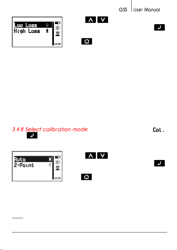
Use the - keys to choose any of the
two available menu options and touch
to select. To exit without making changes
touch .
Figure 3.28: Type of coating options
To measure thru-coatingings that are less than 1mm thick, select the
Low Loss option. For high attenuation coatings such as epoxy
(typically used in shipyards) and for coatings greater than 1mm thick,
select the High Loss option.
Even though the coating type option is available for all QS5 models
this setting only affects the QS5 E and QS5 DLE models that can
operate in Echo-2 mode or thru-coatinging.
Touch on Cal. to open the unit calibration menu options in the
measuring screen.
Use the - keys to choose any of the
two available menu options and touch
to select. To exit without making changes
touch .
Figure 3.29: Unit calibration menu options
The QS5 has two calibration modes:
Auto: Calibration is automatically done when coupling the transducer
using the calibration disk located in the front of the unit (page 15).
Chapter 3 47
Page 60
2-Point: Calibration is done with one or two test piece samples of a
known thickness, and made of the same material that you will be
measuring (page 17). The 2-Point calibration will usually result in more
precise thickness measurements.
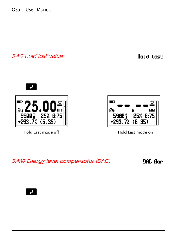
When you enable the Hold last option the last measured value will be
displayed on the unit screen even when the transducer is not coupled.
When hold last is disabled and the transducer is not coupled the unit
display will read "--.--".
Touch to enable or disable this option.
Figure 3.30: Measuring screens with hold last enabled or disabled
When the DAC Bar option is enabled the unit compensates the energy
level on the vertical energy bar based on measured thickness (page 22).
When this option is disabled the energy level on the vertical bar is
shown just as provided by the transducer.
Touch to enable or disable this option.
48 Chapter 3
Page 61
Important
Material defects that are represented by the coupling
icons serve only as a warning and should not be
interpreted as definitive results. The specific area where
the possibility of a material abnormality is detected
should then be further inspected to confirm or discard
the warning.
Note
Activating the flaw alarm (page 32) will automatically
enable the analyzer option.
Enable Analyzer so that the unit will alert the operator on the
presence of possible defects with icons that appear on the measuring
screen (page 21). When the analyzer option is disabled the coupling
icon only indicates whether the transducer is coupled (measuring) or
not coupled (in the “air”).
Touch to enable or disable this option.
Chapter 3 49
Page 62
Note
Enabling the continuous measuring monitor slightly
increases battery consumption. By default this option is
disabled.
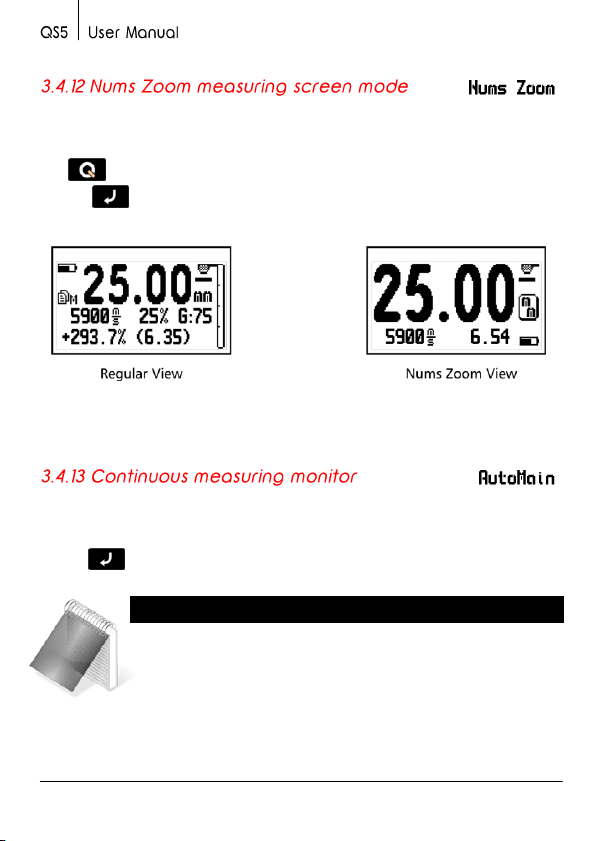
When Nums Zoom is enabled the numerical measuring screen displays
thickness measurements in larger numbers and only the velocity and
minimum value are displayed. The minimum value is reset by touching
the key.
Touch to enable the Nums Zoom option and touch again to
disable.
Figure 3.31: Normal and Nums Zoom numerical measure screens
When AutoMain is enabled the unit continuously monitors the
transducer so that when the transducer is coupled it automatically
switches to the measuring screen regardless of the menu you are in.
Touch to enable or disable this option.
50 Chapter 3
Page 63
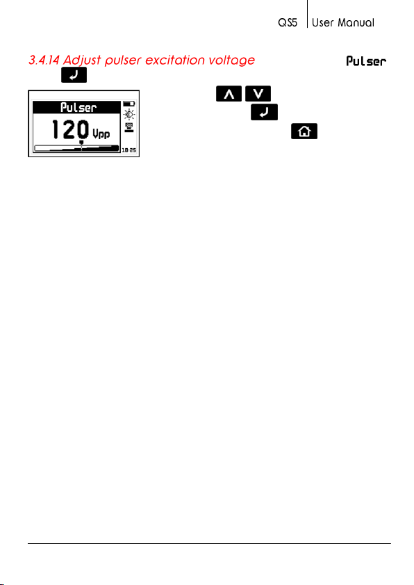
Touch on Pulser to adjust the transducers pulser excitation level.
Touch the - keys to adjust the
tension and touch to save and exit. To
exit without changes touch .
Figure 3.32: Transducer pulser excitation tension editor screen
Just like with the trigger and gain settings the pulser tension is set
separately for Echo-1 and Echo-2 modes.
Considerations when adjusting the pulser excitation tension:
Higher excitation or tension levels mean that more energy is applied to
the emissions crystal in the transducer making it easier to measure in
high attenuation and large or thick materials.
When measuring small or thin materials high tensions produce
saturated echoes that can affect measurement results particularly
when operating in Echo-2 mode.
Avoid high tensions particularly when using small diameter transducers
as this could damage the transducer. For 5MHz transducers the
tension should not exceed 150V. Large diameter transducers of a lower
frequency can be set to higher tensions for better performance.
Chapter 3 51
Page 64
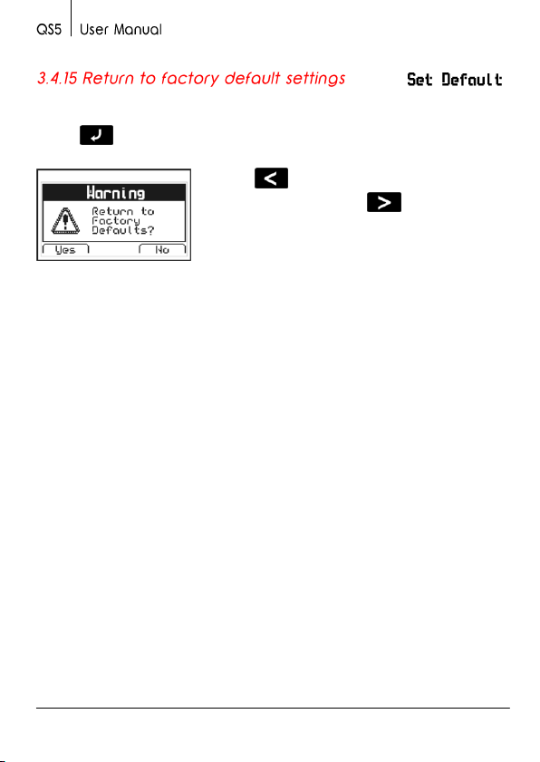
Choose Set Default to return to the original factory default ultrasonic
configuration settings.
Touch and a confirmation screen will appear.
Touch to confirm and return to the
previous menu or touch to exit without
making changes.
Figure 3.22: Set factory default settings confirmation screen
52 Chapter 3
Page 65
In order to optimize the use of the Datalogger in your QS5 DL and QS5
DLE it is important that you understand how data is organized.
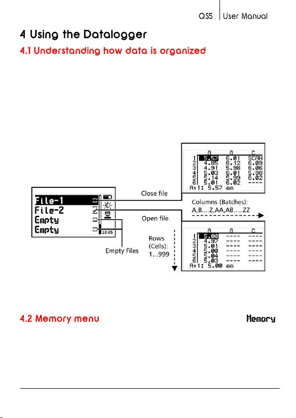
In the QS5 data is stored in 8 individual files with alphanumeric names.
Each file contains a grid with columns and rows. And each grid
contains columns (identified with consecutive letters; A, B, …AA, AB…)
that store an “N” number of values or measurements (batch). Each
value is identified with a column letter and a row number.
Figure 4.1: How data is organized in the Datalogger
Select Memory from the main menu to view all menu options for the
Datalogger. The options in this menu will be different depending on
your QS5 model. The QS5 B and QS5 E store values that can only be
viewed on the unit screen but cannot be sent to a PC or a printer.
Chapter 4 53
Page 66
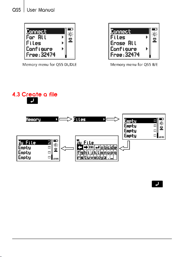
Figure 4.2: Memory menu options based on unit model
Touch on Files and use the cursor keys to navigate the list of files
in the unit.
Figure 4.3: Creating a file
Select a file that appears as Empty (available file) and touch to
name the file with up to 10 alphanumeric characters.
After you enter a name a checkmark will appear next to it meaning
that a new file has been created and is ready to be used.
54 Chapter 4
Page 67
Remember that only one file can be open at any given time so
whenever a new file is created, if a file was already open, the file that
was open will be closed. Once a file has been closed, it cannot be
reopened and new values can no longer be stored. In closed files,
values can only be viewed.
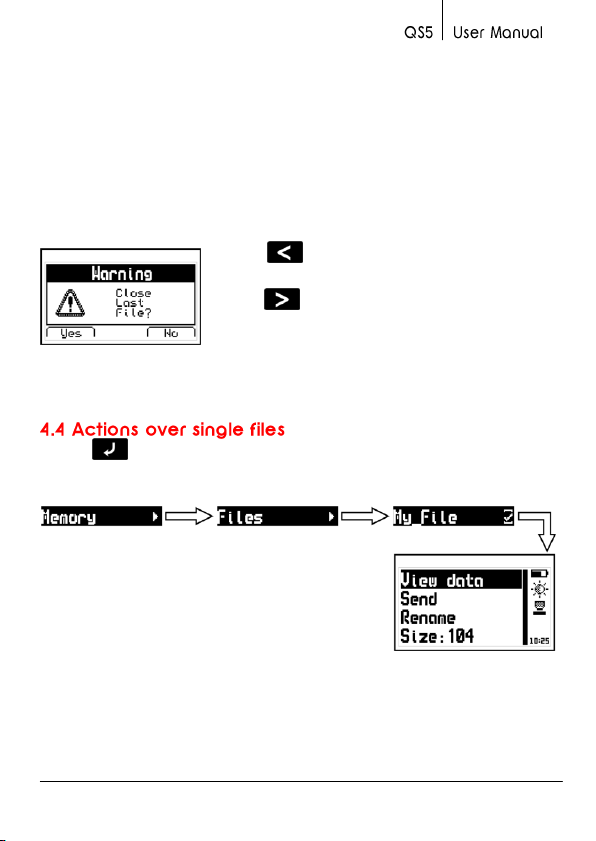
Whenever you create a new file, and another file is already open, a
warning screen will ask if you want to close the last file.
Touch to confirm that you want to close
the open file to create (open) a new one or
touch to cancel and return to the menu.
Figure 4.4: Close file confirmation screen
Touch on any closed file and a menu will open that displays
options for that file.
Figure 4.5: Single file menu options
Chapter 4 55
Page 68
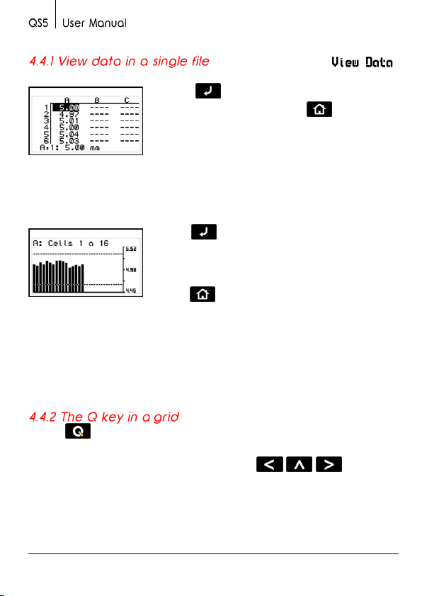
Touch on View Data to view the
contents of the file. Touch to exit the
file.
Figure 4.6: File view in a grid format
To move inside the grid use the cursor keys.
Touch on a value to open a histogram
that includes that same value as well as the
values included in the foregoing cells within
that column.
Touch to exit and return to the grid.
Figure 4.7: Histogram representation
High and low alarm values appear in the histogram as dotted
horizontal lines.
Touch to open the quick access menu that allows you to go
directly to a position inside the grid.
Select the Row, Column, and Cell using the - - keys.
56 Chapter 4
Page 69
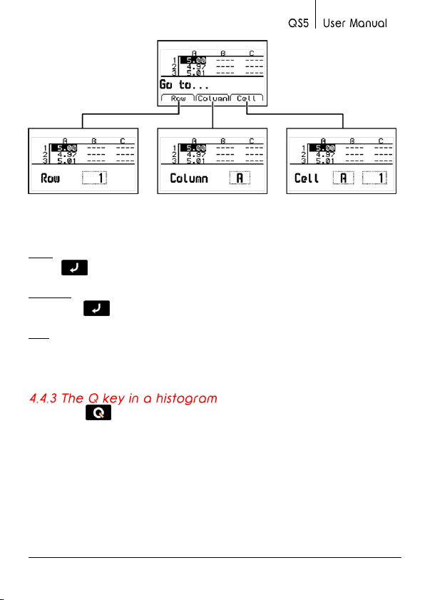
Figure 4.8: Quick access menu options in a grid
Row: Enter a row number using the cursor keys so that when you
touch the grid will position itself directly on that row.
Column: Enter the column letter using the cursor keys so that when
you touch the grid will position itself on that column.
Cell: This is a combination of (column and row) so that you can go to
a specific cell after you enter the row number and column letter.
Touch the key in the histogram to open the quick access menu
that allows you to obtain statistical information on the batch of values
being displayed.
Chapter 4 57
Page 70
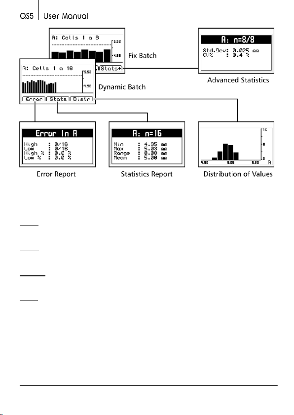
Figure 4.9: Quick access menu options in a histogram
Error: Displays the number of errors and error percentage values in the
batch based on the high and low alarm settings.
Stats: View statistical information for the batch including Min., Max.,
Range and Mean values.
Stats+: View the standard deviation and the percentage (coefficient
variation) for the batch.
Distr: Displays the distribution of values for the batch in a graphic
format (dynamic batch).
58 Chapter 4
Page 71
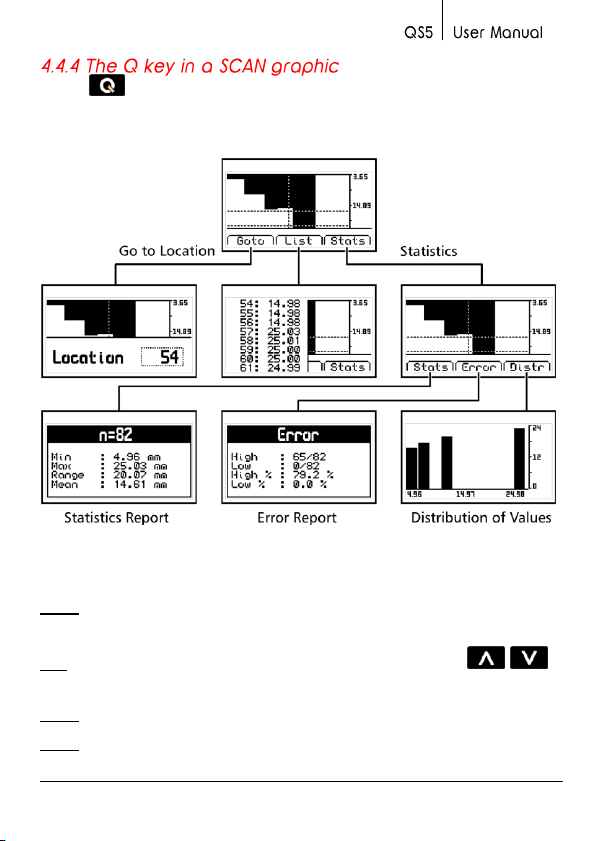
Touch on a SCAN cell to open the quick access menu that allows
you to easily move inside the scan and to view statistical information
on the scan.
Figure 4.10: Quick access menu in a scan graphic
Goto: Access a specific position within the scan by entering its location
(List).
List: Opens the list of measured values in the scan (use the -
to scroll)
Stats: View the options of Stats, Error and Distr.
Stats: View statistical information including Max., Min., Mean and
Range of all values within that SCAN cell.
Chapter 4 59
Page 72
Error: Displays the number of errors and error percentage values in the
scan based on the high and low alarm settings.
Distr: displays the distribution of values for the scan in a graphic
format.
Touch on Send File to send (units with Datalogger only) a single
file to a PC using Windows HyperTerminal, or to a printer using an
RS232 connection. This option does not work in USB mode.
Touch on Rename to open the text editor that allows you to
change the file name.
Touch on Size to view the number of stored values within a
single file (and the size of the file as a percentage of total unit
memory). You can also view the date and time in which the file was
created.
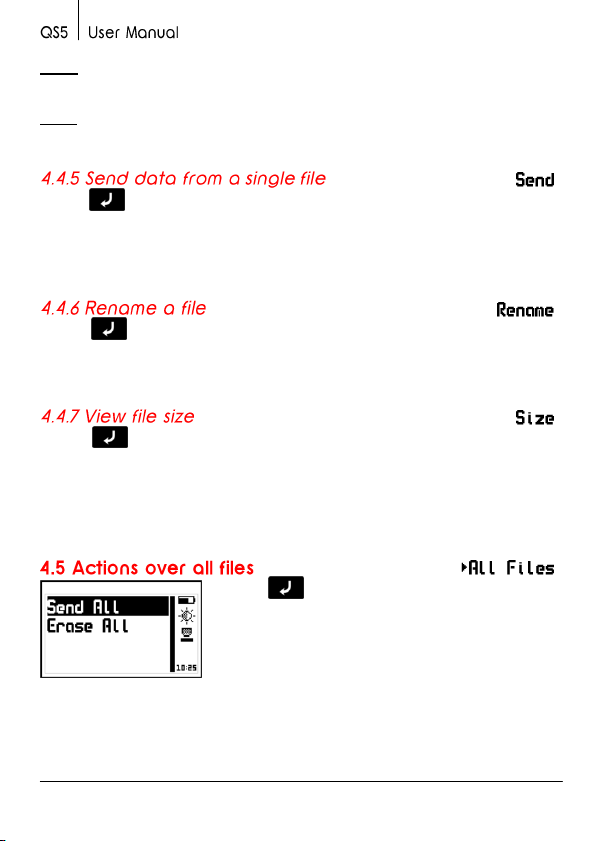
Touch on All Files to open the menu for
actions that will affect all files stored in the
unit memory.
Figure 4.11: Actions over all files menu
60 Chapter 4
Page 73
Touch on Send All to send (units with Datalogger only) all files
stored in the unit memory to a PC using Windows HyperTerminal, or to
a printer using an RS232 connection. This option does not work in USB
mode.
The Erase All action permanently deletes all files stored in the unit
memory and recovers 100% of the memory capacity.
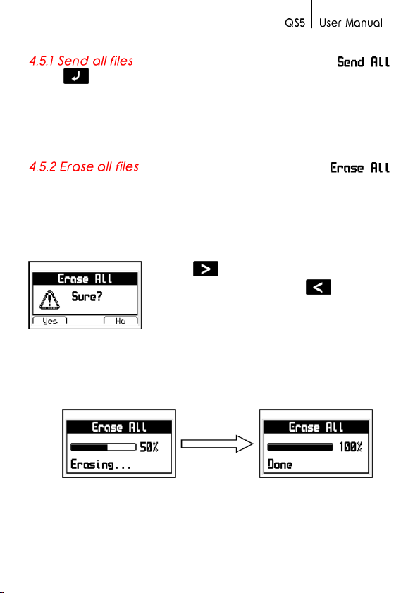
Before files are deleted, a screen will be displayed asking you to
confirm or to cancel this action.
Touch to cancel and return to the
previous menu or touch to begin
deleting all files.
Figure 4.12: Erase all confirmation screen
When the erase all action has been confirmed the following screens
will be displayed:
Figure 4.13: Erase all progress screen
Chapter 4 61
Page 74
X
Datalogger is disabled (no open file)
M
Manual capture mode
U
Single auto capture mode
C
Continuous auto capture mode
S
SCAN block capture mode
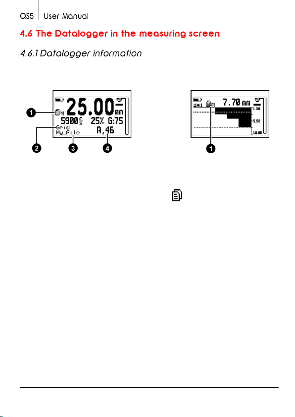
The QS5 Datalogger measure screen includes information and options
to assist you in storing data.
Figure 4.14: Information in the Datalogger measure screen
1. Datalogger status indicator icon followed by any of the
following letters:
2. Storage type (Grid or SCAN). If measurements are being
stored in a grid, “Grid” will be displayed. When a SCAN is
stored the display will read “Scan: N” where N is the position
of the scan block in the grid.
3. Name of the open file
4. Position of the stored value within the grid (Column, Row)
62 Chapter 4
Page 75
Notes
The Datalogger status indicator can be viewed on all QS5
measure screens as well as in the graphic screen.
If no file is open the Datalogger will display “No File”
and the unit will automatically switch to the Min. Max.
numerical measure screen mode.
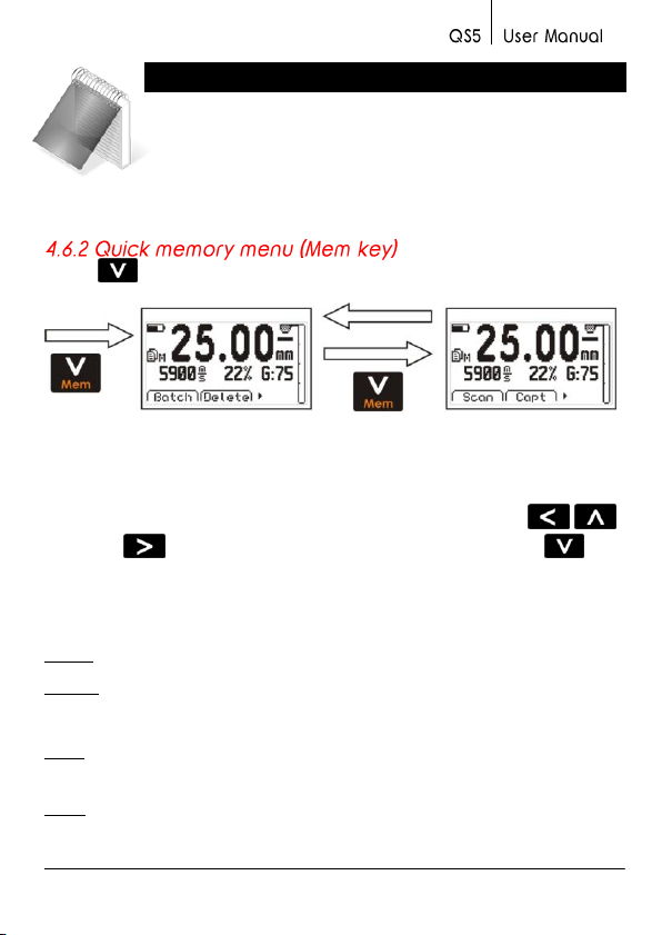
Touch on the measuring screen to open the quick memory menu.
Figure 4.15: Quick memory menu options
In each quick memory menu screen two options are displayed at the
bottom of each screen. To access these options use the -
keys. The key maintains its normal functionality and the key
is used to switch quick screens as seen on figure 4.15.
Options in the first quick memory screen:
Batch: Close the open batch and open a new one.
Delete: Erase the last stored value
Options in the second quick memory screen:
Scan: Opens a SCAN block. If one is already open no action will be
made.
Capt: Changes the capture modes (Manual – Single – Continuous).
Allows you exit the Scan mode as well.
Chapter 4 63
Page 76
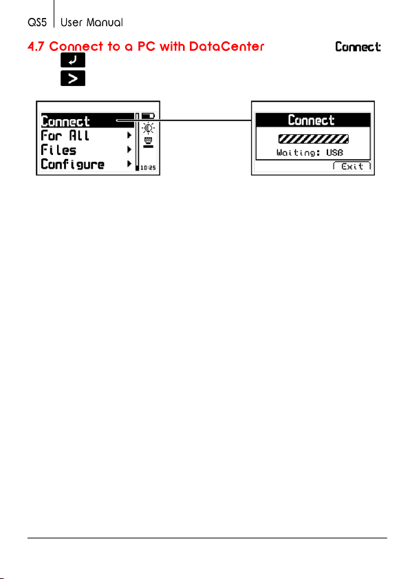
Touch on Connect to enter the “waiting to connect” mode.
Touch to exit and cancel the connection.
Figure 4.16: Connecting to a PC
With the unit in “waiting to connect” make sure that the USB or the
RS232 cable (depending on the type of connecting cable that you are
using) is properly connected to both the unit and the PC and click on
<Connect> in DataCenter.
When a successful connection is established the files in your unit
memory will appear in DataCenter. To view their contents simply
double click on each file.
For additional information on dmq DataCenter software refer to the
manual included in the CD that you received with your QS5 or
download the manual at http://www.demeq.com/Download.html
64 Chapter 4
Page 77
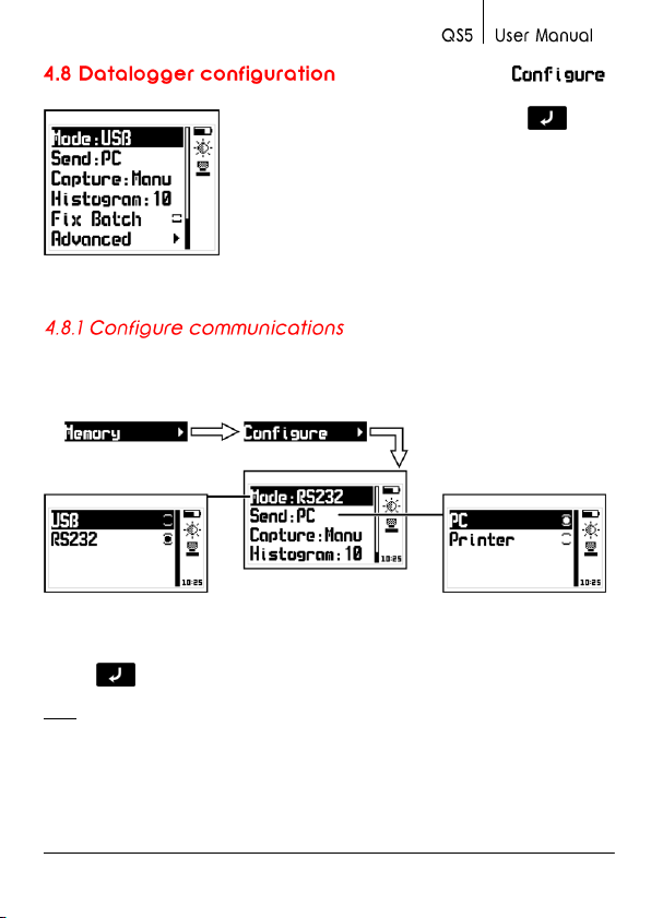
In the memory menu touch on
Configure to open the Datalogger
configuration options menu.
Figure 4.17: Datalogger configuration options menu
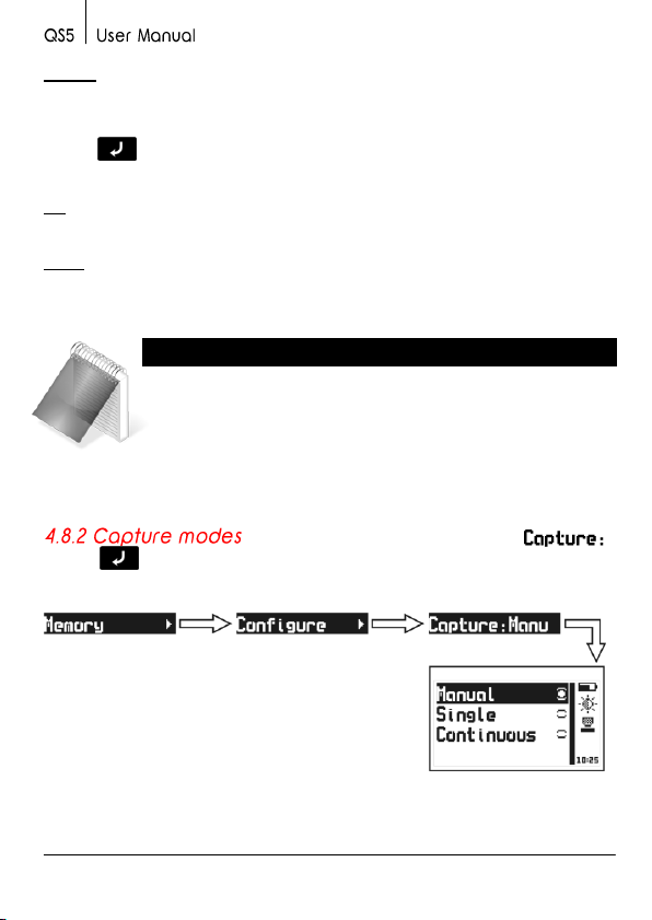
The first two options in the configure Datalogger menu are Mode and
Send which allow you to select how the unit will communicate with a
PC or a printer.
Figure 4.18: Configure communications options
Touch on Mode to select the type of connection.
USB: Select USB to connect to a PC using a USB cable (included). You
must already have DataCenter installed in your PC.
Chapter 4 65
Page 78
Notes
The print option can only be used with RS232 printers.
Files cannot be sent directly to a USB printer.
When you use DataCenter to connect, your selection of
PC or Print will not affect communication.
RS232: Select RS232 to connect to a PC or a printer using an RS232
cable (optional).
Touch on Send to select whether you will send files to a PC or a
printer.
PC: When using an RS232 cable, the unit sends data in an optimal
format for Windows HyperTerminal (38400-8-N-1).
Print: Using an RS232 cable and printer, the unit sends data in an
optimal format for mini-printers of 40 columns (9600/8-N-1).
Touch on Capture to select the mode in which values will be
stored in the Datalogger.
66 Chapter 4
Figure 4.19: Memory capture modes menu
Page 79
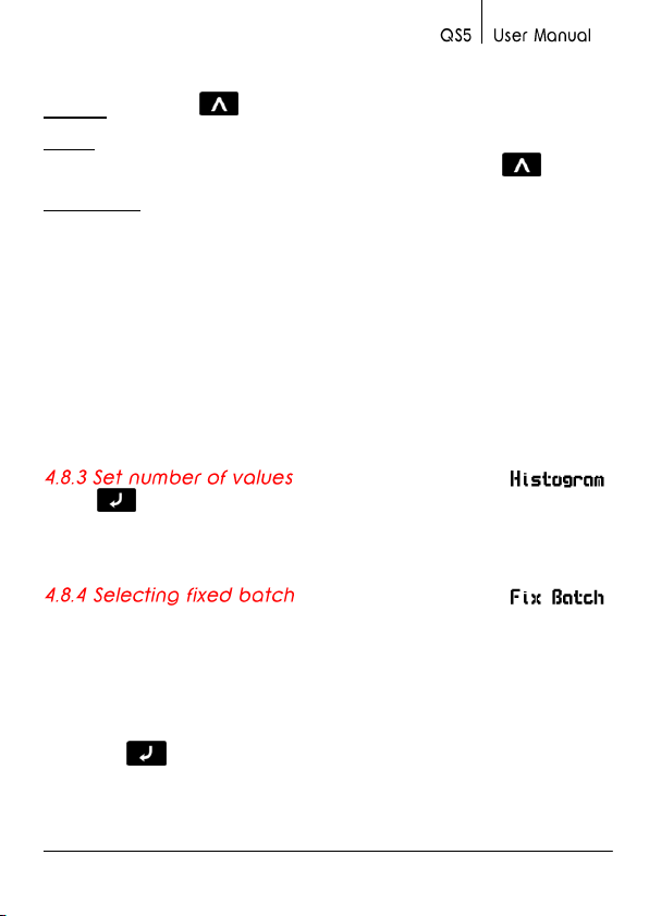
The QS5 has the following capture modes:
Manual: Touch the key to store values.
Single: Each time the transducer is coupled a thickness measurement
is stored. In this mode values can also be stored using the key.
Continuous: When the transducer is coupled thickness measurements
are continuously stored at a rate of:
Refresh / N
Where refresh refers to the number of values per second that the unit
reads (Page 45) and N refers to the Store Every (N number of values)
that can be set on the Advanced Datalogger menu options (Page 67).
Touch on Histogram to set the number of values for each batch
when the Fix Batch option is enabled.
When the Fix Batch option is enabled the unit automatically closes a
batch and opens a new one when the number of values that you set
for the histogram is reached. When the Fix Batch option is disabled
values are stored until the batch is manually closed. You can close a
batch by entering the “Batch” option by touching the “Mem” key
while you are in the measuring screen.
Touch the key to enable or to disable the Fix Batch option.
Chapter 4 67
Page 80
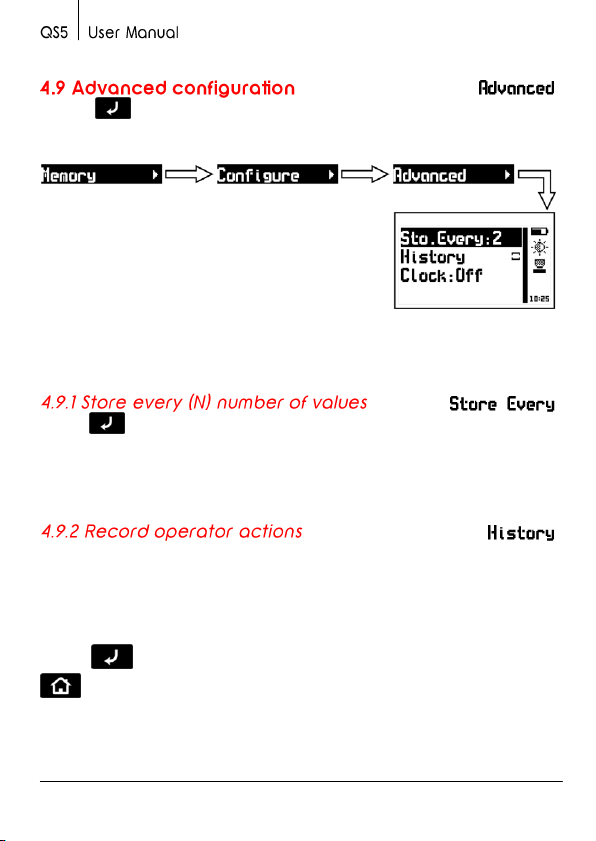
Touch on Advanced to access the advanced configuration
options menu for the Datalogger.
Figure 4.20: Advanced Datalogger configuration options menu
Touch on Store Every to set the number of measurements done
by the unit before a value (measurement) is actually stored in the
Datalogger when Continuous capture mode is enabled (Page 66).
When you enable history the Datalogger will register the unit settings
for each measurement that is stored. Information such as gain, trigger,
velocity and calibration settings are stored along with the thickness
value. This data can only be viewed in DataCenter. When history is
enabled the unit memory capacity decreases as more data is stored.
Touch on History to enable or disable this option and touch
to exit.
68 Chapter 4
Page 81
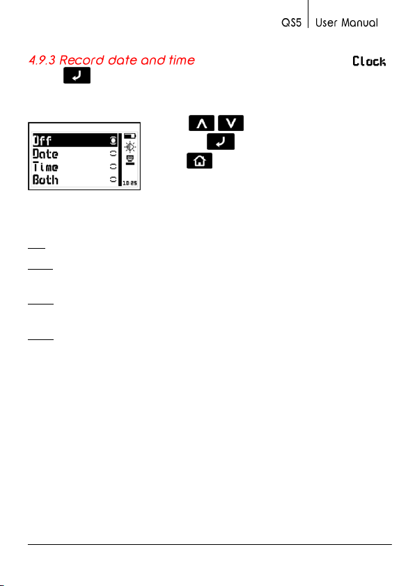
Touch on Clock to set the time and date options that will be
recorded by the Datalogger each time a new batch is opened.
Touch - to scroll all menu options
and touch to select and exit.
Touch to exit without making changes.
Figure 4.21: Record date and time in the Datalogger
Off: The Datalogger does not record date and time.
Date: Each time a new batch is opened the Datalogger records the
date.
Time: Each time a new batch is opened the Datalogger records the
time.
Both: Each time a new batch is opened the Datalogger records the
date and time.
Chapter 4 69
Page 82

Do not measure outside the thickness range specified for the
transducer that you are using.
Use just enough coupling gel to ensure stable measurements. Avoid
using excessive coupling gel as it may be added to the thickness value
of the actual test piece being measured.
Always do the zero calibration using the calibration disk located in the
front of the unit particularly when changing transducers.
Have a reference test piece of the same material that you will be
measuring and know the velocity of the material or its thickness value
so that you can precisely determine the velocity of the material based
on its thickness.
Gain and trigger levels are set from factory with the optimal values
that correspond to the transducer that was shipped with your unit.
When a transducer is changed gain and trigger levels should be
adjusted to optimize transducer functionality.
Appendix
Page 83
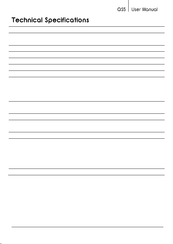
Measuring principal
Pulse-Echo / Echo-Echo
Measuring range
0.6 mm to 500 mm (Pulse-Echo)
2.5 mm a 20 mm (Echo-Echo)
Transducer frequency
2 to 10 MHz
Capture speeds
4, 8 and 20 Hz
Pulser tension
Adjustable 20 V to 210 V
V-Path
Automatic correction
Units
Millimeters, Inches and Microseconds
Resolution
0.01 mm from 0.60 to 99.99 mm
0.1 mm from 100.0 mm and above
0.001 in from 0.040 to 9.999
0.01 in from 10.00 in and above
Material velocity
100 to 19999 m/S
3.937 to 787.3 in/ms
Calibration
Auto, 1-Point and 2-Point
Alarms
Defects, Min., Max.
Audible and visual
Languages
English, Spanish, Portuguese
Datalogger
Capacity of 32000 values organized in up to
8 files with alphanumeric names.
Manual, Single, Continuous capture modes.
Record Date and Time. View data including
statistics in grid or graphic formats.
Connection to PC
USB native or RS232 (optional)
Appendix
Page 84

Display
Graphic LCD 128 x 64 pixels with LED
backlight illumination and contrast
adjustment.
Keypad
Touch-sense with no mechanical parts and
sensitivity adjustment.
Battery life
100 hours with 2 each type AA batteries
Operating temp.
- 10°C to + 50°C
Enclosure
High impact ABS with rubber sides. Size is
78 x 117 x 24 mm.
Weight
200 g with batteries
Appendix
Page 85
The QS5 was developed and manufactured for years of trouble free
operation and even though the unit does not require special care the
following precautions should be considered:
Avoid contact with corrosive and abrasive substances.
Do not clean the unit with solvents.
Do not leave the unit display exposed to direct solar light for
prolonged periods of time as this could damage the display.
Remove the batteries if the unit will be stored for an
extended period of time.
Remove the transducer using the connectors and not the
cable.
Do not twist or strangle the transducer cables.
Do not expose the unit to temperatures below -10°C / 14°F or
above 50°C / 122°F.
Appendix
Page 86
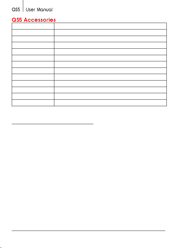
dmq part No.
Description
QSM 300
Small high impact carrying case
QSS 201
2Mhz transducer – 15 mm diameter
QSS 501
5Mhz standard transducer – 10 mm diameter
QS5 501 HD
5MHz Hi-Damp transducer – Thru-Paint
QSS 701
7Mhz transducer – 5 mm diameter
QSR 161
6 step calibration block (mm)
QSR 141
4 step calibration block (in)
QSG 001
Coupling gel
QSL 102
QS5 B to QS5 DL upgrade license
QSL 301
QS5 E to QS5 DLE upgrade license
QAC 002
RS232 cable to connect to a PC
QAC 003
RS232 cable to connect to a printer
For additional information and accessories for your QS5 visit
www.demeq.com/Accessories-QS.html
Appendix
Page 87
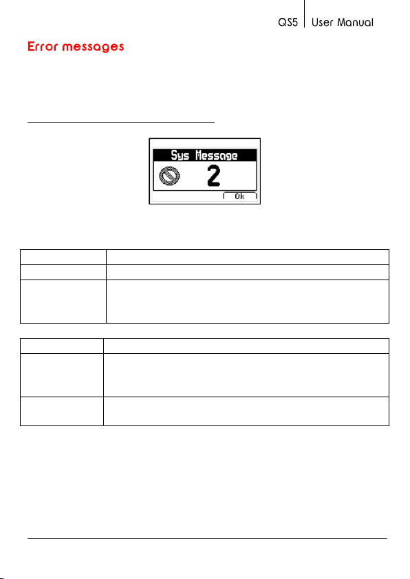
Error 1
Internal Error
Cause
Internal Error
Solutions
Shutdown the unit, wait a few seconds, and power
back on.
Contact dmq.
Error 2
Attempt to store a value over an existing value.
Cause
Improper unit shutdown (Example: Removing
batteries) and powering the unit back on to store
values in the Datalogger.
Solution
Download Datalogger values to PC or printer and
erase memory.
Error messages may eventually open on your unit screen and are
informational only. If one of these messages opens on your display
follow the instructions described below and if the problem persists
please send us a detailed report at
www.demeq.com/form_Support.html
Figure A.2: System error message
If a message with a different number appears on your unit display
please contact dmq immediately.
Appendix
Page 88
Our website is a powerful customer support tool where you will find
the latest information as it relates to your QS5 including:
Application notes
Manuals and brochures
Software updates
Model upgrade license information
New accessories
To download software updates to your QS5 you must have dmq
DataCenter installed on your PC. To download the latest updates for
your unit refer to www.demeq.com/Download.html
Our service department is committed to providing prompt and
courteous service. Should you encounter any trouble with your QS5
please send us a detailed description of your problem to
www.demeq.com/form_Support.html
Appendix
Page 89
P/N QSD-501-ENG-Rev 3 ©2012 dmq
77 Capitulo 4
 Loading...