

Page 1
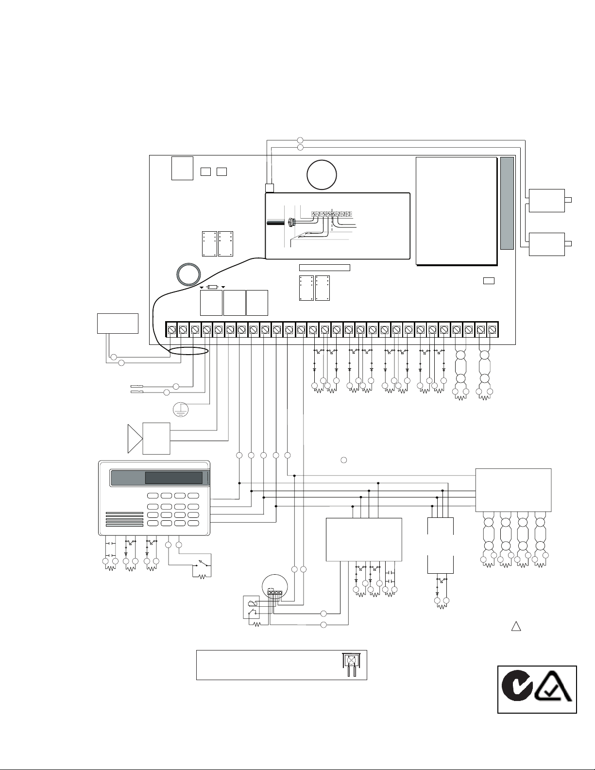
MODEL XR200A WIRING DIAGRAM
Refer to the XR200A Installation Guide (LT-0482) for a complete description of wiring connections.
Refer to the XR200 Programming Manual (LT-0196) for complete programming instructions.
Primary Power
16VAC
40 - 100 VA
Secondary Power Supply
1.2 Amps max. charging current.
Use only 12 VDC rechargable
batteries. DMP Model 367.
Replace every 3 to 5 years.
Bell
12 VDC nominal
Total current 1.5 Amps max.
Keypads
Model 670, 770, and 771
125mA at 8 to 16 VDC.
Model 690
90mA at 8 to 16 VDC.
Model 790 and 791
100mA at 8 to 16 VDC.
Model 793
130 mA at 8 to 16 VDC.
s s s s s s
Keyswitch Arming
Can be connected to any loop.
Refer to LT-0164 for a list of approved 4-wire
smoke detectors and power supervision relays.
Phone Jack Connector
16 to 18 gauge wire
s
s
Maximum AC wire distance
With 16 gauge wire: 70 feet
With 18 guage wire: 40 feet
Protective
Earth Ground
Bell
1k Ω
1k Ω 1k Ω
Danger of explosion if lithium battery is incorrectly replaced.
CAUTION
Replace only with DMP part number BT-0005 or equivalent
type. When discharged, disposal of used lithium battery is
non- hazardous per USEPA criteria. Disposal according to
local, state, and federal waste regulations.
s
s
DD, MPX
Selection
J3
Answering
Machine
Bypass Relay
Use Model 305
AC
AC +B -B BELL GND SMK GNDRED YEL GRN BLK Z1 Z2GND GND GND GNDZ3 Z4 Z5 Z6 Z7 Z8 Z9 + Z9 - Z10 + Z10 -
1 2 3 4 5 6 7 8 10 11 12 13 14 15 16 17 18 1
s
s
RED
Ground Start Relay
Use Model 305
K2
BLACK
J11J12
Tamper Header
K4
Output Header J2
Battery Only Restart CR7
RED
22 GA. MIN
s s s s s
Lithium
J4
AC wiring must be in conduit and exit out the left
side of the enclosure.
Relay Output 1
Use Model 305
9 20 21 22 23 24 25 26 27 28
YELLOW
BLACK
GREEN
22 GA. MIN
22 GA. MIN
22 GA. MIN
Battery
J2
K7K6
Relay Output 2
Use Model 305
ZONE 2
ZONE 1
ssss
s
1k Ω
1k Ω
1k Ω 1k Ω 1k Ω 1k Ω 1k Ω 1k Ω
Auxiliary Power
Total current 1.0 Amps
combined from Terminals
7, 11, 26, & 28.
s
= Supervised Circuit
Red
Red
Yellow
Green
Black
Wiring on terminals
5 through 22 must
exit to the right and
maintain a 1/4"
separation from the
AC and battery
positive wiring.
9
ZONE 4
ZONE 3
ZONE EXPANDER
Model 714
s s
DISARM
ARM
1k Ω
Power
Supervision
Relay
Smoke
Detector
Ð
s s
+
15mAat 12 VDC
Models 714-8, 714-16
20mA @ 12 VDC
s
1k Ω 1k Ω 1k Ω
s
1k Ω
DMP Model 310
In all applications where more than one wire is
under a terminal, the wire must be cut and not
looped around the screw terminal.
s
Form C Relays
Output 1 N/C Violet
Output 1 Com Gray
Output 1 N/O Orange
Output 2 N/C Violet
Output 2 Com Gray
Output 2 N/O Orange
Voltage Outputs
Output 3 White/Orange
Output 4 White/Yellow
Output 5 White/Green
Output 6 White/Blue
Output 7 White/Violet
Output 8 White/Gray
Output 9 White
Output 10 White/Black
Ground Black
J2 Output color code for
Model 430 Output Harness
ZONE 6
ZONE 5
ssss
ZONE 7
EXPANDER
Model 711/711E
sssss
ZONE 8
s
ssssss
ZONE
12mA at
12 VDC
s s
1k Ω
ZONE 9
3.3k Ω
DMP Model 309
Front Tamper
Rear Tamper
J6 Interface Connector
J6
Tamper protection
when required for
Model 350A Attack
Resistant Enclosure.
Heat detectors,
pull stations, or
any other shorting
devices can be
connected to
zones 9 and 10.
Zones 9 and 10 and
Model 715 compatibility
identifier: A
Maximum operating
range:
8.8 VDC to 14.2 VDC.
Resistor
J16
Command
Processor
Reset
ZONE 10
ssss
Resistor
3.3k Ω
DMP Model 309
ZONE EXPANDER
Model 715
25mA @ 12 VDC
Models 715-8, 715-16
20mA @ 12 VDC
sssssss
3.3k Ω 3.3k Ω 3.3k Ω 3.3k Ω
See the XR200A Installation Guide for a
list of approved 2-wire smoke detectors
for zones 9 and 10 and 715 Zone
Expanders.
WARNING!
Installation to be
performed by
authorized personnel.
s
!
Downloaded from: http://www.guardianalarms.net
ACN 087 480 279
LT-0468 (12/99)
 Loading...