

Page 1
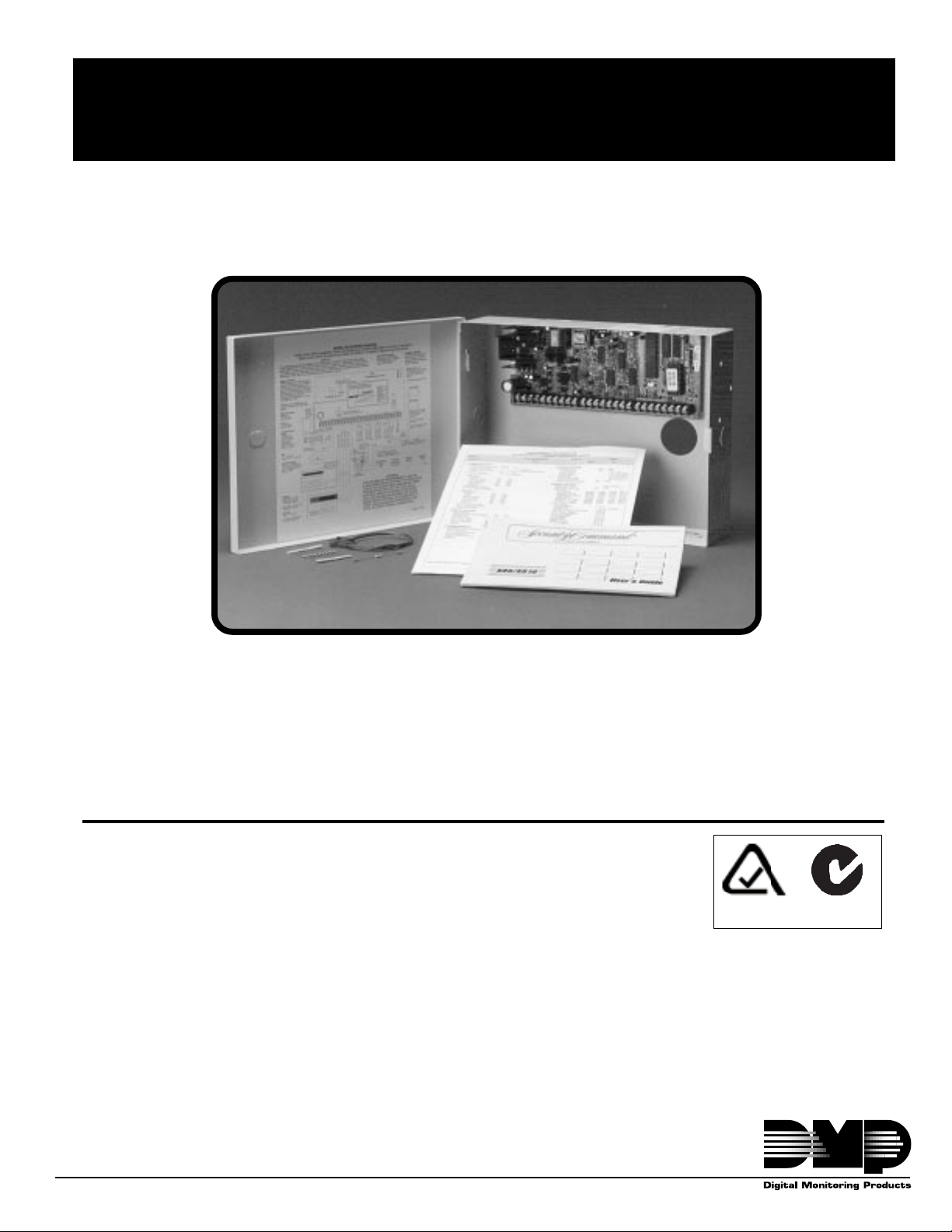
XR6A/XR10A/XR20A Command Processor
Installation Guide
TM
Panels
6/10/26 Zone Burglary/Fire/Access Control Panels with Built-in Communicator
ACN 087 480 279
2841 E. Industrial Drive Springfield, MO USA 65802-6310
Downloaded from: http://www.guardianalarms.net
LT-0464 (6/99)
Page 2

MODEL XR6A/XR10A/XR20A
COMMAND PROCESSOR
TM
INSTALLATION GUIDE
COMPLIANCE STATEMENT
The DMP Model XR6A, XR10A, and XR20A systems have been tested and comply with the requirements of CISPR22
Class B Electromagnetic Emissions, ACA Technical Standard TS001-1997 Electrical Safety, AS/NZS 3260-1993
including amendments 1 to 4 Electrical Safety, and ACA Technical Standard TS002-1997 Telecommunications.
ACN 087 480 279
Copyright © 1995 - 1999 Digital Monitoring Products, Inc.
Information furnished by DMP is believed to be accurate and reliable.
This information is subject to change without notice.
Page 3

TABLE OF CONTENTS
Section Page
Panel Specifications ........................................................................................... 5
1.1 Po wer supply....................................................................................................5
1.2 Communication ................................................................................................5
1.3 Panel zones......................................................................................................5
1.4 Keypads ...........................................................................................................5
1.5 Outputs.............................................................................................................5
1.6 Enclosure specifications ...................................................................................5
Introduction ......................................................................................................... 6
2.1 Description .......................................................................................................6
2.2 System configurations ......................................................................................6
2.3 Before you begin ..............................................................................................6
2.4 About this guide................................................................................................6
2.5 How to use this guide .......................................................................................6
System Components .......................................................................................... 7
3.1 Description .......................................................................................................7
3.2 Wiring diagram .................................................................................................7
3.3 Lightning protection ..........................................................................................7
3.4 Command Processor Accessories ...................................................................7
Installation ........................................................................................................... 9
4.1 Mounting the enclosure ....................................................................................9
4.2 Mounting keypads ..........................................................................................10
4.3 Wiring keypads...............................................................................................10
Primary Power Supply ...................................................................................... 10
5.1 AC terminals 1 and 2 ......................................................................................10
5.2 T ransf ormer types...........................................................................................10
Secondary Power Supply ................................................................................. 11
6.1 Battery terminals 3 and 4 ...............................................................................11
6.2 Earth ground ..................................................................................................11
6.3 Replacement period .......................................................................................11
6.4 Discharge/recharge ........................................................................................11
6.5 Battery supervision.........................................................................................11
6.6 XR6A/XR10A/XR20A power requirements .....................................................11
Bell Output......................................................................................................... 13
7.1 Terminals 5 and 6 ...........................................................................................13
Keypad Data Bus............................................................................................... 13
8.1 Description .....................................................................................................13
8.2 Terminal 7 - RED ............................................................................................13
8.3 Terminal 8 - YELLO W .....................................................................................13
8.4 Terminal 9 - GREEN .......................................................................................13
8.5 Terminal 10 - BLACK ......................................................................................13
Smoke and Glassbreak Detector Output ........................................................ 13
9.1 T erminal 11.....................................................................................................13
Burglary Zones.................................................................................................. 14
10.1 Description .....................................................................................................14
10.2 Operational parameters..................................................................................14
10.3 Zone response time........................................................................................14
10.4 Keys witch arming zone...................................................................................14
Page 4

TABLE OF CONTENTS
Section Page
Powered Zone for 2-Wire Smoke Detectors.................................................... 15
11.1 Terminals 25 and 26 .......................................................................................15
Annunciator Outputs ........................................................................................ 16
12.1 Description .....................................................................................................16
12.2 Harness wiring ...............................................................................................16
Telephone RJ Connector .................................................................................. 16
13.1 Description .....................................................................................................16
13.2 ACA Compliance ............................................................................................16
13.3 Ground start ...................................................................................................16
Reset Jumpers J16 ........................................................................................... 17
14.1 Description .....................................................................................................17
Troubleshooting Section .................................................................................. 17
15.1 Description .....................................................................................................17
Page 5

Panel Specifications
1.1 Power supply
Transformer Input: 16.5 VAC 40VA or 16.5 VAC 20VA
Standby Battery: 12 VDC 7.0Ah (40VA transformer charges up to 2 batteries)
Auxiliary Output: 12 VDC at 500mA
Bell Output: 12 VDC at 1.5 Amps with 40VA transformer, 600mA with 20VA transformer
Smoke Detector Output: 12 VDC at 100mA
All circuits inherent power limited
1.2 Communication
Built-in SDLC Digital Dialer communication to DMP Model SCS-1 Receivers
Built-in 4-2 communication to non-DMP receivers
Built-in M2E (Radionics Modem IIe) communication to non-DMP receivers (XR20A only)
Built-in CID (Contact ID) communication to non-DMP receivers
All panels can operate as a local system.
1.3 Panel zones
Nine 1k W EOL burglary zones (zones 1 to 9), (zones 1 to 5 on XR6A)
One 3.3k W EOL Class B powered fire zone with reset capability (zone 10 on XR10A and XR20A), (zone 6 on
XR6A)
Introduction
1.4 Keypads
You can connect up to four of the following supervised keypads to the XR6A/XR10A/XR20A panels.
• 16 or 32 character alphanumeric keypads
• 10-zone LED keypads
In addition, four and single point zone expanders can be added to the XR20A panel.
When using the FA426 Wireless Receiver, the XR20A allows unsupervised devices to be added to address five.
1.5 Outputs
The XR6A/XR10A/XR20A panels provide four open collector outputs rated for 50mA each. See section 12.1. A
Model 300 Wire Harness is required. The open collector outputs provide the ground connection for a positive
voltage source.
1.6 Enclosure specifications
The XR6A/XR10A/XR20A panel ships in an enclosure with EOL resistors, battery leads, user's guide, and
programming sheet.
Size: 12.5" W x 9.5" H x 2.75" D
Weight: 4 lbs
Color: Gray or Black
Construction: 20 gauge cold rolled steel
XR6A/XR10A/XR20A Installation Guide
2841 E. Industrial Drive Springfield, MO USA 65802-6310 800-641-4282 Digital Monitoring Products
Page 1
Page 6

Introduction
Introduction
2.1 Description
The DMP XR6A/XR10A/XR20A Command Processors are powerful 12 VDC burglary and fire communicator
panels with battery backup. The XR10A/XR20A provide nine on-board burglary zones and one on-board 12 VDC
Class B powered fire zone. The XR6A provides five burglary and one fire zone. The fire zone has a reset
capability to provide for 2-wire smoke detectors, relays, or other latching devices. The XR6A/XR10A/XR20A can
communicate to one or two DMP SCS-1 Receivers using SDLC digital dialer, 4-2, or Contact ID (CID) reporting
formats. In addition, the XR20A can communicate using the Radionics Modem IIe format.
2.2 System configurations
The XR6A/XR10A/XR20A can be programmed to operate as either an All/Perimeter system that provides one
Perimeter area and one Interior area, or as a Home/Sleep/Away system that provides one Perimeter, one Interior,
and one Bedroom area. The Bedroom area can include any protection devices the user wants disarmed during
their sleeping hours and armed in the Away mode. In addition, the XR20A can operate as a four area system.
2.3 Before you begin
Before installing the XR6A/XR10A/XR20A, we recommend you read through the entire contents of this guide.
Familiarize yourself with the features of the panel and the key points to remember during the installation. Be sure
to read and understand all of the caution statements printed in bold italics.
In addition to this installation guide, you should also read through and familiarize yourself with these other product
documents:
• XR6/XR10 Programming Guide (LT-0230) • XR20 Programming Guide (LT-0305)
• XR6/XR10 Program Information Sheet (LT-0212) • XR20 Program Information Sheet (LT-0302)
• XR6/XR10 Security Command User's Guide (LT-0226) • XR20 Security Command User's Guide (LT-0303)
2.4 About this guide
The information contained in this guide is organized into three sections: Table of Contents, Introduction, and
Installation.
• The Table of Contents at the front of this guide lists all of the headings and subheadings used throughout
each section and the page number where the information can be found.
• The Introduction section gives you an overview of the various components that go into a XR6A/XR10A/
XR20A system and diagrams some typical system configurations. This section gives descriptions of the
panel, keypads, and accessory modules and provides details on how each of them operate together in the
system.
• The Installation section begins with mounting instructions for the enclosure and takes you through the
proper way to power up the panel prior to programming.
Caution notes
Throughout this guide you'll see caution notes containing information you need to know when installing the
XR6A/XR10A/XR20A panel. These cautions are written with a bold, italicized introductory clause followed by a
detailed description of the caution. See the example shown below:
Always ground the panel before applying power to any devices:
grounded before connecting any devices or applying power to the panel. Proper grounding protects against
Electrostatic Discharge (ESD) that can damage system components.
Whenever you see a caution note, make sure you completely read and understand its information. Failing to
follow the caution note can cause damage to the equipment or improper operation of one or more components in
the system.
The XR6A/XR10A/XR20A must be properly
2.5 How to use this guide
To locate information about the installation of the XR6A/XR10A/XR20A, first go to the Table of Contents at the
front of this guide. Find the subject heading that closely describes the information you need and turn to the
section number shown to the right of the heading.
The text that follows the heading has been written to provide as much information about the subject as possible. If
you can't find the information you need under that heading, try scanning through a few of the headings before and
after and reading the text under those that sound similar.
XR6A/XR10A/XR20A Installation Guide
Digital Monitoring Products 2841 E. Industrial Drive Springfield, MO USA 65802-6310 800-641-4282
Page 2
Page 7

Introduction
System Components
3.1 Description
The DMP XR6A/XR10A/XR20A system is made up of an alarm panel with built in communicator, an enclosure, a
16.5 VAC transformer, and a 12 VDC 7.0 Ah battery. You can add up to four Security Command keypads to the
system and can also connect auxiliary devices to the panel's open collector outputs to expand the basic system.
Combined current requirements of additional modules may require an auxiliary power supply. Refer to section 6.6 in
this guide when calculating power requirements. In addition, up to 16 points of zone expansion can be added to the
XR20A and four points to the XR6A.
3.2 Wiring diagram
The XR6A/XR10A/XR20A system wiring diagram in Figure 1 shows some of the accessory devices you can
connect for use in various applications. A complete description of each module follows. Zone expanders can be
added to the XR6A or XR20A.
3.3 Lightning protection
Metal Oxide Varistors and Transient Voltage Suppressors help protect against voltage surges on input and output
circuits. A transorb is provided for the Smoke Detector Output Circuit (Terminal 11). This transient protection
provides additional resistance to electrical surges such as lighting. Additional surge protection is available by
installing the DMP 370 or 370RJ Lightning Suppressors.
3.4 Command Processor Accessories
You can connect any combination of up to four Model 670, 770, and 771 vacuum fluorescent, 690, 790, 791, and
793 LCD, or 692 LED Security Command Keypads to the 4-wire keypad data bus provided by the panel on
terminals 7, 8, 9, and 10. Also, you can connect Model 714, 715, 714-8, 714-16, 715-8, 715-16 zone expanders
to the XR20A or XR6A 4-wire keypad bus. (Note: The XR10A does not support zone expansion on the keypad
bus.)
XR6A/XR10A/XR20A Installation Guide
2841 E. Industrial Drive Springfield, MO USA 65802-6310 800-641-4282 Digital Monitoring Products
Page 3
Page 8

Introduction
Tamper protection wh
required for M od el 3 49Attack Resistant
Enclosure.
Zone 10 compatibility
identifier: A
Maximum operating
Front Tamper
Output He ad er J11
Use DMP Model 300 Harnes
123
4
J11
Rear Tamper
et
Sock
U11
EPROM
range: 8.8 VDC - 14.2VDC.
2-wire
smoke
detector
ZONE 10
ZONE 9
ZONE 8
1K 1K 1K 1K 1K
1K
ACN 087 480 279
LT-0449 (5/99)
ZONE 7
ZONE 6
6
E
ZON
J16
1K 1K 1K
ZONE 5
ZONE 4
Heat detectors, manual pull stations, or
any other shorting device. Unlimited
number of units.
ZONE 3
Command Processor Reset
For XR6A terminal block zone wiring
5
E
ZON
4
3
2
1
For XR10A and XR20A terminal block zone wiring
E
ZON
E
ZON
E
ZON
E
ZON
ZONE 2
ZONE 1
Smoke Output
100mA @ 10.4 - 13.2 VDC Terminal 11
Red
BLACK
GREEN
YELLOW
RED
22 GA. MIN
22 GA. MIN
22 GA. MIN
22 GA. MIN
+ -
Smoke
Detector
3.3k DMP Model 309
Black
4-wire smoke detector
Power
Supervision
Relay
J4
BLACK
Phone Jack Connector
AC AC +B -B BELL GN D RED YEL GR N BLK SMK Z1 GN D Z2 Z3 GN D Z4 Z5 GND Z6 Z7 GN D Z8 Z9 Z10+ Z10-
RED
Up to 500mA auxiliary
current at 10.4 - 13.2
VDC from Terminal 7.
Bell
16 - 18 gauge wire
Maximum AC wire distance
With 16 gauge wire: 70 feet
XR6A
XR10A
XR20A
Refer to the Command
ProcessorT M Pa nel
Programming an d I ns tallation
Guides for a com plete
description of program m ing
instructions and wiring
WIRING DIAGRAM
connections.
Primary Power
16 VAC
20 or 40 VA
Secondary
With 18 gauge wire: 40 feet
Battery Pow er
1.2 Amps max.
charging current.
Use only 12 VDC
Cold Water Pipe
Earth Ground
rechargable batteries.
DMP M ode l 367.
Replace every
3 - 5 years.
Bell
10.4 - 13.2 VDC
Total current:
1.5 Amps max. w/ 40 VA
600mA w/ 20 VA
Keypads
Models 670. 770, 771,
100mA @ 8 - 16 VDC
125mA wi th dis p la y lit
Models 690, 790, 791,
793
100mA @ 8 - 16 VDC
Model 692
75mA @ 8 -16 VDC
Figure 1: XR6A/XR10A/XR20A wiring diagram
XR6A/XR10A/XR20A Installation Guide
Digital Monitoring Products 2841 E. Industrial Drive Springfield, MO USA 65802-6310 800-641-4282
Page 4
Page 9
Installation
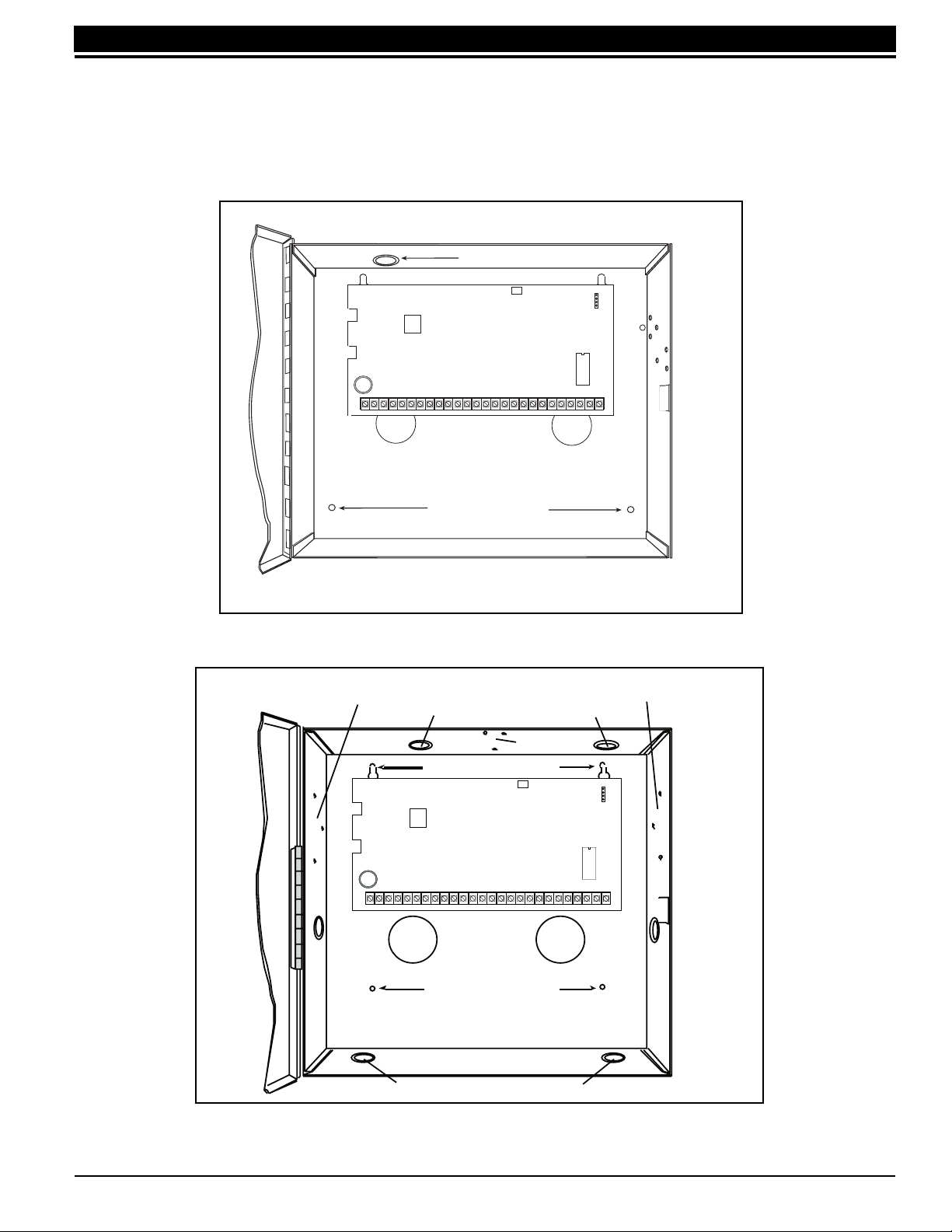
4.1 Mounting the enclosure
The metal enclosure must be mounted in a secure, dry place to protect the panel from damage due to tampering
or the elements. It is not necessary to remove the PC board when installing the enclosure.
Dual 1/2" and 3/4" Conduit Knockout
Installation
J11
1
2
3
4
U11
EPROM Socket
25
26
Z10+ Z10-
Z 7
GND
Z 8
Z 9
1
AC
234
AC +B -B
J4
Phone Jack Connector
56
RED
GND
BELL
78
9
YEL GRN BLK
10 11 12
SMK
13
Z1
GND
J16
Command Processor Reset
1516171819
14
Z3
Z2
GND
Z4 Z5 Z6
202122 23 24
GND
Enclosure Mounting Holes
Battery shelf
Figure 2: XR6A/XR10A/XR20A in standard enclosure
J11
U1 1
Accessory Module
Mounting Holes
1
2
3
4
Accessory Module
Mounting Holes
Dual 1/2" and 3/4" Conduit Knockouts
Enclosure Mounting Holes
Reset Jumper
J4
Phone Jack Connector
Tamper Switch
Mounting Holes
J16
EPROM Socket
12345678 10111213141516171819
AC
AC +B -B BELL GND SMK
9
RED YEL GRN BLK
Z1 Z2GND GND GND GNDZ3 Z4 Z5 Z6 Z 7 Z 8 Z 9 Z10+Z10-
20 21 22 23 24 25 26
Enclosure Mounting Holes
Battery Shelf
Dual 1/2" and 3/4" Conduit Knockouts
Figure 2A: XR6A/XR10A/XR20A in optional 349 Enclosure
XR6A/XR10A/XR20A Installation Guide
2841 E. Industrial Drive Springfield, MO USA 65802-6310 800-641-4282 Digital Monitoring Products
Page 5
Page 10

Installation
4.2 Mounting keypads
Security Command keypads have removable covers that allow you to easily mount the base to a wall or other flat
surface using the screw holes provided on each corner.
For mounting keypads on solid walls, or for applications where conduit is required, use a DMP 695, 696, 775, or
776 keypad conduit backbox.
4.3 Wiring keypads
Keypad data bus
The keypad data bus consists of a 4-wire cable that provides 12 VDC power, data in, data out, and a panel
common. You can connect keypads in parallel on one 4-wire cable or provide a separate cable run back to the
panel for each keypad. The maximum cable length for one keypad can be up to 500 feet using 22 gauge wire or
up to 1000 feet using 18 gauge wire. Additional keypads installed on the same cable decrease the maximum
distance at which they'll operate properly.
Refer to the 710 Bus Splitter/Repeater Module Installation Sheet (LT-0310) for additional information when
connecting keypads to a keypad bus circuit greater than 2,500 feet.
Primary Power Supply
5.1 AC terminals 1 and 2
Connect the transformer wires to terminals 1 and 2 on the panel. Use no more than 70 ft. of 16 gauge, or 40 ft. of
18 gauge, wire between the transformer and the XR6A/XR10A/XR20A.
Always ground the panel before applying power to any devices:
grounded before connecting any devices or applying power to the panel. Proper grounding protects against
Electrostatic Discharge (ESD) that can damage system components. See Earth ground, section 6.2.
The XR6A/XR10A/XR20A must be properly
5.2 Transformer types
The larger transformer for the XR6A/XR10A/XR20A is 16.5 VAC 40VA, which provides up to 1.5 Amps of bell
output current, 500mA of auxiliary current, and 100mA of smoke detector output. The total current available is
limited by the total battery standby requirements of the installation. When a 16.5 VAC 20VA plug-in transformer is
used, the bell output current is reduced to 600mA.
The transformer must be connected to a commercial power outlet that is not controlled by a wall switch. Never
share the transformer output with any other equipment.
XR6A/XR10A/XR20A Installation Guide
Digital Monitoring Products 2841 E. Industrial Drive Springfield, MO USA 65802-6310 800-641-4282
Page 6
Page 11

Installation
Secondary Power Supply
6.1 Battery terminals 3 and 4
Connect the black battery lead to terminal 4 on the panel and to the negative terminal of the battery. The negative
terminal connects to the enclosure ground internally through the XR6A/XR10A/XR20A circuit board. Connect the
red battery lead to terminal 3 on the panel and to the positive terminal of the battery. Observe polarity when
connecting the battery. The panel can charge up to two batteries.
Use sealed lead-acid batteries only:
battery. Batteries supplied by DMP or manufactured by Eagle Picher or Yuasa have been tested to ensure proper
charging with DMP products.
GEL CELL BATTERIES CANNOT BE USED WITH THE XR6A/XR10A/XR20A PANEL.
Use the DMP Model 367, 12 VDC 7.0Ah sealed lead-acid rechargeable
6.2 Earth ground
Terminal 4 of the XR6A/XR10A/XR20A panel must be connected to earth ground using 14 gauge or larger wire to
provide proper transient suppression. DMP recommends connecting to a metal cold water pipe or ground rod
only. Do not connect to electrical conduit or a telephone company ground.
6.3 Replacement period
DMP recommends the battery be replaced every 3 to 5 years under normal use.
6.4 Discharge/recharge
The XR6A/XR10A/XR20A battery charging circuit float charges at 13.9 VDC at a maximum current of 1.2 Amps
using a 40VA transformer. The total current available is reduced by the combined auxiliary current draw from
terminals 7, 11, and 25. The various battery voltage levels are listed below:
Battery Trouble: Below 11.9 VDC
Battery Restored: Above 12.6 VDC
6.5 Battery supervision
The XR6A/XR10A/XR20A tests the battery once every hour when AC power is present. The test lasts for five
seconds. A load is placed on the battery and if its voltage falls below 11.9 VDC a low battery is detected. If AC
power has failed, a low battery is detected any time the battery voltage falls below 11.9 VDC.
If a low battery is detected with AC power present, the test is repeated every two minutes until the battery
charges above 12.6 VDC; the battery restored voltage. If a faulty battery is replaced with a fully charged battery,
the restored battery will not be detected until the next two minute test is done.
6.6 XR6A/XR10A/XR20A power requirements
During AC power failure, the panel and all auxiliary devices connected draw their power from the battery. All
devices must be taken into consideration when calculating the battery standby capacity. On the following page is
a list of the power requirements of the XR6A/XR10A/XR20A panel. Add the additional current draw of Security
Command keypads, smoke detector output, and any other auxiliary devices used in the system for the total
current required. The total is then multiplied by the total number of standby hours required to arrive at the total
Ampere/hours required.
XR6A/XR10A/XR20A Installation Guide
2841 E. Industrial Drive Springfield, MO USA 65802-6310 800-641-4282 Digital Monitoring Products
Page 7
Page 12

Installation
XR6A/XR10A/XR20A STANDBY BATTERY POWER CALCULATIONS
Standby Current Alarm Current
Command Processor Panel 50mA ______ mA 50mA ______ mA
Active Zones 1-9 Qty _____ x 1.6mA ______ mA Qty _____ x *2mA ______ mA
Active Zone 10 (zone 6 on XR6A) 4mA ______ mA 30mA ______ mA
2-Wire Smoke Detectors Qty _____ x .1mA ______ mA Qty _____ x .1mA ______ mA
Bell Output 1500mA max. ______ mA
670, 770, and 771 Keypads Qty _____ x 125mA ______ mA Qty _____ x 125mA ______ mA
Annunciator (ON) Qty _____ x 20mA ______ mA
690, 790, 791, and 793 Keypads Qty _____ x 100mA ______ mA Qty _____ x 100mA ______ mA
Annunciator (ON) Qty _____ x 20mA ______ mA
692 Keypads Qty _____ x 30mA ______ mA Qty _____ x 30mA ______ mA
Annunciator (ON) Qty _____ x 10mA ______ mA
710 Bus Splitter/Repeater Qty _____ x 30mA ______ mA Qty _____ x 30mA ______ mA
711 or 714 Zone Expander Qty _____ x 7mA ______ mA Qty _____ x 7mA ______ mA
Active Zones (EOL installed) Qty _____ x 1.6mA ______ mA Qty _____ x *2mA ______ mA
715 Zone Expander Qty _____ x 7mA ______ mA Qty _____ x 7mA ______ mA
Active Zones (EOL installed) Qty _____ x 4mA ______ mA Qty _____ x 30mA ______ mA
2-Wire Smokes Qty _____ x .1mA ______ mA Qty _____ x .1mA ______ mA
714-8 or 714-16 Point Zone Expanders 20mA ______ mA 20mA ______ mA
Active Zones (EOL installed) Qty _____ x 1.6mA ______ mA Qty _____ x *2mA ______ mA
715-8 or 715-16 Point Zone Expanders 20mA ______ mA 20mA ______ mA
Active Zones (EOL installed) Qty _____ x 4mA ______ mA Qty _____ x 30mA ______ mA
2-Wire Smokes Qty _____ x .1mA ______ mA Qty _____ x .1mA ______ mA
733 Wiegand Interface 30mA ______ mA 30mA ______ mA
Active Zones (EOL installed) Qty _____ x 1.6mA ______ mA Qty _____ x *2mA ______ mA
Annunciator (ON) 20mA ______ mA
738A Ademco Wireless Interface 75mA ______ mA 75mA ______ mA
w/Receiver
FA426 16 Point Receiver 50mA ______ mA 50mA ______ mA
740/741/743 SC Keypads Qty _____ x 50mA ______ mA Qty _____ x 100mA ______ mA
Annunciator (ON) Qty _____ x 20mA ______ mA
Auxiliary Powered Devices on
Terminals 7 and 11 ______ mA ______ mA
(Other than keypads)
Total Standby ___________ mA Total Alarm ____________ mA
Total Standby ____________ mA x number of standby hours needed ______ = ___________ mA/hours
* Based on 10% of active
zones in alarm condition
Total Alarm + ___________ mA/hours
Total ___________ mA/hours
x_.001_____
= ___________ A/hours required
XR6A/XR10A/XR20A Installation Guide
Digital Monitoring Products 2841 E. Industrial Drive Springfield, MO USA 65802-6310 800-641-4282
Page 8
Page 13

Installation
Bell Output
7.1 Terminals 5 and 6
Nominal 12 VDC is supplied by terminal 5 on the panel to power alarm bells or horns. The output is rated for a
maximum of 1.5 Amps with a 40VA transformer and 600mA with a 20VA transformer. This output can be steady
or pulsed depending upon the Bell Action specified in Output Options programming. Terminal 6 is the ground
reference for the bell circuit.
Keypad Data Bus
8.1 Description
Terminals 7, 8, 9, and 10 of the XR6A/XR10A/XR20A panel are designated as the keypad data bus. In addition to
keypads, the XR20A allows the connection of any combination of zone expanders to the data bus up to a
maximum of four devices. The XR6A allows the connection of four zones on address one.
8.2 Terminal 7 - RED
Nominal 12 VDC is supplied at terminal 7 to power Security Command keypads and zone expanders. This is also
where power for any auxiliary device is supplied. The ground reference for terminal 7 is terminal 10. The
maximum output is rated at 500mA. All auxiliary devices totaled together must not exceed the panel's maximum
current rating of 500mA.
8.3 Terminal 8 - YELLOW
Data receive from keypads and zone expanders.
8.4 Terminal 9 - GREEN
Data transmit to keypads and zone expanders.
8.5 Terminal 10 - BLACK
Terminal 10 is the ground reference for Security Command keypads, zone expanders, and any auxiliary devices
being powered by terminals 7 and 11.
Smoke and Glassbreak Detector Output
9.1 Terminal 11
Nominal 12 VDC at 100mA maximum (shared by terminal 25) is supplied at terminal 11 to power 4-wire smoke
detectors or other auxiliary powered devices. This output can be turned off by the user for 5 seconds using the
Sensor Reset Menu Option. Terminal 10 is the ground reference for terminal 11.
XR6A/XR10A/XR20A Installation Guide
2841 E. Industrial Drive Springfield, MO USA 65802-6310 800-641-4282 Digital Monitoring Products
Page 9
Page 14

Installation
Burglary Zones
10.1 Description
The XR10A/XR20A terminals 12 to 24 are the nine burglary zones. For programming purposes, the zone
numbers are 1 to 9. The zone configurations on terminals 12 to 24 are described below. The XR6A terminals 12
to 18 are the five burglary zones with terminal 16 providing the ground for zone 5.
Terminal Function Terminal Function
12 Zone 1 voltage sensing 19 Ground for zones 5 & 6
13 Ground for zones 1 & 2 20 Zone 6 voltage sensing
14 Zone 2 voltage sensing 21 Zone 7 voltage sensing
15 Zone 3 voltage sensing 22 Ground for zones 7, 8, & 9
16 Ground for zones 3 & 4 (& 5 on XR6A) 23 Zone 8 voltage sensing
17 Zone 4 voltage sensing 24 Zone 9 voltage sensing
18 Zone 5 voltage sensing
The voltage sensing terminal measures the voltage flowing through the 1k W End Of Line resistor to the zone's
ground terminal. Dry contact sensing devices can be used in series (normally-closed) or in parallel (normallyopen) with any of the burglary protection zones.
10.2 Operational parameters
Each burglary protection zone detects three conditions: open, normal, and short.
The parameters for each are listed below:
Condition Resistance on zone Voltage on right terminal
Open over 1300 ohms over 2.0 VDC
Normal 600 to 1300 ohms 1.2 to 2.0 VDC
Short under 600 ohms under 1.2 VDC
1K
NORMALLY CLOSED CONTACTS NORMALLY OPEN CONTACTS COMBINATION: NORMALLY OPEN AND
1K
1K
NORMALLY CLOSED CONTACTS
Figure 3: Protection zone contact wiring
10.3 Zone response time
A condition must be present on a zone for 500 milliseconds before it's detected by the XR6A/XR10A/XR20A
panel. Ensure detection devices used on the protection zones are rated for use with this delay.
10.4 Keyswitch arming zone
Momentary keyswitches
You can use a momentary keyswitch on a zone programmed as an Arming type for use in arming and disarming
the system without a code.
XR6A/XR10A/XR20A Installation Guide
Digital Monitoring Products 2841 E. Industrial Drive Springfield, MO USA 65802-6310 800-641-4282
Page 10
Page 15

Installation
Powered Zone for 2-Wire Smoke Detectors
11.1 Terminals 25 and 26
A resettable 2-wire Class B powered zone is provided on terminals 25 (positive) and 26 (negative) of the panel.
For programming purposes, the zone number is 10 on the XR10A/XR20A and zone 6 on the XR6A. The zone
uses a Model 309, 3.3k W EOL resistor (provided with the panel) and has an operating range of 8.8 to 14.2 VDC.
Power is dropped from zone 10 any time a Sensor Reset is performed on the panel. Whenever non-Fire and nonSupervisory zone types are used on zone 10, make the appropriate adjustments to the zone's Armed Action to
prevent false alarms from occurring.
The UL compatibility identifier is: A.
rerutcafunaMledoM
smetsySnoitceteD282SDB enoNA/N0102/0161-517,8-517,517
smetsySnoitceteDHT282SDB enoNA/N0102/0161-517,8-517,517
smetsySnoitceteD052SDB W2BMA0102/0161-517,8-517,517
smetsySnoitceteDHT052SDB LW2BM/W2BMA0102/0161-517,8-517,517
smetsySnoitceteDDH052SDB LW2BM/W2BMA0102/0161-517,8-517,517
ikihcoH21-KLS4-DHN1-21-BSH,1-21-BSH08-BH0202/0161-517,8-517,517
ikihcoH/PMD538-KLS5-DHN002-BSH,002-BSH55-BH702/0161-517,8-517,517
ikihcoH/PMDH538-KLS5-DHN002-BSH,002-BSH55-BH702/0161-517,8-517,517
LSE/lortneSTA924A90SenoNA/N2102/0161-517,8-517,517
LSE/lortneSB125A90SenoNA/N2102/0161-517,8-517,517
LSE/lortneSTXB125A90SenoNA/N2102/0161-517,8-517,517
rosneSmetsyS0011DTSenoNA/N0102517
rosneSmetsyS1511DTSPL011BA/N0102517
rosneSmetsyS0041DTSenoNA/N0102/01517
rosneSmetsyS1541DTSB104B,104BA/N0102/01517
rosneSmetsyS0012DTSenoNA/N0102/01517
rosneSmetsyS0042DTSenoNA/N0102/01517
rosneSmetsyS1542DTS004HD,B104B,104BA/N0102/01517
rosneSmetsySHD1541DTS004HDA/N0102/01517
rosneSmetsyST0012DTSenoNA/N0102/01517
rosneSmetsySTA0042DTSenoNA/N0102/01517
rosneSmetsySTIA0042DTSenoNA/N0102/01517
rosneSmetsySHT0042DTSenoNA/N0102/01517
rosneSmetsySHT1542DTSB104B,104BA/N0102/01517
rotceteD
DIDIDIDIDI
esaBDIesaB
fo#
RX
srotceteDsrotceteD
srotceteDsrotceteD
srotceteD
lenaPlenaP
lenaPlenaP
lenaP
rednapxEenoZ
Figure 4: Compatible 2-wire smoke detectors
XR6A/XR10A/XR20A Installation Guide
2841 E. Industrial Drive Springfield, MO USA 65802-6310 800-641-4282 Digital Monitoring Products
Page 11
Page 16

Installation
Annunciator Outputs
12.1 Description
The four annunciator outputs can be programmed to indicate the activity of the panel's zones or conditions
occurring on the system. Annunciator outputs do not provide a voltage but instead switch to ground
voltage from another source. The outputs can respond to any of the conditions listed below:
1) Activation by zone condition: Steady, Pulse, Momentary, or Follower
2) Manually from the Security Command keypad
3) Communication failure
4) Armed area annunciation
5) Fire Alarm or Fire Trouble
7) Ambush alarm
8) Exit and Entry timers
9) System Ready
10) Ground start activation
12.2 Harness wiring
The open collector outputs are accessible by installing the DMP 300 Harness on the 4-pin header labeled J11.
The output locations are shown below:
Output Color Wire
1 Red 1
2 Yellow 2
3 Green 3
4 Black 4
Telephone RJ Connector
13.1 Description
Connect the panel to the public telephone network by installing a DMP 356 RJ Cable between the panel's J4
connector and the RJ31X or RJ38X phone jack.
Phone Cable Monitor
A two pin header labeled RJ SUP (J7) is provided to allow monitoring of the telephone cable connected between
the panel and a RJ38X jack (pins 2 & 7 jumpered). Attach a DMP Model 306 Harness between J7 and any
available zone. The pins of J7 are connected via the telephone cable to 2 & 7 of the RJ38X jack. The RJ38X jack
provides a jumper between pins 2 & 7 which completes the circuit.
When the zone is programmed for a Supervisory type (SV) and the telephone cable is removed, the keypad will
display the zone in trouble and produce a steady tone.
13.2 ACA Compliance
The XR6A/XR10A/XR20A have been tested and meet the requirements of ACA Technical Standard
TS-002-1997 for Telecommunications.
13.3 Ground start
To configure the XR6A/XR10A/XR20A for ground start operation, you must install the appropriate ground start
module and program one of the panel's available annunciator outputs for Ground Start operation. Refer to the
XR6A/XR10A/XR20A Programming Guide for complete programming information.
XR6A/XR10A/XR20A Installation Guide
Digital Monitoring Products 2841 E. Industrial Drive Springfield, MO USA 65802-6310 800-641-4282
Page 12
Page 17

Reset Jumpers J16
14.1 Description
There are two reset jumpers located at the top right of the panel's circuit board labeled RESET. Momentarily
shorting these jumpers allows you to reset the microprocessor of the XR6A/XR10A/XR20A. Resetting the panel
allows you to enter the panel's internal programmer.
To reset the panel when first installing the system, place the blade of a slotted screwdriver across the two reset
jumpers after applying power to the panel.
To reset the panel while the system is operational (for example, prior to reprogramming), you can short the
jumpers without powering down the system.
After resetting the panel for programming, you must begin within 30 minutes. If you wait longer than 30 minutes,
you'll have to reset the panel again.
Troubleshooting Section
15.1 Description
This section of the XR6A/XR10A/XR20A Installation Guide provides troubleshooting information for use when
installing or servicing an XR6A/XR10A/XR20A system.
Problem Possible Cause Solution
Installation
Security Command keypads
display " SERVICE REQUIRED"
Keypad display is not functional.
When a key is pressed, only a
short beep is emitted.
Keypad beeps when keys are
pressed but won't allow the user
to arm or enter the User Menu.
J16 reset jumper is installed.
Open or short on the green data
wire to the keypad.
Bad keypad or zone expander.
Open or short condition on the
yellow data wire.
Bad keypad or zone expander.
Two or more keypads are assigned
to the same address.
Remove the J16 reset jumper.
Check for broken or shorted wires
between the keypad and panel.
Replace with a new or repaired
keypad or zone expander.
Check for broken or shorted
wires.
Replace with a new or repaired
keypad or zone expander.
Set each keypad to a different
address to match the Device
Setup programming.
XR6A/XR10A/XR20A Installation Guide
2841 E. Industrial Drive Springfield, MO USA 65802-6310 800-641-4282 Digital Monitoring Products
Page 13
Page 18

Digital Monitoring Products
2841 E. Industrial Drive Springfield, MO 65802-6310 800-64104282
 Loading...