

Page 1
V-4404A 4-Channel Analog Converter
v i d e o
Description
The DMP V-4404A 4-Channel Analog Converter is a
useful security tool when connected to residential
and commercial security systems. Adding analog/
HD TVI cameras to the converter provides
businesses and homeowners with the ability to
visually check their premises at any time. It also
allows central station operators to have access to
live and recorded video when verifying an alarm.
Prior to use, it is necessary to activate the converter
and cameras by logging in to a dealer account at
dealeradmin.securecomwireless.com and entering the
serial number.
INSTALLATION GUIDE
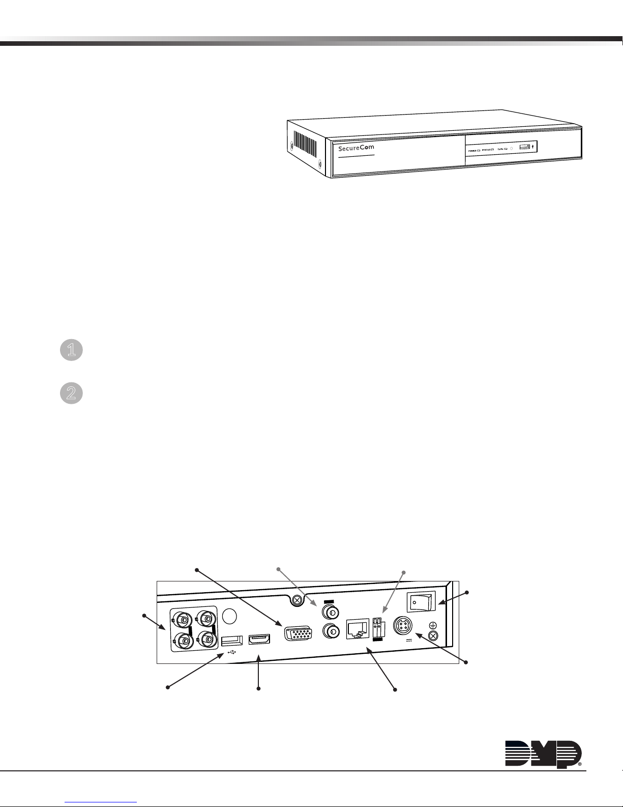
Figure 1: Front View - V-4404A 4-Channel
Analog Converter
Compatibility
• Analog cameras
• HD-TVI cameras
What is Included
• V-4404A 4-Channel Analog Converter
• 12V Power Transformer
Installing the 4-Channel Analog Converter
The 4-Channel Analog Converter is designed for convenient plug-and-play installation. It is possible to connect a
maximum of four cameras to the Converter.
Establish a Connection
1
Before installation of the Converter, establish a connection between the Converter and the Internet via the
LAN interface. Place the Converter in a location safe from liquid spills that is well ventilated and dust-free.
Add Analog Cameras
2
Each camera requires a dedicated cable from the camera to one of the four Video In BNC connectors on
the back panel of the Converter. The Video In connectors are numbered 1 through 4 and designate the four
channels that are available for the cameras.
For example: Camera 1 should be connected to BNC connector 1, Camera 2 should be connected to BNC
connector 2, etc.
Understanding the Back of the Converter
Below, is a short description of each connection on the back side of the V-4404A 4-Channel Converter.
VGA Interface
Connection to monitor for
viewing the camera output.
Video IN Connector
Connect up to four analog
cameras to the converter
using BNC connectors.
USB Port
Allows a USB mouse or
keyboard to connect to
the Converter.
Audio IN & Out Connectors
Audio In and Audio Out are not
available at this time.
2
1
3
VIDEO IN
VIDEO
OUT
4
Figure 2: Rear Panel
HDMI Interface
Plug one end of an HDMI
cable into a TV or monitor.
Connect the other end to the
Converter for camera viewing.
IN
VGAHDMI LAN
AUDIO
RS-485 Interface
RS-485 Interface is not
available at this time.
POWER
D+D-
12V
RS-485
LAN Network Interface
Plug one end of the included
network cable into the
Converter LAN port. Plug the
other end into the network
LAN/WAN connection.
Power Switch
For turning on or
off the Converter.
12V dc Power Supply
Attach the power supply
connector here and plug the
other end into an electrical
outlet that is not controlled
by a wall switch.
Page 2
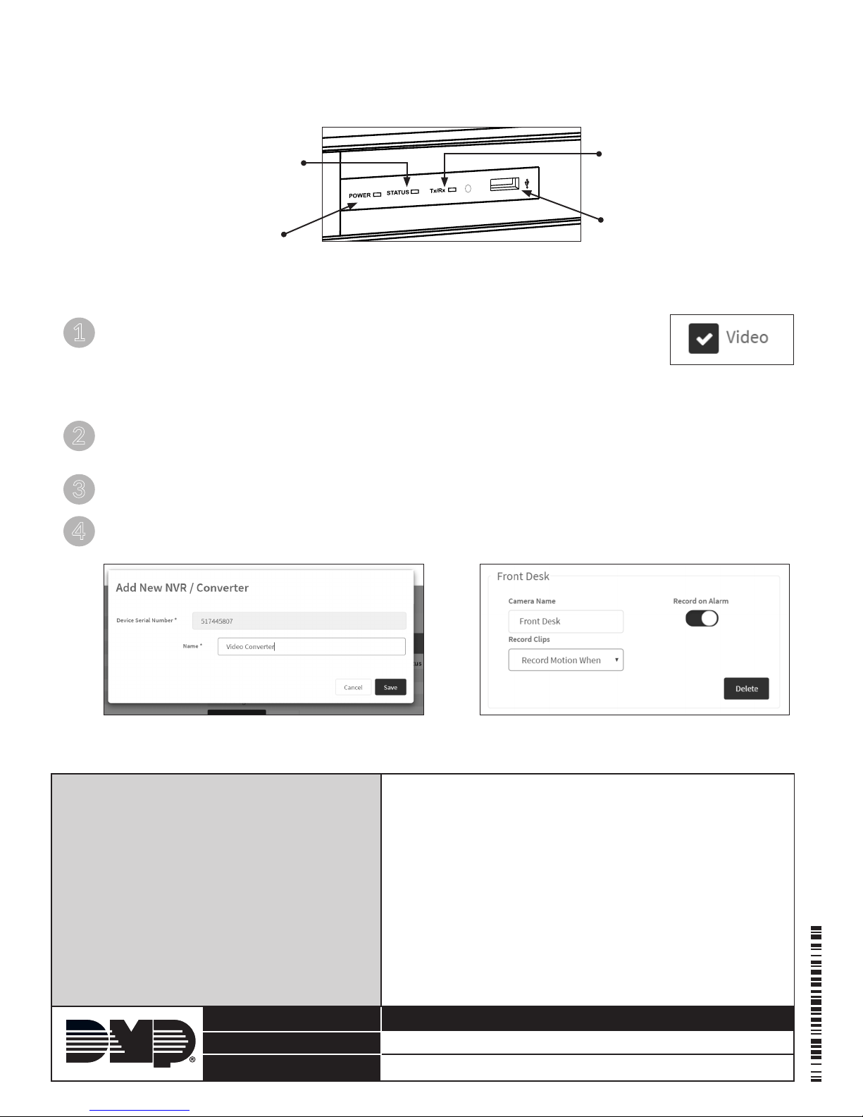
Understanding the Front of the Converter
Below, is a short description of each LED on the front of the V-4404A 4-Channel Converter, as well as the USB port.
Status LED
The indicator displays Red when
data is being read to or from the
Converter.
Power LED
The indicator displays Green
when power is applied to the
Converter.
Figure 3: Front Panel
Tx/Rx LED
The indicator shows
network activity.
USB Port
Allows a USB mouse or
keyboard to connect to
the Converter.
Adding the Analog Converter to a System
Log in to the dealeradmin.securecomwireless.com web site. Click on the desired system
1
account number to access the System Information screen.
Note: Video must be enabled before cameras may be added. If there is not a check
mark next to Video in System Information, click Edit at the bottom of the
window and place a check mark next to Video. Then click Save.
See Figure 4.
Click the Add NVR/Converter button. Enter the Serial Number from the bottom of the Analog Converter.
2
Then click Next. “Attempting to Connect” displays in the bottom corner of the Add New NVR/Converter
window. Name the Converter and click Save. See Figure 5.
Set the Time Zone. If you live in an area that observes Daylight Savings, click Observe Daylight Savings Time
3
to toggle the option on.
Change each camera’s name to describe its location and choose whether or not to have the camera record
4
on noise or motion. See Figure 6.
Figure 4:
Enable Video
Figure 5: Add the Converter Figure 6: Change Camera Settings
Specications
Temperature Range: -1 0°C to 55°C
14°F to 131°F
Humidity Range: 10% to 90%
Dimensions: 15”W x 11.4”D x 1.9”H
Weight: ≤2Kg(4.4lb)
800-641-4282
www.dmp.com 2500 North Partnership Boulevard
Designed, Engineered and
Assembled in U.S.A.
Compatible Cameras
All Analog Cameras
INTRUSION • FIRE • ACCESS • NETWORKS
Springeld, Missouri 65803-8877
16222
LT-1418 © 2016 Digital Monitoring Products, Inc.
 Loading...