

Page 1
INSTALLATION GUIDE
Screw
Network
V-4050D-1 Indoor/Outdoor Dome HD Video Camera
Description
The DMP V-4050D-1 is an indoor/outdoor wired/wireless
dome video camera that allows you to view live and recorded
clips through the Virtual Keypad App™. It also allows for motiontriggered video clip email notications. To activate the
camera, you need an active Dealer Admin account
at dealeradmin.securecomwireless.com.
Compatibility
• Any DMP system with an active Virtual Keypad App™
Included Components
• V-4050D-1 Camera
• Camera Mounting Base
• 12V Power Transformer
• Mounting Screws and Hex Key
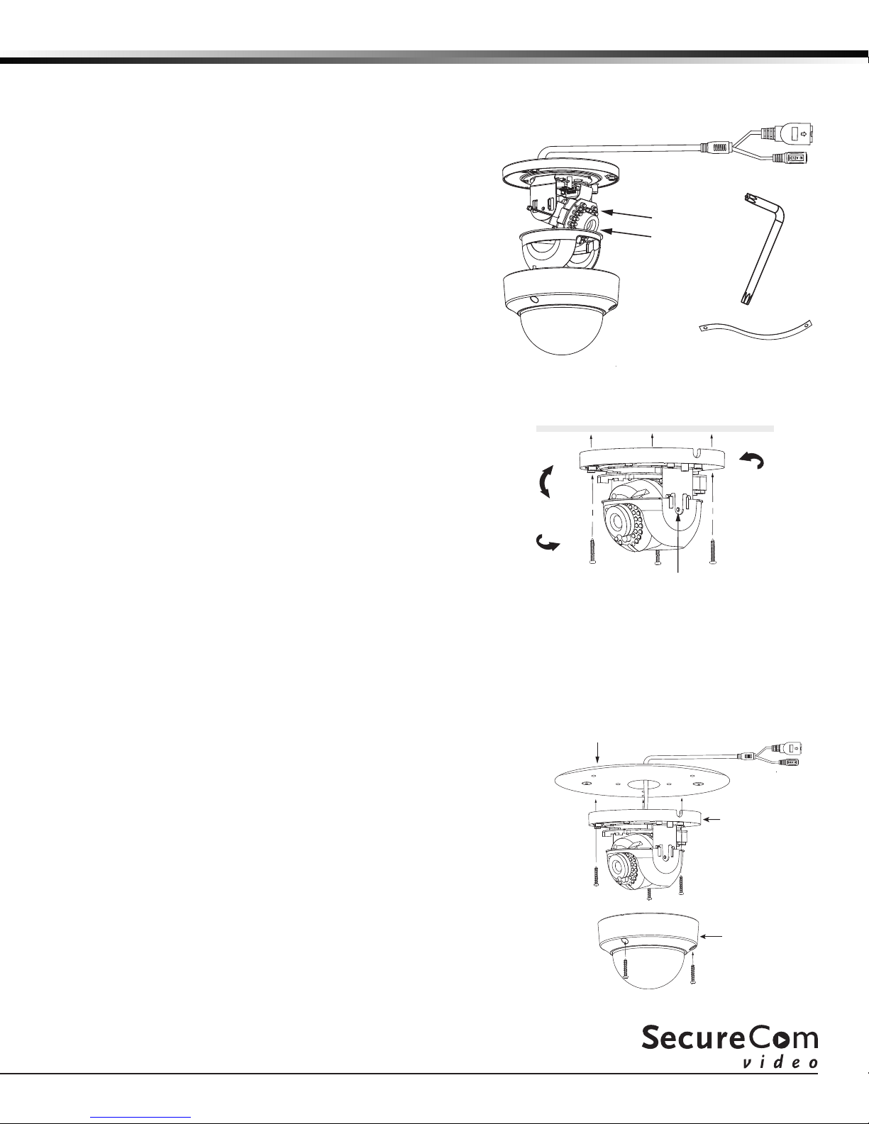
Mount the Camera
1. Use the supplied hex key to remove the cover from the
mounting base.
2. Using the included template, mark and drill the screw
holes for the mounting plate.
3. Attach the mounting base to the ceiling with the screws.
Note: If required, you can route cables through the
mounting base’s side opening.
4. Loosen the tilt lock screws and adjust the tilting position
(0° to 75°). Once adjusted, tighten the tilt lock screws.
See Figure 2.
5. Rotate the camera to adjust the pan angle (0° to 355°).
6. Rotate the lens to adjust the orientation of the
image (0° to 355°).
7. Reinstall the cover on the mounting base.
Tilt
0˚~ 90˚
Pan
0˚~ 355˚
Mounting
Base
IR LED’s
Lens
Cover
Safety Strap
Figure 1: Indoor/Outdoor
Dome HD Video Camera
Rotate
0˚~ 360˚
Tilt Lock
Figure 2: Mounting
and Adjustment
Interface
Power
Hex Key
Optional Wall/Ceiling V-4000 Mounting Plate
If you are mounting the camera to a standard single-gang box, the camera base may not fully cover the box. In these
situations, you have the option of using the V-4000 White Steel Mounting Plate which is designed to mount to the
single-gang box, providing full coverage. Follow the steps below to install the mounting plate:
Mounting Plate
1. Remove the cover to expose the inside of the camera.
2. Route the camera’s power and network cables through the
mounting plate and connect as necessary.
3. Place the mounting plate in the desired location.
4. Using the supplied screws, secure the mounting plate to the
single-gang box.
5. Using the supplied screws, secure the camera to the mounting
plate.
6. Secure the cover on the camera. See Figure 3.
Note: Refer to Mounting the Camera for lens adjustment.
Figure 3: Mount Using the
V-4000 Mounting Plate
Camera Base
Camera Cover
Page 2
Congure the Camera
The V-4050D-1 can be congured to communicate to the SecureCom Video server in several ways. Which option you
choose depends on whether or not a DMP wireless access point (WAP) is available. The following sections outline the
step-by-step processes for setting up a V-4050D-1 camera.
For a V-IP1006RR WAP:
Auto Pair
1. Verify that the V-IP1006RR WAP is powered.
2. Plug the 12V power supply into the camera power connection, then connect it
to a power outlet or connect to the PoE Ethernet cable. Auto pairing will begin
immediately.
Wireless Connection
1. Plug the 12V power supply into the camera power connection, then connect it to
a power outlet.
2. Use the supplied hex key to remove the cover from the mounting base.
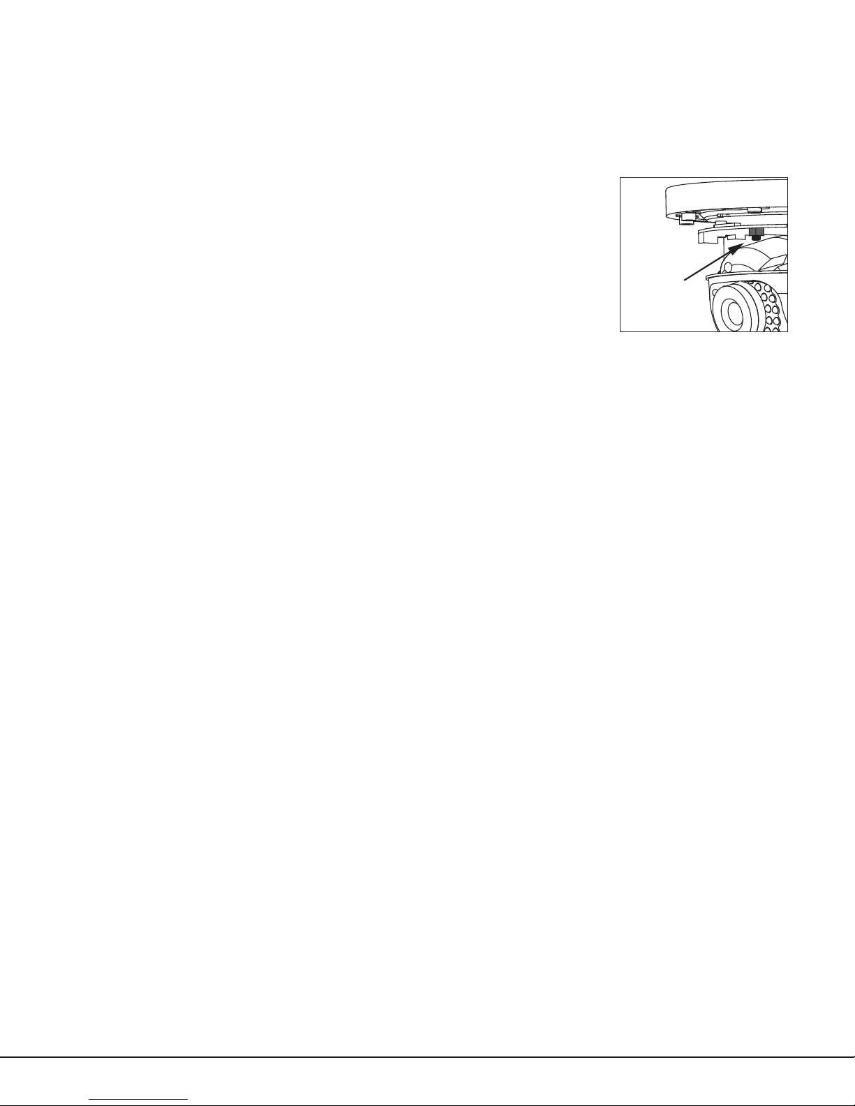
3. Press the WPS button on the back of the WAP for up to 1.5 seconds. The Security
LED will ash to indicate that the WAP is sending a security key to the camera.
4. Within 1 minute of pressing the WPS button on the WAP, press and hold the WPS/
RESET button on the camera for three seconds. See Figure 4. Once the
camera and router are fully connected, the WPS LED on the WAP turns on steady.
5. Reinstall the cover on the mounting base.
For a Non-DMP WAP with WPS:
1. Plug the 12V power supply into the camera power connection, then connect it to a power outlet or
connect the PoE Ethernet Cable.
2. Use the supplied hex key to remove the cover from the mounting base.
3. Refer to the router’s instruction manual to place the router in WPS mode.
4. Within 1 minute of pressing the WPS button on the WAP, press and hold the WPS
button on the camera for three seconds. See Figure 4. Once the camera and
router are fully connected, the WPS LED on the WAP turns on steady.
5. Reinstall the cover on the mounting base.
For a Hard-Wired Connection
1. Plug an Ethernet cable with an active Internet connection into the network interface cord on the camera before
powering the camera. See Figure 1.
2. Plug the 12V power supply into the camera power connection, then connect it to a power outlet or connect
the PoE Ethernet cable.
Note: Marking the Ethernet cable from the customer’s router to the WAP to help in network troubleshooting is
recommended.
WPS/RESET
Button
Figure 4: Camera
WPS/RESET Button
Activate the Camera through SecureCom Wireless
Once communication has been established, activate the camera at dealeradmin.securecomwireless.com.
1. Log in with your dealer login information at dealeradmin.securecomwireless.com and choose the customer.
2. Click Edit on the System Information screen to access the customer’s system settings.
3. Enable video by checking the Video check box. Click Save and the System Information screen displays.
4. Press Add New Camera and enter the MAC Address. This 12-digit number can be found on the bottom of the
camera. Click Next and enter the following information:
Name: The name that displays in the user’s app and video feed. This can be up to 16 characters long.
Time Zone: Select the time zone of the camera location.
Flip Image?: Select Yes if the camera image needs to be inverted due to the mounting position of the camera.
Clips: Enable Clips to allow this camera to record motion-triggered video clips to the SecureCom Video server.
• Choose Never Record Motion if you only want this camera to offer a live camera view through the
Virtual Keypad App™.
• Choose Always Record on Motion if you want this camera to record video clips any time it detects
motion.
SecureCom Video V-4050D-I Indoor/Outdoor Dome HD Installation Guide
2
Page 3

• Choose Record Motion When Armed if you want the camera to record motion-triggered clips only when
the system is armed. When the system is disarmed no clips will be recorded.
Record on alarm: When enabled, the camera will record video clips continuously during the rst minute after
the system is in alarm.
5. Click Save. This begins the activation process and an Activating status appears next to the camera name.
Press the refresh button to display the latest status. When the camera is active and communicating with the
SecureCom Video Server, it will have a status of Active and a check mark in the Network Ready column.
Viewing the Camera
To view the camera during installation, select the camera name under Video Devices on the System Information
screen to display a live video feed for the rst 60 minutes after activation. This allows the user to position the
camera in the desired location. Once 60 minutes has passed, the camera feed can only be seen through the user’s
Virtual Keypad App™.
Emailing Clips
If the user would like to be emailed video clips, enable this option. From the Customer Information screen, click
on the email address to go to the Edit User for Customer screen and then click Edit. Checking the Email Video
Clips box sends emails with a video clip attachment to the app user any time the video camera records a clip to the
SecureCom video server.
LED Operation
Red: The camera is detecting motion and recording clips.
Blue: The camera is not detecting motion and not recording clips.
V-4050D-I Indoor/Outdoor Dome HD Installation Guide SecureCom Video
3
Page 4

Specications
Sensor and Lens:
Image Sensor 1/3” CMOS Sensor
PIR Sensor Direction Range 65 ft.
Video Compression H.264, M-JPEG
Resolution 720p (1280 x 960)
Frame Rate Up to 30 frames per second
Network:
Wireless IEEE 802.11b/g/n;
WEP64/128 bit,
WPA/WPA2 Personal, WPS
Hardware:
Power Consumption 12VDC / Max 8W or PoE (802.3af)
Dimensions: Camera with stand 5.51” x 3.94”
Weight:
Camera with stand 2.2 lbs
17372
LT-1417 © 2017
 Loading...