

DMP Electronics Thinline Aqualite 7063, Thinline Aqualite 7000, Thinline Aqualite 7060, Thinline Aqualite 7160, Thinline Aqualite 7163 Installation And Programming Manual
...Page 1
7000 Series ThinlineTM and
AqualiteTM Keypad
INSTALLATION AND PROGRAMMING GUIDE
FRI 2: 52 PM
1 2 3 4
C
B
A
5 6 7 8
O
N
M
9 0 CMD
Z
Y
I
F
H
E
G
D
R
U
Q
T
P
S
K
C
A
B
L
K
J
X
W
V
R
E
T
N
E
Page 2

Page 3

TABLE OF CONTENTS
About the Keypad .........................1
Keypad Features ........................... 2
Enter Characters ........................... 4
Number Pad .......................................................... 4
Panic Key Options .............................................. 5
User Options Menu ............................................. 6
Install the Keypad ......................... 7
Remove the Cover .............................................. 7
Wire the Keypad.................................................. 8
Wire for Access Control ...................................11
Wire the Electronic Lock ................................13
Wire the 333 Suppressor .................................13
Program the Keypad ................... 16
Keypad Options ...................................................16
Custom Card Format .................. 20
Additional Programming ................................. 27
Test the Keypad ...........................28
End User Training ....................... 30
Keypad Arming and Disarming .....................31
Keypad Access Control ...................................33
Keypad Entry Delay ..........................................34
Wiring Specifications..................35
Keypad Specifications ............... 36
Public Card Formats ...................37
Readers and Credentials ............38
Compliance Specifications ....... 40
Accessories ..................................40
Certifications ................................41
FCC Information ......................... 42
Industry Canada Information .... 43
Page 4

Page 5

ABOUT THE KEYPAD
Thinline Series (7060, 7063, 7070, 7073, 7160, 7163, 7170, and 7173) and Aqualite Series
(7060A, 7063A, 7070A, and 7073A) LCD keypads oer flexible features and functionality.
Each keypad provides:
• Custom 16-character home or business name in the display
• Four 2-button panic keys
• AC Power/Armed LED
• 32-character display
• Backlit keyboard and DMP logo
• Internal speaker
• Red keyboard lighting in alarm conditions
• Simple harness connection to 4-wire keypad bus
• Optional backboxes for conduit or wall mount applications
Models 7070/A, 7073/A, 7170, and 7173
Provide four fully-programmable, Class B, Style A, supervised, power limited protection
zones that can be programmed for a variety of burglary and access control applications.
Models 7063/A, 7073/A, 7163, and 7173
Provide a built-in proximity card reader designed to read proximity credentials.
Models 7073/A and 7173
Provide a door strike relay and allow Wiegand input from external card readers.
7000 Series Installation and Programming Guide | Digital Monitoring Products, Inc. 1
Page 6
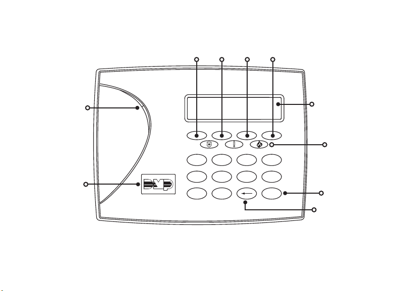
KEYPAD FEATURES
Select Keys
1 43
2
Armed/Power
LEDs
Proximity
Credential Reader
and Backlit Logo
FRI 2: 52 PM
1 2 3 4
C
B
A
5 6 7 8
O
N
M
9 0 CMD
Z
Y
Figure 1: 7000 Series LCD Keypad
Digital Monitoring Products, Inc | 7000 Series Installation and Programming Guide 2
Keypad Display/
Status List
Panic Keys
I
F
E
G
D
R
Q
P
S
B
L
H
K
J
X
U
W
T
V
R
E
K
T
C
N
A
E
Command
(CMD) Key
Back Arrow Key
Page 7
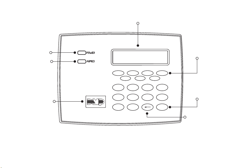
32-Character Display
Power LED
Armed LED
Proximity
Credential
Reader and
Backlit Logo
ABC SECURITY
FRI 2: 52 PM
1 2 3 4
C
B
A
5 6 7 8
D
O
N
M
P
9 0 CMD
Z
Y
I
F
H
E
G
R
U
Q
T
S
K
C
A
B
K
J
W
V
T
N
E
L
E
X
R
Select Keys
Command
Back Arrow
Figure 2: Thinline 7100 Series LCD Keypad
7000 Series Installation and Programming Guide | Digital Monitoring Products, Inc. 3
Page 8

ENTER CHARACTERS
NUMBER PAD
1. Choose a character from the table. Use the Greek Characters table if Greek was
selected as the keypad language setting.
2. Identify the Number the character correlates with and press that number on the
number pad.
3. Identify the Select Key for the character and press that select key on the keypad.
Press that select key again for the lowercase letter (Latin characters only).
4. When the desired character displays on the keypad, return to step 1 to enter
another character or press CMD if finished.
NUMBER
1 A B C ( [ {
2 D E F ) ] }
3 G H I ! ^ ~
4 J K L ? “ |
5 M N O / \ `
6 P Q R & $
7 S T U @ %
8 V W X , =
9 Y Z Space : _ ;
0 - + . ‘ * < # >
1 2 3 4
SELECT KEY
Table 1: Latin Characters
Digital Monitoring Products, Inc | 7000 Series Installation and Programming Guide 4
NUMBER
1 Α Β Γ ( [ {
2 Δ Ε Ζ ) ] }
3 Η Θ Ι ! ^ ~
4 Κ Λ Μ ? “ |
5 Ν Ξ Ο / \ `
6 Π Ρ Σ & $
7 Τ Υ Φ @ %
8 Χ Ψ Ω , =
9 Space Space Space : _ ;
0 - + . ‘ * < # >
1 2 3 4
Table 2: Greek Characters
SELECT KEY
Page 9

PANIC KEY OPTIONS
2-Button Panic Keys
All keypads oer a panic key function that allows users to send panic, emergency, or fire
reports to the central station in an emergency. Enable the panic key function in the keypad
user menu. Place the supplied icon stickers below the top row select keys. The user must
press and hold the two select keys for two seconds until a beep is heard.
Panic (left two select keys)—Zone 19 + Device Address
Emergency Non-Medical (center two select keys)—Zone 29 + Device Address
Fire (right two select keys)—Zone 39 + Device Address
7/0 Panic Keys
All keypads allow the user to initiate a panic alarm by pressing the 7 and 0 (zero) keys at
the same time for one-half (1/2) second. Enable the 7/0 Panic function in Installer Options.
When enabled, all keypads send a Zone Short message to the panel for the first zone of
the keypad address. When the keys are released, a Zone Restore message can be sent
from the initiating keypad. To produce a panic alarm, program the first zone of the keypad
address as a panic type (PN) in panel programming. Place a 1k Ohm end-of-line (EOL)
resistor, DMP Model 311, across the white/brown pair of zone wires on models 7070/A,
7073/A, 7170, and 7173. A Zone Restore message sends when the keys are released. The 1k
Ohm EOL resistor is not required on 7060/A, 7063/A, 7160, and 7163 keypads.
7000 Series Installation and Programming Guide | Digital Monitoring Products, Inc. 5
Page 10

USER OPTIONS MENU
To access the Options menu, press and hold the back arrow and CMD keys for 2 seconds.
Backlighting Brightness
Adjust the LCD display brightness level, power and armed LEDs, the green keyboard,
and the logo backlighting. At SET BRIGHTNESS, use the left select key to decrease the
brightness and the right select key to increase the brightness. If the brightness level is
lowered, it reverts to maximum intensity whenever a key is pressed. If no keys are pressed,
and the speaker has not sounded for 30 seconds, the user-selected brightness level
restores.
Internal Speaker Tone
Adjust the keypad internal speaker tone. At SET TONE, use the left select key to decrease
the tone and the right select key to increase the tone.
Internal Volume Level
Adjust the keypad internal speaker volume for key presses and entry delay tone
conditions. During alarm and trouble conditions, the volume is always at maximum level.
At SET VOLUME LEVEL, use the left select key to decrease the volume and the right select
key to increase the volume.
Model Number
Display the keypad model number, firmware version, and date.
Keypad Address
Display the current keypad address.
Digital Monitoring Products, Inc | 7000 Series Installation and Programming Guide 6
Page 11
INSTALL THE KEYPAD
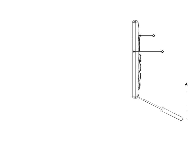
REMOVE THE COVER
1
The keypad housing is made up of two parts: the cover,
which contains the circuit board and components, and
the base.
To separate the keypad cover from the base, insert a
flathead screwdriver into one of the slots on the bottom
of the keypad and gently lift the screwdriver upward.
Repeat with the other slot. Gently separate the cover
from the base and set the cover containing the keypad
components aside. See Figure 3.
Figure 3: Separate the
Keypad Housing
7000 Series Installation and Programming Guide | Digital Monitoring Products, Inc. 7
Cover
Base
Page 12

WIRE THE KEYPAD
J5
Y/W
R
2
Each keypad model has specific wiring assignments. All zones are supervised. Use
1kOhm EOL resistors, DMP Model 311 on keypad zones 1-4. Locate the keypad model
below and refer to Figure 5 to wire the keypad.
Models 7060/A, 7063/A, 7160, and 7163
Supplied with a 4-wire harness for panel keypad bus connection.
Models 7070/A, 7073/A, 7170, and 7173
Supplied with a 12-wire data bus/zone harness. Four wires connect to the keypad bus.
The remaining eight wires are for the four zone inputs, four wires for each zone.
Models 7073/A and 7173
Supplied with a 5-wire output/reader harness and a 12-wire data bus/zone harness.
Firmly grasp the wires near the base and hold the outside
edges of the keypad housing. Line up the red and yellow
wires with the guides on the board to inset the connector
into the J5 keypad terminal. Observe wire colors when
connecting the red, yellow, green, and black wires to the
keypad bus. See Figure 4.
• Connect red wire to panel terminal 7
• Connect yellow wire to panel terminal 8
• Connect green wire to panel terminal 9
• Connect black wire to panel terminal 10
Digital Monitoring Products, Inc | 7000 Series Installation and Programming Guide 8
Figure 4: Wiring Harness
Page 13

Additional Power Supply
If the current draw for all keypads exceeds the panel output, provide additional current by
adding a Model 505-12 auxiliary power supply.
1. Connect all keypad black ground wires to the power supply negative terminal.
2. Run a jumper wire from the power supply negative terminal to the panel common
ground terminal.
3. Connect all keypad power (+12VDC) wires to the power supply positive terminal.
Do not connect the power supply positive terminal to any panel terminal. Refer to
the 505-12 Power Supply Installation Guide if needed (LT-0453).
Keypad Bus Monitor
For listed fire protective systems, the 893A Module or 277 Trouble Sounder must be
installed on the XR150/XR550 Series panel to monitor the keypad bus. It should be
programmed to sound when the keypad bus fails to operate.
7000 Series Installation and Programming Guide | Digital Monitoring Products, Inc. 9
Page 14
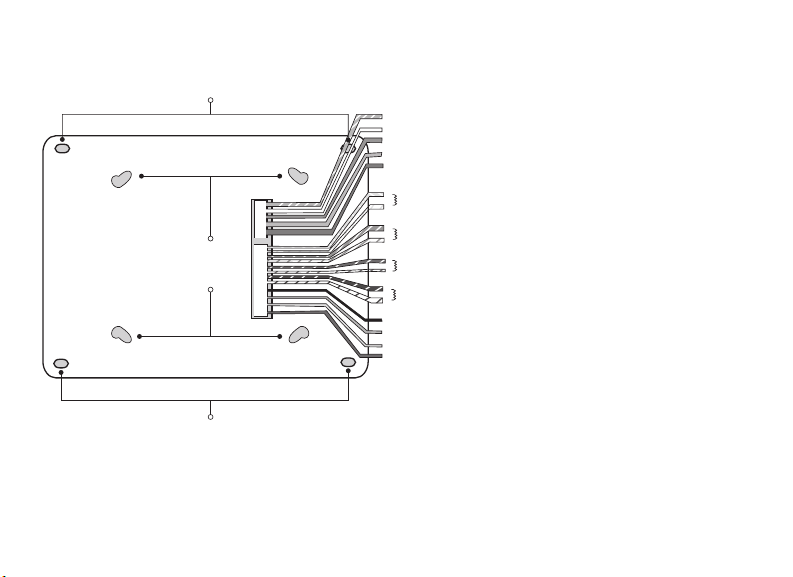
1K EOL
1K EOL
1K EOL
1K EOL
Green/White
– Connect Reader Data 0
White
– Connect Reader Data 1
Orange
– Door Strike N/O
Gray
–
Door Strike C
Violet
–
Door Strike N/C
Yellow/White
White/Yellow
Orange White
White/Orange
Red/White
White/Red
Brown/White
White/Brown
Black
– Ground
Green
– Receive Data
Yellow
– Send Data
Red
– Keypad Power
– Zone 4
– Zone 3
– Zone 2
– Zone 1
ExternalReader/Door Strike
7073/7073A, 7173 Keypads
All Keypads
Zones 1-4
7070/7070A, 7073/7073A, 7170/7173 Keypads
Surface and Backbox
Mounting Holes
Combined 4-square
and 3-gang switch box
Mounting Holes
Surface and Backbox
Mounting Holes
*All zones are supervised and suitable for fire applications.
*Maximum zone line impedence is 100 Ohms.
*Ground fault detected at 1420 Ohms or less.
Figure 5: Keypad Back Showing Wiring
Harness Assignments
Digital Monitoring Products, Inc | 7000 Series Installation and Programming Guide 10
Page 15

WIRE FOR ACCESS CONTROL
3
Internal Access Control Reader
The 7063/A, 7073/A, 7163, and 7173 keypads provide a built-in proximity card reader
that is compatible with most standard 125kHz proximity credentials. An external
13.56MHz proximity reader can be connected and will be compatible with 13.56MHz
proximity credentials. For a list of publicly supported card formats, see Public Card
Formats.
Note: Some proximity credentials are not compatible with DMP proximity
keypads. Test the intended proximity credentials with the application before
installation. DMP does not guarantee compatibility with credentials not
purchased from DMP.
External Access Control Reader
To accept Wiegand data input from other external card readers, connect a 12VDC
external reader to a 7073/A or 7173 keypad. Connect the red and black power wires
from the reader to the power wires from the panel. These connect in parallel with the
keypad power wires. Connect the reader (Data 1) wire to the white wire on the 5–wire
keypad cable. Connect the reader (Data 0) wire to the green/white wire on the 5–wire
keypad cable. See Figure 6.
7000 Series Installation and Programming Guide | Digital Monitoring Products, Inc. 11
Page 16

Green/White* - Connect Reader Data 0
White - Connect Reader Data 1
Orange - Door Strike Normally Open
Gray - Door Strike Common
Violet - Door Strike Normally Closed
s
NC
C
NO
WHT
GRN
Z4 -
Z4 +
Z3 -
Z3 +
Z2 -
Z2 +
Z1 -
Z1 +
BLK
GRN
YEL
RED
s
s
s
s
s
s
s
To Panel Keypad Bus
Digital Monitoring Products, Inc | 7000 Series Installation and Programming Guide 12
– Yellow & White
1K EOL
Zone 4
– Orange & White
1K EOL
1K EOL
1K EOL
(REX)
Zone 3
– Red & White
Zone 2
– Brown & White
(7/0 Panic)
Zone 1
Black – Ground
Green – Receive Data
Yellow – Send Data
Red – Keypad Power
Figure 6: Access Control Wiring
External Card
Reader
*Only the green/white,
white, black, and red
wires connect to the
external card reader.
Page 17

WIRE THE ELECTRONIC LOCK
4
The 7073/A and 7173 keypads provide one internal programmable Form C single
pole, double throw (SPDT) relay for controlling door strikes or magnetic locks. Three
wires on the 5-wire harness, violet normally closed (N/C), gray common (COM), and
orange normally open (N/O), allow you to connect devices to the relay. The Form C
relay draws up to 15mA of current and the contacts are rated for 1Amp at 30VDC
maximum.
WIRE THE 333 SUPPRESSOR
5
One Model 333 Suppressor is included with the 7073/A and 7173 keypads. If the
device being controlled by the relay is connected to the N/O and C wires, install the
suppressor on the N/O and C wires. If the device is connected to the N/C and C wires,
install the 333 on N/C and C wires. See Figure 7.
7000 Series Installation and Programming Guide | Digital Monitoring Products, Inc. 13
Page 18

Keypad
5-Wire Harness
Green/White – D0
White – D1
Orange – N/O
Gray – C
Violet – N/C
N/O
C
N/C
Common
–+
Magnetic Door Lock
Model 333
Supressor
Closed
Normally
Power Supply
Figure 7: 5-Wire Harness and 333 Suppressor Installation
Digital Monitoring Products, Inc | 7000 Series Installation and Programming Guide 14
Normally Open
DMP 505
Page 19

Door Strike Relay Operation
When the user code sent from the reader is verified by the panel, the keypad door
strike relay activates for five seconds. During this time, the access door connected to
Zone 2 must be opened to start the programmed entry/exit timer and Zone Bypass if
programmed and used. The five second door strike is panel programmable when the
keypad is used on an XR150/XR550 Series panel.
Zone 2 Door Contact with Bypass
If the door being released by the 7073/A and 7173 keypad is protected, you can provide
a programmed bypass time by connecting its contact to Zone 2 (white/red pair) on the
keypad and enabling the bypass feature. Door contacts may be N/C or N/O.
Zone 3 Request to Exit
You can also connect a N/O PIR (or other motion sensing device) or a mechanical switch
to Zone 3 (white/orange pair) on the 7073/A and 7173 keypad to provide Request to Exit
(REX) capability. When Zone 3 shorts, the keypad relay activates for 5 seconds. During
this time, the user can open the protected door to start the programmed Bypass entry/
exit timer. If the door is not opened within five seconds, the relay restores to its locked
state. A Zone 3 REX is inhibited for three seconds after the keypad reads a card and a
door strike occurs. This is to allow area entry and pass under a REX PIR.
7000 Series Installation and Programming Guide | Digital Monitoring Products, Inc. 15
Page 20

PROGRAM THE KEYPAD
Keypad Options and Keypad Diagnostic menus allow install and service technicians to
configure and test keypad operation. To access the installer options:
1. Hold down the back arrow and CMD keys for two seconds.
2. At SET BRIGHTNESS, enter 3577 (INST) and press CMD.
The display changes to KPD OPT KPD DIAG and STOP. The Keypad Options menu allows
you to set the keypad address, select Supervised or Unsupervised mode, change the
default keypad message, selectively enable the 2-button Panic keys, Bypass, REX, and set
entry card options.
All programming options display on all keypads. However, actual operation for some
programming options is restricted to the appropriate model.
KEYPAD OPTIONS
KPD KPD
OPT DIAG STOP
CURRENT KEYPAD
ADDRESS: 1
Keypad Options
To program keypad options, press KPD OPT.
Current Keypad Address
Set the current keypad address from 01 to 08 for
XT30/XT50/XR150 Series panels or 01 to 16 for XR550Series
panels. The default address is 01. To change the current
address, press any select key and enter the new address. Do
not enter a leading zero for addresses 01 to 09.
Digital Monitoring Products, Inc | 7000 Series Installation and Programming Guide 16
Page 21

KEYPAD MODE:
*SUP UNSUP
Keypad Mode
Keypads with programmed zones must be supervised and
cannot share an address with other keypads. Unsupervised
keypads can operate together sharing the same address, but
cannot be used when Device Fail Output has a programmed
value other than zero. To select a keypad mode, press the
select key under SUP or UNSUP. An asterisk appears next to
the selected option.
DEFAULT KPD MSG:
Default Keypad Message
Enter a custom message of up to 16characters to appear at
the top of the keypad display. Press any select key, enter a
new message, and press CMD.
ARM PANIC KEYS:
*PN EM *FI
Arm Panic Keys
Use this option to configure the select keys as two-button
panic keys. To enable or disable a panic option, press
the select key under the desired name: PN (panic), EM
(emergency), and FI (fire). Press the select key again to
disable the panic option. Once the panic option is enabled,
an asterisk displays next to the selected option(s).
7/0 PANIC
ENABLE: NO
7/0 Panic
Press the fourth select key to choose YES, configuring the
7and 0 keys as two-button panic keys. Select NO to disable
the option. Default is NO.
7000 Series Installation and Programming Guide | Digital Monitoring Products, Inc. 17
Page 22

ACTIVATE ZONE 2
BYPASS? NO
ZONE 2 BYPASS
TIME: 40
RELOCK ZONE 2
CHANGE: NO YES
Activate Zone 2 Bypass (7073/A, 7173 only)
Select YES to activate the zone 2 bypass operation.
Selecting NO allows standard zone operation on zone 2. The
default is NO.
Zone 2 Bypass Time (7073/A, 7173 only)
Enter the number of bypass seconds to elapse before the
bypass timer expires. Range is 20-250 seconds. Press any
select key to enter the number of seconds. Once the door
strike relay is activated, the user has five seconds to open
the door connected to zone 2. The zone is then bypassed for
the programmed time or until the contact restores to normal.
Ten seconds prior to the expiration of the bypass time, the
keypad beeps if the door is still open. If the door remains
open when the timer expires, a zone open/short is sent to
the panel for zone 2. Default is 40 seconds.
Relock on Zone 2 Fault? (7073/A, 7173 only)
Select NO to leave the relay on when zone 2 faults to an
open or short condition during bypass. Select YES to turn
the relay o when zone 2 faults open or short during bypass.
Default is NO.
Digital Monitoring Products, Inc | 7000 Series Installation and Programming Guide 18
Page 23

ACTIVATE ZONE 3
EXIT: NO YES
Activate Zone 3 Exit (7073/A, 7173)
Select YES to enable the Request to Exit feature on zone
3. When zone 3 shorts, the keypad relay activates. During
this time, the user can open the protected door to start
the programmed bypass entry/exit timer. If the door is not
opened within the time programmed in the Zone 3 REX
Strike Time, the relay restores the door to its locked state.
No panel programming is required.
ZONE 3 REX STRIKE
TIME: 5
Zone 3 REX Strike Time (7073/A, 7173)
Enter the number of REX seconds to elapse. Range is
5-250seconds. Press any select key to clear the keypad
display and enter the number of seconds. The default is 5.
ALL?: NO YES
DELAY: 2
ALL? NO YES (7063/A, 7073/A, 7163, 7173)
Select the number of seconds (1-9) the keypad should
wait when an area system displays ALL? NO YES during
arming/disarming or a HOME/SLEEP/AWAY system waits
during arming only. If NO or YES, or HOME, SLEEP, or
AWAY is not manually selected before the delay expires,
the keypad automatically selects YES or AWAY. Select zero
(0) to disable this feature. The delay also occurs when any
credential is presented for arming the Home/Sleep/Away
system. Default is 2.
7000 Series Installation and Programming Guide | Digital Monitoring Products, Inc. 19
Page 24

CUSTOM CARD FORMAT
Note: Custom card format programming options are only available on 7063/A,
7073/A, 7163, and 7173 keypads.
CARD FORMATS
DMP CUSTOM ANY
Card Formats
Select DMP to allow credentials that use a 26-45bit data
string. The menu advances to REQUIRE SITE.
Select CUSTOM to disable DMP format and program slots 1-8
as needed. The menu advances to FORMAT NO.
Select ANY to allow all Wiegand card reads to activate the
door strike relay. The door strike relay is activated for the
length of time programmed in ZN3 REX TIME. No user code
information is sent to the panel. The menu advances to NO
COMM WITH PNL.
The default card format is DMP.
Digital Monitoring Products, Inc | 7000 Series Installation and Programming Guide 20
Page 25

CARD FORMATS
FORMAT NO: -
Card Format Number
Select the slot number (1-8) that you want to program
for a custom non-DMP card format. The format that is
programmed into slot 1 is the default format. In the event that
a card with an unrecognized format is used, that card will be
read in the format that is programmed in slot 1. To restrict
card reads to specific formats, only program slots 2-8.
See Public Card Formats for some publicly available card
formats that can be used with the keypad. Other private or
custom formats may also be compatible. Please contact the
credential supplier or manufacturer for the bit structure.
Note: If you select slot 1 and you are upgrading from
XRpanel version 182 or earlier, FORMAT NAME will
automatically be named SINGLE CARD FORMAT and
WIEGAND CODE LENGTH will default to 45.
7000 Series Installation and Programming Guide | Digital Monitoring Products, Inc. 21
Page 26

FORMAT NAME
*UNUSED*
WIEGAND CODE
LENGTH: 26
Format Name
Press any select area to rename the card format. Press CMD
to save and advance.
Wiegand Code Length
When using a custom credential, enter the total number of
bits to be received in Wiegand code including parity bits.
Press any select key or area to enter a number between
1-255to equal the number of bits. Default is 26bits.
An access card contains data bits for a site code, user code,
and start/stop/parity bits. The starting position, location, and
code length must be determined and programmed into the
keypad. See Figure8.
01110101101101010001100111
Digital Monitoring Products, Inc | 7000 Series Installation and Programming Guide 22
First Bit
Received
Position = 0
Site Code
Position = 1
Length = 8
In this example the Wiegand Code Length = 26 bits.
Figure8: Wiegand Data Stream Bit Location
User Code
Position = 9
Length = 16
Position = 25
Last Bit
Received
Page 27

SITE CODE
POS: 1 LEN: 8
USER CODE
POS: 9 LEN: 16
REQUIRE SITE
CODE: NO YES
7000 Series Installation and Programming Guide | Digital Monitoring Products, Inc. 23
Site Code Position and Length
Enter the site code start position and length in the data
string. Press select area 2 to clear the site code start position
and enter a number between 0-255. Press CMD to save.
Default is 1.
Press select area 4 to clear the site code length and enter a
number between 1-24. Press CMD to save. Default is 8.
User Code Position and Length
Define the user code start bit position and length. Press
select area 2 to clear the user code position and enter a
number between 0-255. Press CMD to save. Default is 9.
Press select area 4 to clear the user code length and enter a
number between 16-64. Press CMD to save. The default is the
DMP value of 16.
Require Site Code
Press the top row select key or area under YES to use a site
code and press CMD to view the site code entry display.
Press NO to advance to NO OF USER CODE DIGITS. Default
is NO.
In addition to user code verification, door access is only
granted when any one site code programmed at the SITE
CODE ENTRY option matches the site code received in the
Wiegand string.
Page 28

SITE CODE 1:
NO OF USER CODE
DIGITS: 5
Site Code Display
You can program up to eight 8-digit site codes. The site code
range is 0-16,777,214.
In the keypad display, enter site code 1 and press CMD. The
display will ask for site code 2 followed by site code 3 and
so on. When you have selected the site code you want to
change, press CMD.
Number of User Code Digits
The keypad recognizes user codes from 4-12digits long.
Press any top row select key or area to enter a user code
digit length. This number must match the user code number
length being programmed in the panel. The device will
recommend a number of user code digits based on the user
code length. Default is 5.
All bits are read and converted into a decimal number string.
The number string is left padded with 0 (zero) if needed for
long user code lengths.
Example: # decoded 1234567
10 digits 0001234567
4 digits 4567
Digital Monitoring Products, Inc | 7000 Series Installation and Programming Guide 24
Page 29

NO COMM WITH PNL
OFF SITE ANY ON
No Communication with Panel
Define the relay action when communication with the panel
has not occurred for 5seconds. Default is OFF. Press any
select key or area to change the default relay action:
Press the first select key or area to choose OFF (Relay
Always O). The relay does not turn on when any Wiegand
string is received. OFF does not aect any REX operation. If
communication is lost during a door strike, the relay remains
on for the door strike duration but turns o at the end of the
door strike timer.
Press the second select key or area to choose SITE (Accept
Site Code). Door access is granted when the Wiegand site
code string received matches any site code programmed at
SITE CODE DISPLAY. Refer to REQUIRE SITE CODE for more
information.
Press the third select key or area to choose ANY (Any
Wiegand Read). Access is granted when any Wiegand string
is received.
Press the fourth select key or area to choose ON (Relay
Always On). The relay is always on. Press CMD to display the
next action.
NO COMM WITH PNL
LAST
7000 Series Installation and Programming Guide | Digital Monitoring Products, Inc. 25
Press the first select key or area to choose LAST (Keep Last
State). The relay remains in the same state and does not
change when communication is lost.
Page 30

KYPD LANGUAGE:
LANG: ENGLSH
KYPD LANGUAGE:
ENG SPN FRN DUT
KYPD LANGUAGE:
EΛΛ CZK
Keypad Language
Define the keypad’s language. Default is ENGLSH.
Press any select key to change the language options.
Press select key 1 to select English. Press select key 2 to
select Spanish. Press select key 3 to select French. Press
select key 4 to select Dutch.
Press CMD to advance the language options.
Press select key 1 to select Greek. Press select key 2 to select
Czech.
Digital Monitoring Products, Inc | 7000 Series Installation and Programming Guide 26
Page 31

ADDITIONAL PROGRAMMING
Users can manually enter their user code into the keypad which then verifies the user code
and its authority with the panel. The 7073/A and 7173 activate the on-board Form C relay
releasing a door strike or magnetic lock. To provide added flexibility, the keypad allows
connection of an external Wiegand output compatible reader.
Proximity Credential Compatibility
DMP keypads with internal proximity readers are compatible with most standard 125kHz
proximity credentials. An external 13.56MHz proximity reader can be connected and will
be compatible with 13.56MHz proximity credentials. For a list of publicly supported card
formats, see Public Card Formats.
Note: Some proximity credentials are not compatible with DMP proximity keypads.
Test the intended proximity credentials with the application before installation. DMP
does not guarantee compatibility with credentials not purchased from DMP.
Program a Credential
1. Access the User Menu by pressing CMD until MENU? NO YES displays. Choose
YES, and present your proximity credential to the reader or manually enter your
user code at the keypad.
2. Press CMD until USER CODES? displays.
3. Press any select key. Choose ADD.
4. At ENTER CODE: -, present the credential to the reader. The keypad works by
reading the user code from the data string sent by the access control reader.
7000 Series Installation and Programming Guide | Digital Monitoring Products, Inc. 27
Page 32

TEST THE KEYPAD
Test the keypad to ensure alarm backlighting, individual shortcut keys, and any
programmed zones work. To begin testing, access the Installer Options menu. Hold down
the back arrow and CMD keys at the same time until SET BRIGHTNESS displays. Enter
3577 and press CMD.
KPD KPD
OPT DIAG STOP
PRESS KEY TO
TEST
Keypad Diagnostics
Press the select key under KPD DIAG. The keypad lights all
display segments and illuminates the keyboard in red. The
display backlighting then changes to green. The keypad
alternates between these two states for approximately two
minutes. Press CMD at any time to begin testing individual
keys.
Test Individual Keys
The display changes to PRESS KEY TO TEST. This option
tests each key on the keyboard to ensure it is operating
properly. Press and hold each key for two seconds. The key
number being held appears in the display. Verify the correct
number displays before testing the next key.
Digital Monitoring Products, Inc | 7000 Series Installation and Programming Guide 28
Page 33

Z1 OPEN Z2 OPEN
Z3 OPEN Z4 OPEN
Zone Test (7070, 7073/A, 7170, 7173)
This option allows the keypads to display the current
electrical status of the four protection zones. The status is
shown as OPEN, SHRT, or OKAY . The zone test displays on
the other keypads but is not operational.
INPUT WIEGAND
Input Wiegand (7063/A, 7073/A, 7163, 7173)
This option tests the internal and external reader input from
proximity credentials. The display shows OK AY each time a
good proximity read is received.
Exiting the Installer Options
When done, press CMD once to return to the Installer Options screen. Press the select key
under STOP to exit the Installer Options function.
7000 Series Installation and Programming Guide | Digital Monitoring Products, Inc. 29
Page 34

END USER TRAINING
This section covers 7063/A, 7073/A, 7163, and 7173 keypads and contains three sections:
• Keypad Arming and Disarming
• Keypad Access Control
• Keypad Entry Delay
All of the examples displayed assume that CLOSING CODE is YES in panel programming.
Figures 9 through 12 show the user presenting a card to the keypad. When an external
reader is connected to a 7073/A and a 7173 keypad, the user presents a card to the reader
rather than to the keypad.
Digital Monitoring Products, Inc | 7000 Series Installation and Programming Guide 30
Page 35

KEYPAD ARMING AND DISARMING
Area System Arming and Disarming
1. Press CMD until the keypad displays ARM DISARM.
2. Press the select key under the preferred option.
3. The keypad displays ENTER CODE: -. The user presents their card to the reader.
Once validated by the system, all areas assigned to that code arm or disarm automatically
and the 7073/A and 7173 keypad door strike relay activates. See Figure 9.
ABC SECURITY
ARM DISARM
Select NO to arm or disarm individual areas.
Select YES, or simply wait, to automatically arm or disarm all areas for which you are authorized.
ABC SECURITY
ENTER CODE: –
ABC SECURITY
ALL? NO YES
Figure 9: Area Arming and Disarming
7000 Series Installation and Programming Guide | Digital Monitoring Products, Inc. 31
Page 36

All/Perimeter System Arming and Disarming
Present the card to the reader or press CMD, the keypad displays DISARM? or PERIM ALL
(when arming). Press the select key under the desired option. The keypad displays
ENTER CODE: -. Present the card to the reader. Once validated by the system, the
selected areas arm or disarm automatically. On 7073/A and 7173 keypads, the Door Strike
relay then activates.
Home/Away System Arming and Disarming
Present your card to the reader. If the system is armed, once the card is validated, all areas
are disarmed and the keypad displays ALL SYSTEM OFF. If the system is disarmed when
you present your card, once the card is validated, HOME SLEEP AWAY displays. Manually
select HOME, SLEEP, AWAY or after a short time-out, all areas automatically arm in the
AWAY mode.
PERIM ALL
The system arms or disarms the areas and
activates the door strike relay on the 7073 or 7073A keypad.
Figure 10: All Perimeter Arming and Disarming
Digital Monitoring Products, Inc | 7000 Series Installation and Programming Guide 32
Page 37

KEYPAD ACCESS CONTROL
Area and All/Perimeter Door Strike
From the Status List, present your card to the reader. Once the system validates the card,
the Door Strike relay activates. Home/Away systems only activate the 7073/A, and 7173
Door Strike relay when arming and disarming.
ABC SECURITY
MON 10:20 AM
Typically, the relay activates for 5 seconds during which
While the keypad displays the
Status List, present your access card.
Figure 11: Present Access Card
7000 Series Installation and Programming Guide | Digital Monitoring Products, Inc. 33
time you can open the door. Once you open the door,
you have 40 seconds to exit and close the door before
the Zone 2 Bypass expires.
Page 38

KEYPAD ENTRY DELAY
All Systems
Once the entry delay starts, the keypad sounds an entry tone and displays
ENTER CODE: - . Present your card to the reader. Once validated, the system disarms all
areas accessible by you and activates the 7073/7073A/7173 Door Strike relay. Area
systems provide a delay to allow selected areas only to be disarmed. See Keypad Arming
and Disarming.
ABC SECURITY
ENTER CODE: –
Entry delay starts.
The System disarms the area and activates the Door Strike Relay.
Figure 12: Entry Delay
Digital Monitoring Products, Inc | 7000 Series Installation and Programming Guide 34
Page 39

WIRING SPECIFICATIONS
When planning a keypad bus installation, keep in mind the following specifications:
• DMP recommends using 18 or 22 AWG unshielded wire for all keypad and LX-Bus
circuits. Do not use twisted pair or shielded wire for LX-Bus and keypad bus data
circuits. To maintain auxiliary power integrity when using 22-gauge wire, do not
exceed 500 feet. When using 18-gauge wire, do not exceed 1,000 feet. Install an
additional power supply to increase the wire length or add devices.
• Maximum distance for any one circuit (length of wire) is 2,500 feet regardless of the
wire gauge. This distance can be in the form of one long wire run or multiple branches
with all wiring totaling no more than 2,500 feet. As wire distance from the panel
increases, DC voltage on the wire decreases.
• Maximum number of devices per 2,500 feet circuit is 40.
Note: Each panel allows a specific number of supervised keypads. Add
additional keypads in the unsupervised mode. Refer to the panel installation
guide for the specific number of supervised keypads allowed.
• Maximum voltage drop between the panel (or auxiliary power supply) and any device
is 2VDC. If the voltage at any device is less than the required level, add an auxiliary
power supply at the end of the circuit. When voltage is too low, the devices cannot
operate properly.
7000 Series Installation and Programming Guide | Digital Monitoring Products, Inc. 35
Page 40

KEYPAD SPECIFICATIONS
MODEL
7060/A,
7160
7063/A,
7163
7070/A,
7170
7073/A,
7173
NORMAL/
STANDBY
CURRENT
72mA 87mA
85mA 100mA X
72mA+1.6mA
per active zone
85mA+1.6mA
per active zone
ALARM
CURRENT
87mA+2mA
per active
zone
100mA+2mA
per active
zone
Digital Monitoring Products, Inc | 7000 Series Installation and Programming Guide 36
FOUR
ZONES
X
X X X X
INTERNAL
PROX
READER
WIEGAND
INPUT
INTERNAL
DOOR
STRIKE
RELAY
Page 41

PUBLIC CARD FORMATS
CARD
FORMAT
H10301 26 BIT 26 1 8 9 16 5
H10302 37 BIT
W/FAC
H10304 37 BIT
W/O FA C
FARPOINTE
39 BIT
CORPORATE
1000 35 BIT
CORPORATE
1000 48 BIT
7000 Series Installation and Programming Guide | Digital Monitoring Products, Inc. 37
WIEGAND
CODE
LENGTH
37 1 16 17 19 6
37 0 0 1 35 12
39 1 17 18 20 7
35 2 12 14 20 6
48 2 22 24 23 7
SITE
CODE
POSITION
SITE
CODE
LENGTH
USER
CODE
POSITION
USER
CODE
LENGTH
USER
CODE
DIGITS
Page 42

READERS AND CREDENTIALS
125 KHZ PROXIMITY READERS
125 KHZ PROXIMITY CREDENTIALS
P-300 CASCADE PROXIMITY
READER
P-500 ALPS PROXIMITY READER
P-640 PATAGONIA PROXIMITY
READER WITH KEYPAD
MP-5365 MINIPROX™ PROXIMITY
READER
MX-5375 MAXIPROX® PROXIMITY
READER
PP-6005B PROXPOINT® PLUS
PROXIMITY READER
PP-5355 PROXPRO PROXIMITY
READER WITH KEYPAD
PR-5455 PROXPRO® II PROXIMITY
READER
TL-5395 THINLINE II® PROXIMITY
READER
Digital Monitoring Products, Inc | 7000 Series Installation and Programming Guide 38
PSC-1 STANDARD LIGHT
PROXIMITY CARD
PSK-3 PROXIMITY KEY
RING TAG
PSM-2P ISO IMAGEABLE
PROXIMITY CARD
1306 PROX PATCH™
1326 PROXCARD II®
CARD
1346 PROXKEY III®
ACCESS DEVICE
1351 PROXPASS®
1386 ISOPROX II® CARD
Page 43

13.56 MHZ SMARTCARD READERS
13.56 MHZ SMARTCARD CREDENTIALS
DELTA3 FARPOINTE SMARTCARD
READER
DELTA5 FARPOINTE SMARTCARD
READER
DELTA5.3 FARPOINTE SMARTCARD
READER
DELTA6.4 FARPOINTE SMARTCARD
READER
DC1-1 FARPOINTE CLAMSHELL
SMARTCARD
DM1-3 FARPOINTE IMAGEABLE
SMARTCARD
DE2 FARPOINTE MIFARE®
DESFIRE® EV1
SMARTCARD
DK1-3 FARPOINTE KEY FOB
SMARTCARD
7000 Series Installation and Programming Guide | Digital Monitoring Products, Inc. 39
Page 44

COMPLIANCE SPECIFICATIONS
ULC Commercial Burglary for XR150/XR550 Series Panels
The keypad zones cannot be used for ULC listed applications.
Specifications
Operating Voltage 12VDC
Thinline/Aqualite Dimensions 7” W x 5.25” H x 0.5” D
Compatibility
All keypads are compatible with all DMP panels.
ACCESSORIES
Backboxes
695 or 696 Keypad Backbox 777 protective keypad cover
Keypad Wiring Harness
300 4-wire harness 300-5 5-wire harness
300-12 12-wire harness 300-512 12-wire harness, 5 ft. long
330 4-wire dual end harness
Digital Monitoring Products, Inc | 7000 Series Installation and Programming Guide 40
Page 45

CERTIFICATIONS
California State Fire Marshall (CSFM)
FCC Part 15 RFID Reader FCC ID: CCKPC0086—Thinline and Aqualite
Industry Canada ID: 5251A-PC0086—Thinline and Aqualite
New York City (FDNY COA #6167)—Only for keypads with zones
Underwriters Laboratory (UL) Listed
ANSI/UL 294 Access Control System Units
Level I Destructive Attack and Line Security
Level IV Endurance and Standby Power
ANSI/UL 365 Police Connected Burglar
ANSI/UL 609 Local Burglar
ANSI/UL 1023 Household Burglar
ANSI/UL 1076 Proprietary Burglar
ANSI/UL 1610 Central Station Burglar
ANSI/UL 1635 Digital Burglar
ANSI/UL 985 Household Fire Warning
ANSI/UL 864 Fire Protective Signaling
ULC 5545 Household Fire
ULC Subject-C1023 Household Burglar
ULC/ORD-C1076 Proprietary Burglar
ULC S304 Central Station Burglar
7000 Series Installation and Programming Guide | Digital Monitoring Products, Inc. 41
Page 46

FCC INFORMATION
This device complies with Part 15 of the FCC Rules. Operation is subject to the following two conditions:
1. This device may not cause harmful interference, and
2. This device must accept any interference received, including interference that may cause
undesired operation.
Changes or modifications made by the user and not expressly approved by the party responsible for
compliance could void the user’s authority to operate the equipment.
Note: This equipment has been tested and found to comply with the limits for a Class B digital
device, pursuant to part 15 of the FCC Rules. These limits are designed to provide reasonable
protection against harmful interference in a residential installation. This equipment generates,
uses and can radiate radio frequency energy and, if not installed and used in accordance with
the instructions, may cause harmful interference to radio communications. However, there is
no guarantee that interference will not occur in a particular installation. If this equipment does
cause harmful interference to radio or television reception, which can be determined by turning
the equipment o and on, the user is encouraged to try to correct the interference by one or
more of the following measures:
• Reorient or relocate the receiving antenna.
• Increase the separation between the equipment and receiver.
• Connect the equipment into an outlet on a circuit dierent from that to which the receiver is
connected.
• Consult the dealer or an experienced radio/TV technician for help.
Digital Monitoring Products, Inc | 7000 Series Installation and Programming Guide 42
Page 47

INDUSTRY CANADA INFORMATION
This device complies with Industry Canada License-exempt RSS standard(s). Operation is subject to the
following two conditions:
1. This device may not cause interference, and
2. This device must accept any interference, including interference that may cause undesired
operation of the device.
Le présent appareil est conforme aux CNR d’Industrie Canada applicables aux appareils radio exempts
de licence. L’exploitation est autorisée aux deux conditions suivantes:
1. l’appareil ne doit pas produire de brouillage, et
2. l’utilisateur de l’appareil doit accepter tout brouillage radioélectrique subi, même si le
brouillage est susceptible d’en compromettre le fonctionnement.
This system has been evaluated for RF Exposure per RSS-102 and is in compliance with the limits
specified by Health Canada Safety Code 6. The system must be installed at a minimum separation
distance from the antenna to a general bystander of 7.87 inches (20 cm) to maintain compliance with
the General Population limits.
L’exposition aux radiofréquences de ce système a été évaluée selon la norme RSS-102 et est jugée
conforme aux limites établies par le Code de sécurité 6 de Santé Canada. Le système doit être installé
à une distance minimale de 7.87 pouces (20 cm) séparant l’antenne d’une personne présente en
conformité avec les limites permises d’exposition du grand public.
7000 Series Installation and Programming Guide | Digital Monitoring Products, Inc. 43
Page 48

LT-0883 19314 1.04 © 2019 Digital Monitoring Products, Inc.
 Loading...