

DMP Electronics 7000INT Series, International Thinline 7063-WINT, International Thinline 7060-WINT, International Thinline 7073-WINT Installation And Programming Manual
Page 1
7000INT Series
International ThinlineTM Keypad
INSTALLATION AND PROGRAMMING GUIDE
FRI 2: 52 PM
1 2 3 4
C
B
A
5 6 7 8
O
N
M
9 0 CMD
Z
Y
I
F
H
E
G
D
R
U
Q
T
P
S
K
C
A
B
L
K
J
X
W
V
R
E
T
N
E
Page 2

Page 3

TABLE OF CONTENTS
About the Keypad .........................1
7060-WINT .............................................................1
7063-WINT .............................................................1
7073-WINT .............................................................1
Keypad Features ........................... 2
Enter Characters ........................... 3
Number Pad .......................................................... 3
Install the Keypad .........................4
Remove the Cover .............................................. 4
Wire the Keypad.................................................. 5
Model 7060-WINT and 7063-WINT ............ 5
Model 7073-WINT ............................................... 5
Wire for Access Control ................................... 7
Internal Access Control Reader ..................... 7
External Access Control Reader ................... 7
Wire the Electronic Lock ................................ 9
Wire the 333 Suppressor ................................. 9
Mount the Keypad ........................11
Tamper Protection .............................................. 11
Program the Keypad ................... 13
Keypad Options ...................................................13
Custom Card Format ........................18
Additional Programming .................................24
Proximity Credential Compatibility ........... 24
Program a Credential .......................................24
Test the Keypad ...........................25
Arm and Disarm the System ..........................27
Area System Type .............................................. 27
All/Perimeter System Type ............................ 27
End User Training ........................27
Home/Sleep/Away System Type ................. 28
Use Access Control ........................................... 28
Access an Area Using the Door Strike .......28
Use Entry Delay When Disarming ............... 28
Page 4

Wiring Specifications.................. 29
Keypad Specifications ................ 30
Public Card Formats ....................31
Readers and Credentials ............ 32
Compliance Specifications ........ 34
Specifications ...................................................... 34
Compatibility ....................................................... 34
What Is Included? .............................................. 34
Accessories...........................................................34
International Certifications ........ 35
Security Grade 3 .................................................35
Environment Class II .........................................35
Intertek (ETL) Listed .........................................35
Page 5

ABOUT THE KEYPAD
7000INT Series International Thinline Keypads oer flexible features and functionality.
Each keypad provides a custom home or business name in the 32-character LCD display,
optional panic keys, an AC Power/Armed LED, a backlit keyboard and logo display that
turns red in alarm conditions, an internal speaker, a simple terminal connection to a 4-wire
keypad bus, and optional backboxes for conduit or wall mount applications. Each model
provides its own distinct functionality. See Figure 1 for keypad features.
7060-WINT
Basic keypad functionality.
Digital Monitoring Products, Inc | 7000INT Series Installation and Programming Guide 1
7063-WINT
Built-in proximity card
reader designed to read
proximity credentials.
7073-WINT
Provides a door strike relay
and allows Wiegand input
from external card readers.
Provides a built-in proximity
card reader designed to
read proximity credentials.
Four fully-programmable
Class B, Style A, supervised,
power limited protection
zones that can be
programmed for a variety
of burglary and access
control applications.
Page 6
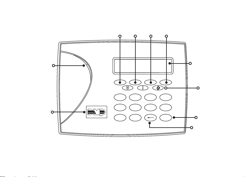
KEYPAD FEATURES
Select Keys
1 43
2
Armed/Power
LEDs
FRI 2: 52 PM
Keypad Display/
Status List
Panic Keys
Proximity
Credential Reader
and Backlit Logo
1 2 3 4
C
B
A
D
5 6 7 8
O
N
M
P
9 0 CMD
Z
Y
I
F
E
G
R
Q
S
B
L
H
K
J
X
U
W
T
V
R
E
K
T
C
N
A
E
Command
(CMD) Key
Back Arrow Key
Figure 1: Keypad Features
7000INT Series Installation and Programming Guide | Digital Monitoring Products, Inc. 2
Page 7

ENTER CHARACTERS
NUMBER PAD
1. Choose a character from the table. Use the Greek Characters table if Greek was
selected as the keypad language setting.
2. Identify the Number the character correlates with and press that number on the
number pad.
3. Identify the Select Key for the character and press that select key on the keypad.
Press that select key again for the lowercase letter (Latin characters only).
4. When the desired character displays on the keypad, return to step 1 to enter
another character or press CMD if finished.
NUMBER
1 Α Β Γ ( [ {
2 Δ Ε Ζ ) ] }
3 Η Θ Ι ! ^ ~
4 Κ Λ Μ ? “ |
5 Ν Ξ Ο / \ `
6 Π Ρ Σ & $
7 Τ Υ Φ @ %
8 Χ Ψ Ω , =
9 Space Space Space : _ ;
0 - + . ‘ * < # >
1 2 3 4
SELECT KEY
Table 1: Greek Characters
Digital Monitoring Products, Inc | 7000INT Series Installation and Programming Guide 3
NUMBER
1 A B C ( [ {
2 D E F ) ] }
3 G H I ! ^ ~
4 J K L ? “ |
5 M N O / \ `
6 P Q R & $
7 S T U @ %
8 V W X , =
9 Y Z Space : _ ;
0 - + . ‘ * < # >
1 2 3 4
Table 2: Latin Characters
SELECT KEY
Page 8
INSTALL THE KEYPAD
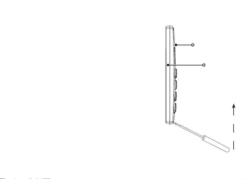
REMOVE THE COVER
1
The keypad housing is made up of two parts: the cover,
which contains the circuit board and components, and
the base.
To separate the keypad cover from the base, insert a
flathead screwdriver into one of the slots on the bottom
of the keypad and gently lift the screwdriver upward.
Repeat with the other slot. Gently separate the cover
from the base and set the cover containing the keypad
components aside. See Figure 2.
Figure 2: Separate the
Keypad Housing
7000INT Series Installation and Programming Guide | Digital Monitoring Products, Inc. 4
Cover
Base
Page 9

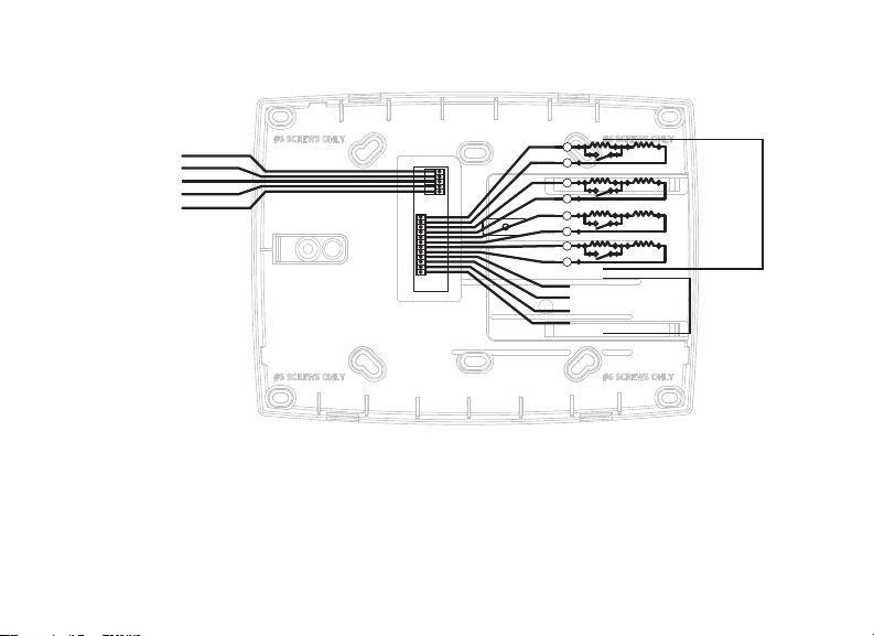
WIRE THE KEYPAD
2
Each keypad model has specific wiring assignments. All zones are supervised. The
maximum zone line impedance is 100 Ohms. Ground fault is detected at 1420 Ohms
or less. Locate the keypad model below and refer to Figure 3 to wire the keypad.
Model 7060-WINT and 7063-WINT
Use a 4-wire cable for panel keypad bus connection. See Wiring Specifications for
additional wiring information.
Model 7073-WINT
Use a 4-wire cable as needed for keypad bus and zone input connections. Use a
5-wire cable for external card reader connection. Use DMP Model 311 1k Ohm EOL
resistors on keypad zones 1-4. Connect the red wire to panel terminal 7, connect the
yellow wire to panel terminal 8, connect green wire to panel terminal 9, and connect
black wire to panel terminal 10.
Digital Monitoring Products, Inc | 7000INT Series Installation and Programming Guide 5
Page 10
Connect Reader Data 0
Connect Reader Data 1
Door Strike Normally Open
Door Strike Common
Door Strike Normally Closed
External Reader/Door Strike
7073-WINT Keypads
Black – Ground
Green – Receive Data
Yellow – Send Data
Red – Keypad Power
All Keypads
Zones
1 through 4
7073-WINT
Keypads
Note: All zones are supervised.
Maximum zoneline impedence
100 Ohms. Ground fault detected at
1420 Ohms or less.
NC
C
NO
WHT
GRN
Z4 -
Z4 +
Z3 -
Z3 +
Z2 -
Z2 +
Z1 -
Z1 +
BLK
GRN
YEL
RED
– Zone 4
– Zone 3
– Zone 2
– Zone 1
1K EOL
s
s
1K EOL
s
s
1K EOL
s
s
1K EOL
s
s
Figure 3: Keypad Back Showing Wiring Assignments
7000INT Series Installation and Programming Guide | Digital Monitoring Products, Inc. 6
Page 11

WIRE FOR ACCESS CONTROL
3
Internal Access Control Reader
The 7063-WINT and 7073-WINT keypads provide a built-in proximity card reader that
is compatible with most standard 125kHz proximity credentials. An external
13.56MHz proximity reader can be connected and will be compatible with 13.56MHz
proximity credentials. For a list of publicly supported card formats, see Public Card
Formats.
Note: Some proximity credentials are not compatible with DMP proximity
keypads. Test the intended proximity credentials with the application before
installation. DMP does not guarantee compatability with credentials not
purchased from DMP.
External Access Control Reader
To accept Wiegand data input from other external card readers, connect a 12VDC
external reader to a 7073-WINT keypad. Connect the red and black power wires
from the reader to the power wires from the panel. These connect in parallel with the
keypad power wires. Connect the reader (Data 1) wire to the white wire on the 5–wire
keypad cable. Connect the reader (Data 0) wire to the green/white wire on the 5–wire
keypad cable. See Figure 4.
Digital Monitoring Products, Inc | 7000INT Series Installation and Programming Guide 7
Page 12
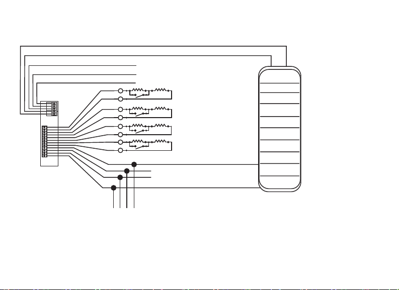
Green/White* - Connect Reader Data 0
White - Connect Reader Data 1
Orange - Door Strike Normally Open
Gray - Door Strike Common
Violet - Door Strike Normally Closed
s
NC
C
NO
WHT
GRN
Z4 -
Z4 +
Z3 -
Z3 +
Z2 -
Z2 +
Z1 -
Z1 +
BLK
GRN
YEL
RED
s
s
s
s
s
s
s
Black – Ground
Green – Receive Data
Yellow – Send Data
Red – Keypad Power
1K EOL
1K EOL
1K EOL
1K EOL
– Yellow & White
Zone 4
– Orange & White
(REX)
Zone 3
– Red & White
Zone 2
– Brown & White
(7/0 Panic)
Zone 1
External Card
Reader
*Only the green/white,
white, black, and red
wires connect to the
external card reader.
To Panel Keypad Bus
Figure 4: Access Control Wiring
7000INT Series Installation and Programming Guide | Digital Monitoring Products, Inc. 8
Page 13

WIRE THE ELECTRONIC LOCK
4
The 7073-WINT keypad provides a Form C (SPDT) relay for controlling locks
and other electronically-controlled barriers. The Form C relay draws up to 15mA
of current and the contacts are rated for 1Amp at 30VDC maximum. The three
terminals marked NOCNC allow you to connect the device wiring to the relay for
module control. Use an additional power supply to power magnetic locks and door
strikes. See Figures 5a and 5b.
WIRE THE 333 SUPPRESSOR
5
Use the included 333 suppressor with the keypad to suppress any surges caused
by energizing a magnetic lock or door strike. Install the 333 across the keypad C
(common) and NO (normally open) or NC (normally closed) terminals. If the device
being controlled by the relay is connected to the NO and C terminals, install the
suppressor on the NO and C terminals. Conversely, if the device is connected to the
NC and C terminals, install the 333 Suppressor on NC and C terminals. See Figures 5a
and 5b.
Digital Monitoring Products, Inc | 7000INT Series Installation and Programming Guide 9
Page 14
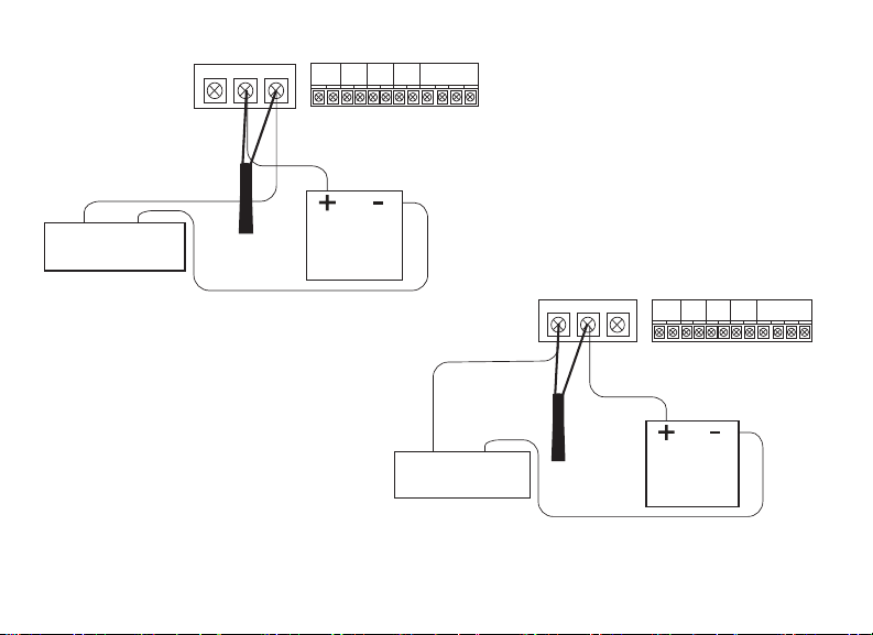
Normally Closed
C
NC
NO
Z3 +
Z4 +
Z2 -
Z3 -
Z1 -
Z2 +
BLK
Z1 +
RED
GRN
Z4 -
YEL
Magnetic Door Lock
–+
Model 333
Supressor
Figure 5a: Typical Magnetic Lock Wiring
Power Supply
–+
Door Strike Relay
Normally Open
NO
Model 333
Supressor
NCC
Z3 +
Z4 +
Z3 -
Z4 -
Power Supply
Z2 -
Z1 -
Z2 +
BLK
RED
Z1 +
GRN
YEL
Figure 5b: Typical Door Strike Wiring
7000INT Series Installation and Programming Guide | Digital Monitoring Products, Inc. 10
Page 15

MOUNT THE KEYPAD
TAMPER PROTECTION
1. Insert the included tamper puck into the base. See Figure 6.
2. Secure the tab to the wall with a #6 screw.
3. Ensure all cables are routed through the housing holes before fully mounting the
base to the wall.
4. Use #6 screws to secure the keypad base to the surface.
5. Place the keypad cover back onto the base and snap into place.
Note: All DMP keypad housings are designed to install on any 4” square box,
3-gang switch box, DMP 695 and 696 back-box, or a flat surface.
Digital Monitoring Products, Inc | 7000INT Series Installation and Programming Guide 11
Page 16

Tamper Puck
Surface and Backbox
Mounting Holes
Figure 6: Tamper Protection
Combined 4-Square
and Gang Switch Box
Mounting Holes
7000INT Series Installation and Programming Guide | Digital Monitoring Products, Inc. 12
Page 17

PROGRAM THE KEYPAD
Refer to the appropriate panel programming guide as needed. Keep in mind that
operation for some programming options is restricted to the appropriate model. To
program a keypad, access the Installer Options menu by pressing and holding the CMD
and back arrow keys at the same time for two seconds. At SET BRIGHTNESS, enter
3577 (INST) and CMD for XR150INT/XR550INT Series panels or enter 357 and CMD for
XT30INTSeries panels.
KEYPAD OPTIONS
KPD KPD
OPT DIAG STOP
Keypad Options
To program keypad options, press the select key under
KPD OPT.
CURRENT KEYPAD
ADDRESS: 1
Current Keypad Address
Set the current keypad address from 01 to 08 for XT30INT
or XR150INT Series panels, or 01 to 16 for XR550INT Series
panels. The default address is set at 01. To change the
current address, press any select key to clear the keypad
display, enter the new address, and press CMD. Do not enter
a leading zero for addresses 01 to 09.
Digital Monitoring Products, Inc | 7000INT Series Installation and Programming Guide 13
Page 18

KEYPAD MODE:
*SUP UNSUP
Keypad Mode
Keypads with programmed zones must be supervised and
cannot share an address with other keypads. Unsupervised
keypads can operate together sharing the same address, but
cannot be used when Device Fail Output has a programmed
value other than zero. To select a keypad mode, press the
select key under SUP or UNSUP. An asterisk appears next to
the selected option.
DEFAULT KPD MSG:
Default Keypad Message
Enter a custom message of up to 16characters to appear at
the top of the keypad display. Press any select key, enter a
new message, and press CMD. See Enter Characters.
ARM PANIC KEYS:
*PN EM *FI
Arm Panic Keys
Use this option to configure the select keys as two-button
panic keys. To enable or disable a panic option, press
the select key under the desired name: PN (panic), EM
(emergency), and FI (fire). Press the select key again to
disable the panic option. Once the panic option is enabled,
an asterisk displays next to the selected option(s). Press
CMD.
7000INT Series Installation and Programming Guide | Digital Monitoring Products, Inc. 14
Page 19

7/0 PANIC
ENABLE: NO
ACTIVATE ZONE 2
BYPASS? NO
7/0 Panic
Press the fourth select key to choose YES, configuring the
7and 0 keys as two-button panic keys. Select NO to disable
the option. Default is NO.
Activate Zone 2 Bypass
Select YES to activate the zone 2 bypass operation.
Selecting NO allows standard zone operation on Zone 2.
The default is NO. If the door being released by the keypad
is protected (contact installed), a programmable bypass
entry/exit timer can be provided by connecting its contact
wiring to the keypad Zone 2. When the on-board Form C
relay activates and the user opens the door connected
to Zone 2, the zone is delayed for the number of seconds
programmed in ZONE 2 BYPASS TIME allowing the user to
enter/exit during an armed period.
If Zone 2 does not restore (door closed) within the
programmed time, the keypad sounds every other second
during the last ten seconds. If Zone 2 restores prior to the
end of the programmed time, the keypad silences. If the
zone does not restore before the programmed time, the
keypad ends the bypass and indicates the open or short
zone condition to the panel.
Digital Monitoring Products, Inc | 7000INT Series Installation and Programming Guide 15
Page 20

ZONE 2 BYPASS
TIME: 40
Zone 2 Bypass Time
Enter the number of bypass seconds to elapse before the
bypass timer expires. Range is from 20-250 seconds. Press
any select key to clear the keypad display and enter the
number of seconds. Default is 40 seconds.
RELOCK ZONE 2
CHANGE: NO YES
Relock on Zone 2 Change
Select NO (default) to leave the relay on when Zone 2
changes to an open or short condition during bypass.
Select YES to turn the relay o when Zone 2 changes to
open or short during bypass.
ACTIVATE ZONE 3
EXIT: NO YES
Activate Zone 3 Exit
Select YES to activate the Zone3 Request to Exit (REX)
option. Select NO (default) to allow standard zone operation
on Zone3. Connect a motion sensing device or a mechanical
switch to Zone 3 to provide REX capability to the system.
When Zone 3 shorts, the on-board Form C relay activates for
the programmed number of seconds (see Zone 3 REX Strike
Time). During this time, the user can open the protected
door to start the programmed Zone 2 bypass entry/exit
timer. After the programmed number of seconds, the relay
restores the door to its locked state.
7000INT Series Installation and Programming Guide | Digital Monitoring Products, Inc. 16
Page 21

ZONE 3 REX STRIKE
TIME: 5
ALL?: NO YES
DELAY: 2
The keypad provides a bypass-only option for REX on
Zone3. When Zone 3 opens from a normal state, only a
bypass occurs: the on-board relay does not activate. This
bypass-only option uses two methods of REX. The first REX
device provides the programmed bypass entry/exit timer.
The second REX unlocks the door.
Zone 3 REX Strike Time
Enter the number of REX seconds to elapse. Range is
5-250seconds. Press any select key to clear the keypad
display and enter the number of seconds. The default is 5.
Arming/Disarming Wait Time
Select the number of seconds (0-9) the keypad should
wait to arm and disarm when an Area system displays
ALL?NOYES or a H/S/A system waits during arming only.
If NO or YES, or HOME, SLEEP, or AWAY is not manually
selected before the delay expires, the keypad automatically
selects YES or AWAY. Select zero (0) to disable this feature.
The delay also occurs when a credential is presented for
arming the H/S/A system. Default is 2.
Digital Monitoring Products, Inc | 7000INT Series Installation and Programming Guide 17
Page 22

CUSTOM CARD FORMAT (XR150INT/XR550INT ONLY)
ANY CARD FORMAT
NO YES
CARD FORMATS
FORMAT NO: -
FORMAT NAME
*UNUSED*
7000INT Series Installation and Programming Guide | Digital Monitoring Products, Inc. 18
Any Card Format
Select YES to allow all card reads to activate the door strike
relay. The door strike relay is activated for the length of time
programmed in ZN 3 REX TIME. No user code information is
sent to the panel. Default is NO.
Card Formats
Select the slot number (1-7) that you would like to program a
custom non-DMP card format into. Select 8 if you would like
to program a DMP card format. See Public Card Formats for
some of the card formats that can be used with the keypad.
Other private or custom formats may also be compatible.
Please contact the credential supplier or manufacturer for
the bit structure. Press CMD to advance.
Format Name
Press any select key to rename the card format. Press CMD
to save and advance.
Page 23

WEIGAND CODE
Position = 0
Position = 25
LENGTH: 26
Wiegand Code Length
When using a custom credential, enter the total number of
bits to be received in Wiegand code including parity bits.
Press any select key to enter a number between 1-255 to
equal the number of bits. Default is 26 bits.
An access card contains data bits for a site code, user code,
and start/stop/parity bits. The starting position, location, and
code length must be determined and programmed into the
keypad. See Figure7.
01110101101101010001100111
First Bit
Received
Site Code
Position = 1
Length = 8
User Code
Position = 9
Length = 16
Last Bit
Received
In this example the Wiegand Code Length = 26 bits.
Figure 7: Wiegand Data Stream Bit
Digital Monitoring Products, Inc | 7000INT Series Installation and Programming Guide 19
Location
Page 24

SITE CODE
LEN:
LEN:
POS: 1
Site Code Position and Length
Enter the site code start position and length in the data
8
string. Press select key 2 to clear the site code start position
and enter a number between 0-255. Press CMD to save.
Default is 1.
Press select key 4 to clear the site code length and enter a
number between 1-24. Press CMD to save. Default is 8.
USER CODE
POS: 9
User Code Position and Length
Define the user code start bit position and length. Press
16
select key 2 to clear the user code position and enter a
number between 0-255. Press CMD to save. Default is 9.
Press select key 4 to clear the user code length and enter
a number between 16-64. Press CMD to save. The default is
the DMP value of 16.
REQUIRE SITE
CODE: NO YES
Require Site Code
Press the select key under YES to use a site code and
press CMD to view the site code entry display. Press NO to
advance to NO OF USER CODE DIGITS. Default is NO.
In addition to user code verification, door access is only
granted when any one site code programmed at the
SITE CODE option matches the site code received in the
Wiegand string.
7000INT Series Installation and Programming Guide | Digital Monitoring Products, Inc. 20
Page 25

SITE CODE 1:
NO OF USER CODE
DIGITS: 5
NO COMM WITH PNL
OFF SITE ANY ON
Site Code
You can program up to eight 8-digit site codes. The site code
range is 0-16,777,214.
In the keypad display, enter site code 1 and press CMD. The
display will ask for site code 2 followed by site code 3 and
so on. When you have selected the site code you want to
change, press CMD.
Number of User Code Digits
The keypad recognizes user codes from 4-12 digits in length.
Press any select key to clear the keypad display and enter
the user code digit length being used by the panel. Default
is 5. For an XR150INT/XR550INT area type, use 4-10digits
(typically 5). For all other systems and panels, use 4 digits.
No Communication with Panel
Define the relay action when communication with the panel
has not occurred for 5seconds. Default is OFF. Press any
select key to change the default relay action:
Press the first select key to choose OFF (Relay Always
O). The relay does not turn on when any Wiegand string
is received. OFF does not aect any REX operation. If
communication is lost during a door strike, the relay remains
on for the door strike duration but turns o at the end of the
door strike timer.
Digital Monitoring Products, Inc | 7000INT Series Installation and Programming Guide 21
Page 26

Press the second select key to choose SITE (Accept Site
Code). Door access is granted when the Wiegand site
code string received matches any site code programmed
at SITECODE DISPLAY. Refer to REQUIRE SITE CODE for
more information.
Press the third select key to choose ANY (Any Wiegand
Read). Access is granted when any Wiegand string is
received.
Press the fourth select key to choose ON (Relay Always On).
The relay is always on.
Press CMD to display the next action.
NO COMM WITH PNL
LAST
7000INT Series Installation and Programming Guide | Digital Monitoring Products, Inc. 22
Press the first select key to choose LAST (Keep Last State).
The relay remains in the same state and does not change
when communication is lost.
Page 27

KYPD LANGUAGE:
LANG: ENGLSH
KYPD LANGUAGE:
ENG SPN FRN DUT
KYPD LANGUAGE:
EΛΛ CZK
Keypad Language
Define the keypad’s language. Default is ENGLSH.
Press any select key to change the language options.
Press select key 1 to select English. Press select key 2 to
select Spanish. Press select key 3 to select French. Press
select key 4 to select Dutch.
Press CMD to advance the language options.
Press select key 1 to select Greek. Press select key 2 to select
Czech.
Digital Monitoring Products, Inc | 7000INT Series Installation and Programming Guide 23
Page 28

ADDITIONAL PROGRAMMING
Users can manually enter their user code into the keypad which then verifies the user
code and its authority with the panel. The 7073-WINT activates the on-board Form C relay
releasing a door strike or magnetic lock. To provide added flexibility, the keypad allows
connection of an external Wiegand output compatible reader.
Proximity Credential Compatibility
DMP keypads with internal proximity readers are compatible with most standard 125Khz
proximity credentials. An external 13.56MHz proximity reader can be connected and will
be compatible with 13.56MHz proximity credentials. For a list of publicly supported card
formats, see Public Card Formats.
Note: Some proximity credentials are not compatible with DMP proximity keypads.
Test the intended proximity credentials with the application before installation. DMP
does not guarantee compatability with credentials not purchased from DMP.
Program a Credential
1. Access the User Menu by pressing CMD until MENU? NO YES displays. Choose
YES, and present your proximity credential to the reader or manually enter your
user code at the keypad.
2. Press CMD until USER CODES? displays.
3. Press any select key. Choose ADD.
4. At ENTER CODE: -, present the credential to the reader. The keypad works by
reading the user code from the data string sent by the access control reader.
7000INT Series Installation and Programming Guide | Digital Monitoring Products, Inc. 24
Page 29

TEST THE KEYPAD
Test the keypad to ensure alarm backlighting, individual shortcut keys, and any
programmed zones work. To begin testing, access the Installer Options menu. Hold down
the back arrow and CMD keys at the same time until SET BRIGHTNESS displays. Enter
3577 and press CMD.
KPD KPD
OPT DIAG STOP
PRESS KEY TO
TEST
Keypad Diagnostics
Press the select key under KPD DIAG. The keypad lights all
display segments and illuminates the keyboard in red. The
display backlighting then changes to green. The keypad
alternates between these two states for approximately two
minutes. Press CMD at any time to begin testing individual
keys.
Test Individual Keys
The display changes to PRESS KEY TO TEST. This option
tests each key on the keyboard to ensure it is operating
properly. Press and hold each key for two seconds. The key
number being held appears in the display. Verify the correct
number displays before testing the next key.
Digital Monitoring Products, Inc | 7000INT Series Installation and Programming Guide 25
Page 30

Z1 OPEN Z2 OPEN
Z3 OPEN Z4 OPEN
Zone Test
This option allows the keypads to display the current
electrical status of the four protection zones. The status is
shown as OPEN, SHRT, or OKAY . The zone test displays on
the other keypads but is not operational.
INPUT WIEGAND
Test the Credential Reader
This option tests the internal and external reader input from
proximity credentials. The display shows OK AY each time a
good proximity read is received.
7000INT Series Installation and Programming Guide | Digital Monitoring Products, Inc. 26
Page 31

END USER TRAINING
This section contains instructions on how users can arm and disarm their system, use
access control, and the entry delay feature, if programmed. All of the examples displayed
assume that CLOSING CODE is YES in panel programming.
ARM AND DISARM THE SYSTEM
Area System Type
1. Press CMD until the keypad displays ARM DISARM.
2. Press the select key under the preferred option.
3. If arming, the keypad displays ALL? NO YES. Select NO to arm individual areas.
Select YES to arm all areas. If disarming, the keypad displays ENTER CODE: -. The
user can either enter their user code or present their credential to the proximity
reader. Once validated by the system, all areas assigned to that code or credential
disarm automatically
All/Perimeter System Type
Press CMD until ARM DISARM displays. If arming, press ARM. Select ALL to arm all
areas or PERIM to arm only the perimeter. At ENTER CODE: -, enter a user code at the
keypad or present a credential to the proximity reader. If disarming, select DISARM. At
ENTER CODE: -, enter a user code at the keypad or present a credential to the proximity
reader.
Digital Monitoring Products, Inc | 7000INT Series Installation and Programming Guide 27
Page 32

Home/Sleep/Away System Type
Press CMD until ARM DISARM displays. If arming, present a credential to the proximity
reader. Once the card is validated, HOME SLEEP AWAY displays. Select HOME to arm the
perimeter, select SLEEP to arm everything except the bedroom areas, or select AWAY to
arm all areas. If a selection is not made, all areas will automatically arm AWAY. If disarming,
present a credential to the proximity reader. Once the card is validated, all areas are
disarmed and the keypad displays ALL SYSTEM OFF.
USE ACCESS CONTROL
Access an Area Using the Door Strike
If the Door Strike Relay was wired and programmed at
the keypad, present a credential to the proximity reader.
Once the system validates the card, the Door Strike Relay
activates. See Figure 8.
Use Entry Delay When Disarming
If an Entry Delay was programmed at the keypad for
area system types, the keypad sounds an entry tone
and displays ENTER CODE: - if an access door was
accessed. Present a credential to the proximity reader.
Once validated, the system disarms all areas accessible by
the credential and activates the Door Strike Relay. Area
systems provide a delay to allow selected areas only to be
disarmed. See Figure 9.
7000INT Series Installation and Programming Guide | Digital Monitoring Products, Inc. 28
Figure 8: Present Access Card
Figure 9: Entry Delay
Page 33

WIRING SPECIFICATIONS
When planning a keypad bus installation, keep in mind the following specifications:
• DMP recommends using 18 or 22 AWG unshielded wire for all keypad and LX-Bus
circuits. Do not use twisted pair or shielded wire for LX-Bus and keypad bus data
circuits. To maintain auxiliary power integrity when using 22-gauge wire, do not
exceed 500 feet. When using 18-gauge wire, do not exceed 1,000 feet. Install an
additional power supply to increase the wire length or add devices.
• Maximum distance for any one circuit (length of wire) is 2,500 feet regardless of the
wire gauge. This distance can be in the form of one long wire run or multiple branches
with all wiring totaling no more than 2,500 feet. As wire distance from the panel
increases, DC voltage on the wire decreases.
• Maximum number of devices per 2,500 feet circuit is 40.
Note: Each panel allows a specific number of supervised keypads. Add
additional keypads in the unsupervised mode. Refer to the panel installation
guide for the specific number of supervised keypads allowed.
• Maximum voltage drop between the panel (or auxiliary power supply) and any device
is 2VDC. If the voltage at any device is less than the required level, add an auxiliary
power supply at the end of the circuit. When voltage is too low, the devices cannot
operate properly.
Digital Monitoring Products, Inc | 7000INT Series Installation and Programming Guide 29
Page 34

KEYPAD SPECIFICATIONS
INTERNAL
DOOR
STRIKE
RELAY
MODEL
NORMAL/STAND-
BY CURRENT
ALARM CURRENT
FOUR
ZONES
INTERNAL
PROX
READER
WIEGAND
INPUT
7060INT 72mA 87mA
7063INT 85mA 100mA X
7073INT
85mA+1.6mA
per active zone
100mA+2mA
per active zone
X X X X
Table 3: Keypad Specifications
7000INT Series Installation and Programming Guide | Digital Monitoring Products, Inc. 30
Page 35

PUBLIC CARD FORMATS
CARD
FORMAT
H10301 26 BIT 26 1 8 9 16 5
H10302 37 BIT
W/FAC
H10304 37 BIT
W/O FA C
FARPOINTE
39 BIT
CORPORATE
1000 35 BIT
CORPORATE
1000 48 BIT
WIEGAND
CODE
LENGTH
37 1 16 17 19 6
37 0 0 1 35 12
39 1 17 18 20 7
35 2 12 14 20 6
48 2 22 24 23 7
Digital Monitoring Products, Inc | 7000INT Series Installation and Programming Guide 31
SITE
CODE
POSITION
SITE
CODE
LENGTH
USER
CODE
POSITION
USER
CODE
LENGTH
USER
CODE
DIGITS
Page 36

READERS AND CREDENTIALS
125 KHZ PROXIMITY READERS
125 KHZ PROXIMITY CREDENTIALS
P-300 CASCADE PROXIMITY
READER
P-500 ALPS PROXIMITY READER
P-640 PATAGONIA PROXIMITY
READER WITH KEYPAD
MP-5365 MINIPROX™ PROXIMITY
READER
MX-5375 MAXIPROX® PROXIMITY
READER
PP-6005B PROXPOINT® PLUS
PROXIMITY READER
PP-5355 PROXPRO PROXIMITY
READER WITH KEYPAD
PR-5455 PROXPRO® II PROXIMITY
READER
TL-5395 THINLINE II® PROXIMITY
READER
7000INT Series Installation and Programming Guide | Digital Monitoring Products, Inc. 32
PSC-1 STANDARD LIGHT
PROXIMITY CARD
PSK-3 PROXIMITY KEY
RING TAG
PSM-2P ISO IMAGEABLE
PROXIMITY CARD
1306 PROX PATCH™
1326 PROXCARD II®
CARD
1346 PROXKEY III®
ACCESS DEVICE
1351 PROXPASS®
1386 ISOPROX II® CARD
Page 37

13.56 MHZ SMARTCARD READERS
13.56 MHZ SMARTCARD CREDENTIALS
DELTA3 FARPOINTE SMARTCARD
READER
DELTA5 FARPOINTE SMARTCARD
READER
DELTA5.3 FARPOINTE SMARTCARD
READER
DELTA6.4 FARPOINTE SMARTCARD
READER
Digital Monitoring Products, Inc | 7000INT Series Installation and Programming Guide 33
DC1-1 FARPOINTE CLAMSHELL
SMARTCARD
DM1-3 FARPOINTE IMAGEABLE
SMARTCARD
DE2 FARPOINTE MIFARE®
DESFIRE® EV1
SMARTCARD
DK1-3 FARPOINTE KEY FOB
SMARTCARD
Page 38

COMPLIANCE SPECIFICATIONS
Specifications
• Operating Voltage 12VDC
• Dimensions 17.78 W x 13.335 H x 1.27 D cm
• Weight .43kg
• Tamper Security Type B Fixed
• Security Grade 3
• Environment Class II
• Operating Temp. 0°C - 49°C
• Relative Humidity 80%
Compatibility
• XT30INT Series Panels
• XR150INT/XR550INT Series Panels
What Is Included?
• One LCD Keypad
• One Model 333 Suppressor
Accessories
695 or 696 Keypad Backbox, 777 protective keypad cover
7000INT Series Installation and Programming Guide | Digital Monitoring Products, Inc. 34
Page 39

INTERNATIONAL CERTIFICATIONS
Security Grade 3
Environment Class II
Intertek (ETL) Listed
EN 50130-4:2011+A1:2014 Alarm systems. Electromagnetic compatibility. Product
family standard: Immunity requirements for components
of fire, intruder, hold up, CCTV, access control and social
alarm systems.
EN 50130-5:2011 Alarm systems. Environmental test methods.
EN 50131-1 2006+A1:2009 Alarm systems. Intrusion and hold-up systems. System
requirements.
EN 50131-3:2009 Alarm systems. Intrusion and hold-up systems. Control
and indicating equipment.
EN 60839-11-1:2013 Alarm and electronic security systems. Electronic access
control systems. System and components requirements.
EN 61000-3-2:2006+A1+A2 Electronic compatibility (EMC)–Part 3-2: Limits – Limits for
harmonic current emissions.
Digital Monitoring Products, Inc | 7000INT Series Installation and Programming Guide 35
Page 40

EN 61000-3-3:2013 Electromagnetic compatibility (EMC) – Part 3-3: Limits
– Limitation of voltage changes, voltage fluctuations
and flicker in public low-voltage supply systems, for
equipments with rated current <16 A per phase and not
subject to conditional connection.
EN 61000-6-4:2007 Emission standard for industrial environments.
Information furnished is believed to be accurate and reliable.
This information is subject to change without notice.
7000INT Series Installation and Programming Guide | Digital Monitoring Products, Inc. 36
Page 41

Page 42

Page 43

Page 44

LT-0883INT 19081 1.01 © 2019 Digital Monitoring Products, Inc.
 Loading...