

DMP Electronics eBox-2300, VESA PC eBox-2300, VESA PC eBox-2300-H, VESA PC eBox-2300-M, VESA PC eBox-2300-JSK. User Manual
Page 1
DMP Group
Page 2

eBox-2300 i
COPYRIGHT
The information in this manual is subject to change without notice for continuous
improvement in the product. All rights are reserved. The manufacturer assumes no
responsibility for any inaccuracies that may contain in this document, and makes no
commitment to update or to keep current information contain in this manual.
No part of this manual may be reproduced, copied, translated or transmitted, in whole or
in part, in any form or by any means without the prior written permission of the DMP
Electronics Inc.
©Copyright 2006 DMP Electronics Inc.
Manual No. IUMEBOX2300-01 Ver.0.1
Revised Date: Sep, 2006
1st Issued Date: Sep 01, 2006
SPECIAL NOTICE TO USERS
DMP Electronics Inc. provides no warranty with regard to this manual, the software, or
other information contained herein and hereby expressly disclaims any implied
warranties of merchantability or fitness for any particular purpose with regard to this
manual, the software, or such other information. In no event shall DMP Electronics be
liable for any incidental, consequential, or special damages, whether based on tort,
contract, or otherwise, arising out of or in connection with this manual, the software, or
other information contained herein or the use thereof.
DMP Electronics reserves the right to make any modification to this manual or the
information contained herein at any time without notice. The software described herein
is governed by the terms of a separated user license agreement or label sticker.
This product contains software owned by DM&P and licensed by third parties. Use of
such software is subject to the terms and conditions of license agreements enclosed
with this product. Software specifications are subject to change without notice and may
not necessarily be identical to current retail versions.
Updates and additions to software may require an additional charge. Subscription to
online service providers may require a fee and credit card information. Financial
services may require prior arrangements with participating financial institution.
Page 3

eBox-2300 ii
TRADEMARKS ACKNOWLEDGMENT
eBox-2300 is the registered trademarks of DMP Electronics Inc.
Microsoft®, Windows® and AMI are registered trademarks of Microsoft Corporation and
American Megatrends, Inc. in the United States and/or other countries respectively.
Other brand names, product names or trade names appearing in this document are the
properties and registered trademarks of their respective owners. All names mentioned
herewith are served for identification purpose only.
OWNER’S RECORD
The serial number of this product is located at the rear panel of your eBox-2300 series.
Refer to the model and serial number when you contact your nearest dealer or DMP
offices for services. The Model No. of this product is also indicated on the product label
of your gift box as: eBox-2300, eBox-2300-H, eBox-2300-M and eBox-2300-JSK.
Page 4

eBox-2300 iii
SAFETY INFORMATION
WARNING
Do not expose your VESA PC to rain or moisture, in order to prevent
shock and fire hazard.
Never install your VESA PC in wet locations.
Do not open the cabinet to avoid electrical shock. Refer to your nearest
dealer for qualified personnel servicing.
Never touch un-insulated terminals or wire unless your power adaptor and
display monitor are disconnected.
Locate your VESA PC as close as possible to the socket outline for easy
access and to avoid force caused by entangling of your arms with
surrounding cables from the VESA PC.
When using eBox-2300, avoid using or installing the modem to the serial
port during a storm or a lightning.
Do not use the modem or a telephone to report a gas leak in the vicinity of
the leak.
USB connectors are not supplied with Limited Power Sources.
DO NOT ATTEMPT TO OPEN OR TO DISASSEMBLE THE CHASSIS
(ENCASING) OF THIS PRODUCT. PLEASE CONTACT YOUR
NEAREST DEALER FOR SERVICING FROM QUALIFIED TECHNICIAN
.
Page 5

eBox-2300 iv
REGULATORY
FCC CLASS A NOTE
This equipment has been tested and found to comply with the limits for a Class A digital
device, pursuant to Part 15 of the FCC Rules. These limits are designed to provide
reasonable protection against harmful interference when the equipment is operated in a
commercial environment. This equipment generates, uses and can radiate radio
frequency energy and, if not installed and used in accordance with the instruction
manual, may cause harmful interference in which case the user will be required to
correct the interference at his own expense. Testing was done with shielded cables.
Therefore, in order to comply with the FCC regulations, you must use shielded cables
with your installation.
WARNING
This product complies with EN55022 class A. In a domestic environment this product
may cause radio interference in which case the user may be required to take adequate
measures.
Changes or modifications to this unit not expressly approved by the party responsible for
compliance could void the user’s authority to operate the equipment.
This device complies with Part 15 of the FCC rules. Operation is subject to the following
two conditions: (1) this device may not cause harmful interference, and (2) this device
must accept any interference received, including interference that may cause undesired
operation.
This digital apparatus does not exceed the Class A limits for radio noise emissions from
digital apparatus as set out in the interference - causing equipment standard entitled
“Digital Apparatus”, ICES-003 of the Department of Communications.
MANUFACTURER’S DECLARATION OF CONFORMITY
This equipment has been tested and found to comply with the requirements of European
Community Council Directives 89/336/EEC and 73/23/EEC relating to electromagnetic
compatibility and product safety respectively.
ATTENTION
This product has been designed and certified to comply with certain regulatory
requirements pertaining to Information Technology Equipment. This product has not
been designed for use as a medical device. Without limitation of the foregoing, this
product is not intended and has not been certified for use in a hospital or clinical
environment to diagnose, treat, or monitor patients under medical supervision, and is
not intended and has not been certified to make physical or electrical contact with
patients, nor to transfer energy to or from patients and/or to detect such energy transfer
to or from patients.
Page 6

eBox-2300 v
PURCHASE AGREEMENT
PURPOSE:
In accordance to the general commercial conduct of Trust and Fair Trade, herewith
below is the agreement for the protection for both parties, DMP and Users in pursuant of
trading.
PRODUCT DESCRIPTION:
With this product, herewith also known as eBox-2300, which is a simplified & an
economical design of an embedded VESA PC for Special Purpose Personal Computing.
The basic specification of this product comprises of the x86 technology design, and with
onboard 128MB System memory, Display, USB, Keyboard, PS2 Mouse, LAN, and
Audio Interfaces.
DISTRIBUTION CONVENTION:
1. This Product includes a gift box, an inner case, a PC, a Power adaptor, User’s
Manual, Utilities & Drivers CD, and IDE cable (standard eBox-2300 configuration
do not have the IDE cable). Upon receiving this product, kindly please refer to the
User’ Manual to check for the contents and appearance of this product; contact
immediately your nearest dealer or DMP office for any defective or missing parts.
The supplier will not be responsible for any reported discrepancy thereafter the
expiration period of 3-days from the date of purchase.
2. In consideration of transportation and the cost of storage, the supplier provides to
the distributors a warranty of 12-months. This warranty covers the failure caused
by hardware breakdown (excluding hard drives), but does not cover the act of
misuse and mishandling.
3. The supplier will not accept unknown post, therefore if you wish to repair or to
return your goods – kindly please contact your nearest dealer to make your
declaration, and at the same time, apply for a RMA number (RMA stands for
Return Merchandise Authorization – please see the RMA form and fill-up for
authorization).
4. The freight for return goods for repair will follow the International customary
practice and convention: Both parties is to pay for freight of one shipment each.
The shipper is required to prepaid the freight from the place of origin (This means
that the returnee (user) covers the freight for return goods, while the Supplier
covers the freight for goods after the repair).
5. Obsolete warranty is referred to as: (1) Expiration of warranty or (2) Damage due
to misuse within warranty. The Supplier will be taken into consideration of the
circumstances, to provide repair service with charges expense for obsolete
warranty. This expense includes the cost of material and the cost of labor.
NOTE:
If there is other particular issue not listed in the above conditions, both parties agreed to
follow the General Law of Commerce with fair and reasonable discussion in handling
and resolving the argument.
Page 7

eBox-2300 vi
Table of Contents
CHAPTERS – HEADING PAGE NO.
0
– UNPACKING YOUR EMBEDBOX........................................................ 1
`
PACKING LIST .............................................................................1
`
CHECK BEFORE USE ................................................................... 1
1
– PREFACE ...................................................................................... 2
2
– eBOX-2300 OVERVIEW .................................................................. 3
3
– EMBEDDED CPU BOARD ................................................................4
`
SYSTEM SPECIFICATION .............................................................. 4
4
– PERIPHERALS .................................................................................5
`
CONNECTING THE POWER ADAPTOR ............................................ 5
`
CONNECTING THE MONITOR ......................................................... 5
`
CONNECTING THE USB ............................................................... 6
`
CONNECTING USB, SPEAKER/EARPHONE & WEB ........................ 6
`
CONNECTING THE KEYBOARD AND MOUSE ...................................7
`
CONNECTING PRINTER PORT ........................................................7
5
– BIOS............................................................................................. 8
`
RECONFIGURING eBox-2300 ...................................................... 8
6
– TECHNICAL SPECIFICATION ............................................................. 9
7
– TAKING CARE YOUR VESA PC ..................................................... 10
`
STORING................................................................................... 10
`
USING CABLES FOR CONNECTION ............................................... 11
`
CLEANING YOUR VESA PC ....................................................... 11
8
– TROUBLESHOOTING....................................................................... 12
`
TROUBLESHOOTING YOUR EMBEDBOX ....................................... 12
`
VESA PC DOES NOT START....................................................... 12
`
BIOS ERROR MESSAGE............................................................. 12
`
“OPERATING SYSTEM NOT FOUND”............................................ 13
A
PPENDIX : ONBOARDCONNECTORS SUMMARY.................................... 14
Page 8

eBox-2300 vii
` SUMMARY TABLE FOR CPU BOARD............................................ 14
`
FRONT CONNECTORS OUTLINE FOR eBOX-2300......................... 14
`
REAR CONNECTORS OUTLINE FOR eBOX-2300.......................... 15
`
PIN ASSIGNMENTS..................................................................... 16
W
ARRANTY : TERMS AND CONDITION................................................... 18
1
WARRANTY .............................................................................. 18
2
SERVICE AND SUPPORT .............................................................18
3
RETURN MERCHANDISE AUTHORIZATION (RMA) POLICY ............. 18
4
SHIPPING POLICY ...................................................................... 18
Page 9
eBox-2300 1
UNPACKING YOUR EMBEDBOX
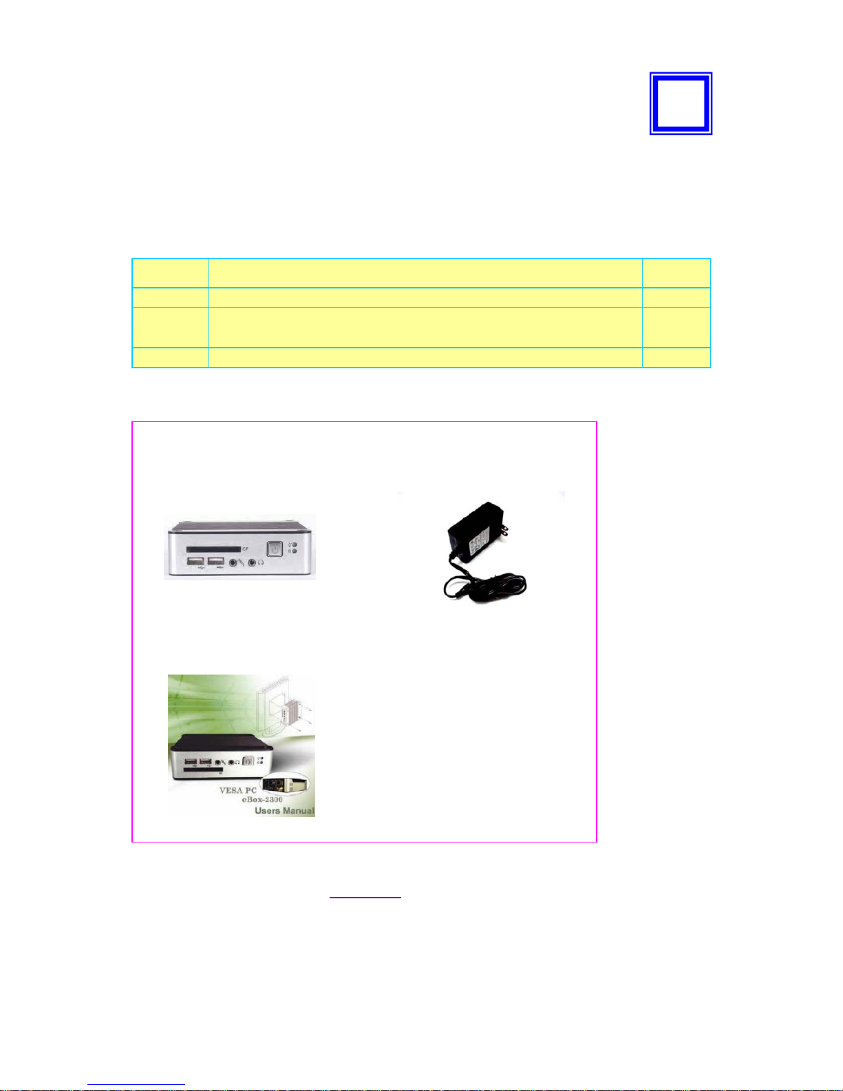
Congratulation! You have just acquired eBox-2300, the world’s smallest and
compact PC (See Figure 1), please check the following items:
PACKING LIST FOR eBOX-2300 SERIES
Item Description Q’ty
c
eBox-2300 VEA PC
1
d
Max. 15-watts External Power Adaptor, Vin: 100~240VAC • 60/50Hz,
1.0A / Vout: +5.0~5.25VDC @ 3A max.
1
e
User’s Manual
1
* Note: The accessories are subject to change without immediate notice.
CHECK BEFORE USE
c eBox-2300
VESA PC
d AC Power Adaptor
e User’s manual
0
Figure 1
Page 10

eBox-2300 2
PREFACE
eBox-2300: VESA PC
eBox-2300 is a revolutionary device, that is especially designed for limited physical
space and temperature concerns. No matter you are in a jammed office, a crowded
place, or public transportation, it can be easily integrated with a VESA LCD to bring you
VESA PC access at any time.
It can attach to any VESA mounting fixture, allowing it to be securely mounted onto
desks, walls, or buildings, and thereby optimizes your work area. It can also attach
directly to any size LCD for a mobile system for the use at trade shows, presentations,
promotions, etc. Unlike traditional portable laptop design, the VESA PC can be used
with a large size LCD. Furthermore, with FANLESS design, eBox-2300 is ideal to be
used in the environment where temperature demand is critical.
So, if you are looking for a device that is able to provide you with more mobility & space
but at the same time uses less power consumption, then eBox-2300 will be surely meet
your need.
The VESA® FDMI™ Standard defines mounting interfaces, hole patterns and
associated cable/power supply locations for LCD monitors, plasma displays and other
flat panel devices. eBox-2300 is designed to fit this standard to make monitor
attachment quick and easy.
1
Page 11

eBox-2300 3
eBOX-2300 OVERVIEW
Front Panel
Power LED
The power LED lights up, when system is
turn on.
HDD LED
The HDD LED flashes when the system is
working. Please do not turn off the system
when HDD start running
Power Switch
Depress switch to turn on & turn off the
systems.
CF Slot
For connection to Device with CF Card
and Micro Driver.
Audio Line Out
Audio Mic InPower Switch
USB port
For connection to devices with USB
interface(HDD, CD/DVD-ROM, Memory
Stick, etc.)
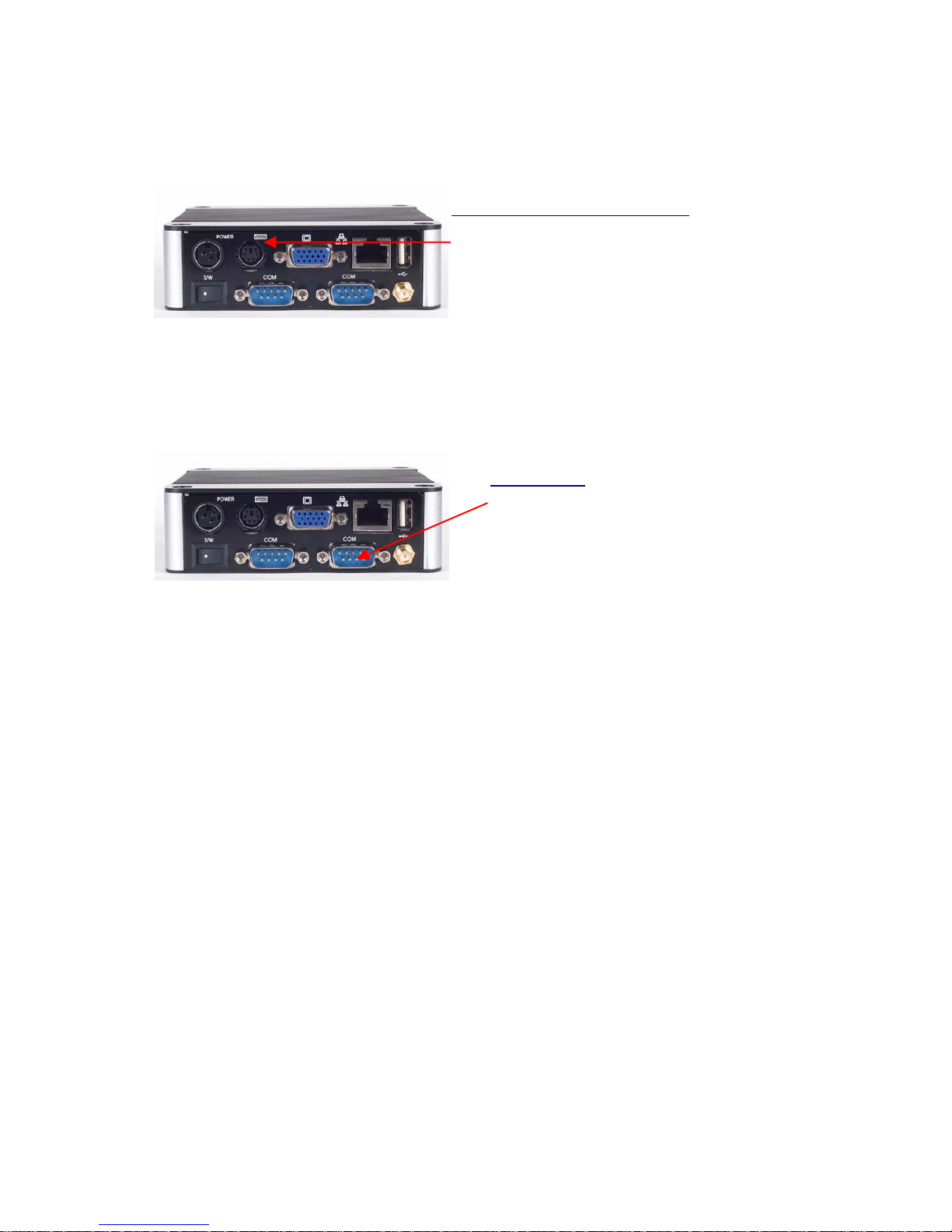
Back Panel
` Power switch
` DC Power Jack (3-pin)
` PS/2 Keyboard or Mouse (6-pin)
` VGA
` RJ-45 LAN Jack
` Serial Port (option for eBox-2300-
JSK)
` USB Port
` Wireless Antenna connector
(optional)
2
Page 12

eBox-2300 4
About Embedded CPU Board
SYSTEM SPECIFICATION
CPU
Vortex86 SoC (System on Chip)
Main Memory
128MB SDRAM
BIOS
AMI BIOS
VGA
AGP Rev.2.0 Compliant
Resolution up to 1,280x1,024 High Colors
Audio
AC97 CODEC, Fully Compliant with
AC97v2.1
LAN
Realtek 8100B, 10/100Mbps Ethernet
Interface
Keyboard and Mouse
PS/2 Keyboard and Mouse
On-Board IDE
Enhanced IDE interface, 44-pin box
header x 1
Peripheral
1. USB V1.1 ports x 3
2. Serial port x2(This function only
available for eBox-2300-JSK)
3. Audio(Mic-in, Line-in)
4. Type I/II CF Slot (Support Micro Driver)
Dimension & Weight
115 x 115 x 35 mm / 505g
Operating System
Suitable for –
Windows CE.NET
Windows XP Embedded
Linux
3
Page 13

eBox-2300 5
PERIPHERALS
CONNECTING THE POWER ADAPTOR
Power Adaptor
To use your VESA PC immediately, take
and use the supplied AC adapter as a
power source. See the left diagram for
visual connection.
Connect the DC power jack of the power
adaptor to the DC Input jack of eBox-
2300.
Turning ON Your VESA PC
Press the power button as indicated on
the figure on your left-side, the system will
start automatically.
CONNECTING THE MONITOR
VGA Connection
Depending on your choice of viewing,
select a conventional CRT or the LCD
VGA monitor.
Make your connection by following the
reference diagram from the VGA cable of
your cable to the 15-pin D-Sub VGA port
of eBox-2300.
4
Page 14

eBox-2300 6
PERIPHERALS
CONNECTING THE USB
eBox-2300 provides USB port (Two in front & one at the back).
Front cabinet
USB Ports
The second USB port is available for
connection to USB devices.
Speaker/Earphone
eBox-2300 supports Input/Output device
for speaker and Microphone
CONNECTING SPEAKER/EARPHONE AND LAN
Connecting to LAN
There is an available RJ-45 LAN jack for
connection to the hub of your intranet;
and via your server for internet service
(see diagram for RJ-45 LAN jack).
Page 15
eBox-2300 7
CONNECTING THE KEYBOARD AND MOUSE
PS/2 Keyboard or Mouse (6-pin)
The PS/2 Port is available for connect
Keyboard or Mouse.
C
ONNECTING SERIAL PORT
Serial Ports
The serial port is usually connected to a
serial device like modem (option for eBox2300-JSK
Page 16

eBox-2300 8
BIOS
RECONFIGURING eBox-2300
1. Take note that AMI BIOS is used in the eBox-2300 VESA PC. To reconfigure the
VESA PC, depress or hit the <Del> key to enter your BIOS setup main menu.
2. Select from the menu, the desired setup for change.
3. Press <Esc> to go back to main menu.
4. Move your cursor to “Save Settings and Exit”, press “Y” to save the changes that
you just made. eBox-2300 will restart accordingly to your new setup.
5
Page 17

eBox-2300 9
TECHNICAL SPECIFICATION
Features
Description
CPU Vortex86 SoC
BIOS AMI BIOS
System Memory Onboard 128MB SD-RAM
Expansion 1x Mini-PCI connector (option for eBox-2300-M)
I/O
MIO 1 x EIDE (44-pin)
2 x RS-232**, 1x PS/2 for K/B or Mouse
1 x RJ-45 Ethernet Connector
1 x Type I/II Compact Flash slot
USB 3 x USB 1.1 Ports (two in front)
Display
Display Memory 8MB shared system memory
Resolution Up to 1280 x 1024
Audio
AC97 2.1 (Codec) AC97 V2.1 Codec
Audio Interface Line out, Mic in
Ethernet
Chipset Realtek 8100B
Remote Boot ROM Built-in boot ROM function
Mechanical &Environment
Power Requirement+ 5V~5.25V @ 3A
Operating Temperature0 0 ~ 60oC
Operating Humidity 0% - 90% relative humidity, non-condensing
Size (W x H x D)
115 x 115 x 35 mm
Weight 505g
Certification CE,FCC
6
Page 18

eBox-2300 10
TAKING CARE YOUR VESA PC
This section gives you guidelines on using eBox-2300 VESA PC – Safe using, Storing
and Handling.
STORING
Do not place your VESA PC in a location that is subject to:
Heating sources, such as stove, oven, heater, radiator or air duct
Direct contact from sunlight
Rain or moisture area
Excessive dust accumulation area
High humidity place
Constant or occasional mechanical movement, vibration or shock
Strong magnets or magnetic fields or magnetically unshielded speakers
Ambient temperature of more than 95oF (35oC) or less than 32oF (0oC)
Do not place other electronic device or electrical equipment near your
VESA PC. The electromagnetic field of the VESA PC may cause
interference subjecting to malfunction.
Provide adequate air ventilation (circulation) to prevent internal buildup of
heat. Do not place your VESA PC near the wall, behind the curtains or
draperies, in between two books that block its ventilation slots. Leave a
space of at least 8 inches (20cm) behind the sides and back panel of the
VESA PC.
Change of environmental temperature: Problems may occur when there is
a sudden change of environmental temperature, or if the VESA PC is
brought directly from a cold location to a warm one, moisture may
condense inside your VESA PC. Turn off your VESA PC, and contact
your nearest dealer.
Checking the surrounding appliance(s) before using your VESA PC.
Since the VESA PC uses high-frequency radio signal and may interface
with radio or TV reception causing interference or poor signal display.
When this happens, relocate the VESA PC by a suitable distance away
from the set.
Do not drop the VESA PC from the working table nor place heavy objects
on top of the VESA PC.
7
Page 19

eBox-2300 11
USING CABLES FOR CONNECTION
To avoid problem, use only the specified interface cables in your
accessory bag. The supplier will not be responsible for the connection
arising from the other unspecified peripheral equipment.
Do not use cut or damaged cables for connection.
CLEANING YOUR VESA PC
Clean the VESA PC with a soft, dry cloth or a soft cloth lightly moistened with a mild
detergent solution.
Do not use any type of abrasive pad, scouring powder, or solvent such as alcohol or
benzine, as these may damage the finish of your VESA PC.
When a solid object falls or a liquid spills onto the VESA PC, turn off the VESA PC
immediately and unplug the LAN and power cables. Contact a qualified person or
your dealer to check the VESA PC before you use it again.
Always disconnect the power cord from the power source before cleaning the VESA
PC.
Page 20

eBox-2300 12
TROUBLESHOOTING
This section describes the techniques of resolving some basic problems that you
encounter when using your VESA PC. For more troubleshooting guidelines, please
contact your nearest dealer for technical support.
TROUBLESHOOTING YOUR VESA PC
A. VESA PC does not start
Make sure the VESA PC is properly secured and plugged into a power source
before it is turned on. Make sure the power indicator shows the power is on. See
section 2 for more information about “eBox-2300 Overview”.
When the VESA PC is plugged into a power strip or the UPS (Uninterruptible Power
Supply), make sure the power strip or UPS is turned on and working normally.
Check if your VGA or LCD monitor is properly plugged into a power source and
turned on. Make sure the brightness and contrast controls are adjusted correctly.
See the manual that came with your display (monitor) for details.
Check if your power control button does not function, by removing the AC adaptor.
Wait for one minute, and then reattach all power connection before pressing the
power button.
Condensation may cause the VESA PC to malfunction for a while. If this happens,
do not use the VESA PC for at least one hour.
When you have checked all the above guidelines and the VESA PC does not work.
Remove the power adaptor from the VESA PC, unplug the power cord, and plug it in
again. Then turn on the power.
B. BIOS Error Message –
BIOS error message appear when my VESA PC starts
If the BIOS error message appears, press any key to resume or, hit <DEL>to enter
BIOS setup main menu, follow these steps:
1. Press <DEL>, and the BIOS Setup main menu appears, check if HDD is detected
at “Pri Master”. If it is not detected, use “Sel” keys <↑↓> to choose “AUTO” and
then go back to the main menu by pressing <ESC>. Move your cursor down with
“Sel” keys <↓>, and choose “Save Settings and Exit”, a message dialog appears
as seen below, hit <Enter>.
“Save current settings and exit (Y/N)? Y”
2. Go to “Auto Configuration with Optimal Settings” using the “Sel” keys <↑↓>, then
press <Enter>. A message dialog appears as seen below, hit “Y” key and press
<Enter> to save and recover the factory setting.
“Load high default settings (Y/N)? N”
8
Page 21

eBox-2300 13
C. “Operating System Not Found” –
A message indicating that “Operating system not found” appear when
my VESA PC starts (Windows won’t start)
Enter your BIOS setup main menu by pressing <DEL> key, be sure that your C:
drive is enable.
If Windows still does not start, follow these steps to initialize the BIOS:
1. Turn off the VESA PC.
2. Remove any peripheral devices connected to the VESA PC.
3. Restart the VESA PC..
4. Press <DEL> to enter BIOS Setup main menu window.
5. Follow the steps as written in item B. BIOS error message.
For eBox-2300 : If you have just connect your VESA PC to a CD/DVD or USB
Drivers, remove these peripherals.. And restart your VESA PC to confirm that the
Windows operating system starts properly. If your VESA PC continues to display
the message ”Operating system not found,” and Windows does not start, please
contact your nearest dealer for servicing.
Page 22

eBox-2300 14
ONBOARD CONNECTORS SUMMARY
SUMMARY TABLE FOR CPU BOARD
Nbr Description Type of Connections Pin nbrs.
J1 VGA Connector D-Sub Connector 8-pin
J2 Power Button Power Button
J3 USB (Back) USB Connector 8-pin
J4 PS/2 keyboard or Mouse Mini DIN Connector 6-pin
J5 RST (Reset) Hear 2x1 2.0mm 2-pin
J6, J7 USB (Front) USB Connector 8-pin
J8 LAN RJ-45 8-pin
J9 Line Out Audio Jack
J10 Mic In Audio Jack
J11 IDE connector Box Header 22x2 2.0mm 44-pin
J12 CF Device Jumper Close : Master 2-pin
J14 DC 5V Input Mini-Din Connector 3-pin
J16,1J7: COM Port Box Header 5x2 2.0mm 10-pin
J18: Mini PCI Mini PCI socket 124-pin
` FRONT CONNECTORS OUTLINE FOR eBOX-2300
APPENDIX
CF Slot USB Mic-in Line-out Power BTN PWR, ACT LED
Page 23

eBox-2300 15
`
REAR CONNECTORS OUTLINE FOR eBOX-2300
DC Power Jack PS/2 KB/MS VGA RJ-45 LAN USB
Power Switch Serial Ports (Optional) Wireless ANT (Optional)
Page 24
eBox-2300 16
`
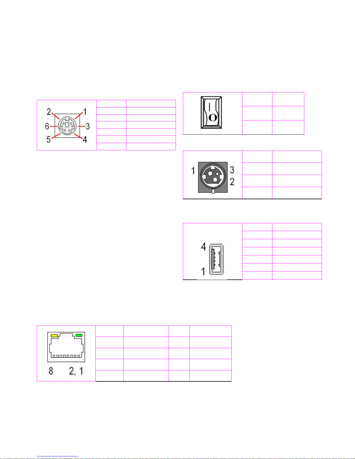
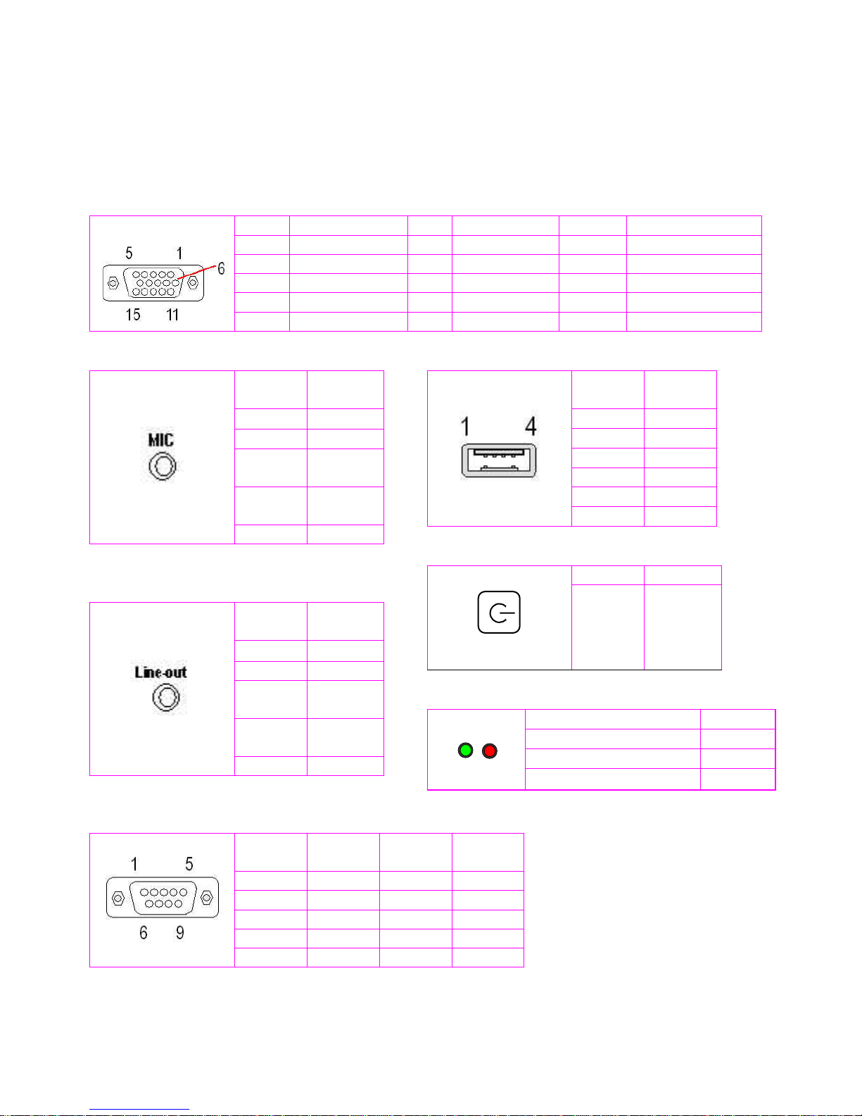
PIN ASSIGNMENTS
J4:PS/2 Keyboard or Mouse – 6-pin Mini-Din
Connector
Pin # Signal Name
1 KBCLK
2 PMCLK
3 GND
4 KBDAT
5 PMDAT
6 SB5V
Power SW – Push Button Switch
Pin # Status
| ON
O OFF
J14: DC-IN (5V) – 3-pin Mini-Din Lock Pin Socket
Pin #
Signal Name
1 VCC
2 GND
3 NC
J3: USB (90
o
)– 4-pin USB Type 1 Connector
(Vert ical Type)
Pin # Signal Name
1 VCC
2 USB03 USB0+
4 GND
5 GGND
6 GGND
J8: RJ-45 Connec tor
Pin # Signal Name Pin # Signal Name
1 FTXD+ 2 FTXD-
3 FRXIN+ 4 NC
5 NC 6 FRXIN-
7 NC 8 NC
Page 25
eBox-2300 17
`
PIN ASSIGNMENTS
J1: VGA – 15-pin D-Sub Connector
Pin # Signal Name Pin # Signal Name Pin # Signal Name
1 MR 6 GND 11 NC
2 MG 7 GND 12 VCC
3 MB 8 GND 13 HYSYNC
4 NC 9 NC 14 VSYNC
5 GND 10 GND 15 VCC
J10: MIC_IN – 5-pin RCA Phone Jack
Pin #
Signal
Name
1 GND
2 MIC1
3
Open
To uc h
4
Open
Touch
5 VREFOUT
J9: Line-out – 5-pin P hone Jack
Pin #
Signal
Name
1 GND
2 LOUTL
3
Open
To uc h
4
Open
Touch
5 VREFOUT
J5:USB (USB2): For connection to external USB
device –4-pin USB Type 1 Connector ( H)
Pin #
Signal
Name
1 VCC
2 USB23 USB2+
4 GND
5 NC
6 NC
Power BTN – Push button
Action Status
Push ON/OFF
LEDS: POWER ON/OFF & HDD R/W
LED Color State
Green Power On
Red HDD On
Red Flashes HDD R/W
J9: COM - 9-pin Dsub Connector
Pin #
Signal
Name
Pin #
Signal
Name
1 DCD1 2 RXD1
3 TXD1 4 DTR1
5 GND 6 DSR1
7 RTS1 8 CTS1
9 RI1 -- --
Page 26

eBox-2300 18
TERMS AND CONDITIONS
1. Warranty
The warranty terms for eBox-2300 are twelve (12) months from the beginning on the
date of invoice. During the warranty period, DMP Electronics Will repair replace the
product covered under this limited warranty.
2. Service and Support
DMP Electronics Inc. provides the technical support for hardware problems with your
system throughout the warranty period. The technical support service is limited to
configuration and operation of eBox-2300 sold by DMP Electronics Inc. The technical
support service does not offer software tutoring or training.
3. Return Merchandise Authorization(RMA)policy
If the DMP staff or dealer determines that a part is defective. Purchaser must call our
technical support service to obtain an RMA number before attempting to return any part.
Please refer to your nearest dealer for
To obtain an RMA number, Purchaser must follow procedures as below:
1. Complete the DMP Electronics Inc. standard RMA Form and fax back to the RMA
Department.
2. The RMA Number must be used within 7 DAYS
3. The RMA Number must be shown clearly on your shipping label.
4. DMP Electronics Inc. must receive all Returns before a replacement will be sent.
5. The repair cost is depends on the parts, the damage reasons, and whether under
warranty period…etc. The Seller will charge the Purchaser in a reasonable price.
6. A copy of the invoice for the RMA product(s) will also be shipped to Purchaser.
7. The freight of return to Media Stream Tech. is charges to Purchaser account and
accompanied by an RMA number. Any Returns with freight collect will be refused and
returned to you. After Repairing, the cost of freight will be paid by Seller.
8. DMP Electronics Inc. must receive all returned goods within the warranty period.
4. Shipping Policy
The Purchaser must pre-pay shipping for any defective system or parts returned under
the warranty. DMP Electronics Inc. shall not be liable for risk of loss or damage during
shipment of your returned system or parts if you fail to insure the shipment.
All products must be shipped back to DMP Electronics Inc. in original or equivalent
packaging. DMP Electronics Inc. will ship the repaired or replacement product(s) to
Purchaser by freight prepaid. Purchaser assumes the risk of loss. DMP Electronics Inc.
shall not be responsible for failure of the delivery service to make on-time delivery.
W
ARRANTY
Page 27

eBox-2300 19
MEMO
 Loading...