

Page 1
En glish
Installation Instruction
UNPACKING INSTRUCTIONS
! Carefully open the carton, remov e co ntent s an d la y ou t on cardboa rd o r ot her
protective s urface to avoid damage.
! Check pa ckage content s aga inst the Supp lied Parts Li st in the nex t page to ass ure
that all c omponents were recei ved u ndama ged. Do not use dama ged or defective
parts.
! Carefully re ad all in structions befo re attempting ins talla tion.
IMPORTANT SAFETY INFORMATION
! Inst all a nd operate th is devic e with ca re. P lease read th is instructio n before
installati on, and carefully follow all instruc tions contained herein . Use proper safety
equipment du ring in stallation.
! Please call a q ualified installation contra ctor for h elp i f you don' t und ersta nd th ese
directions o r have an y doubts about the sa fety of the install ation .
Do not use this produc t for any p urpos e or in any configuration not expli citly specified
in this in struction. We hereby discla ims any and all liabi lity for inju ry or da mage
arising from i ncorr ect assembly, incorre ct moun ting, or incorrec t use of this product.
1
Page 2
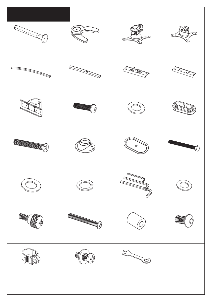
Su pp li ed Par ts List
(1) 48mm Pole- a (1) Weighted Base-b
(2) Long Arm-d1
(2) Arm Clamp-f (8)M6x25 Bol t-g (8)M6 Wash er-h
(2) Short Arm-d 2
(4) Side Vesa Pla te
with Slip Set- c1
(1) Arm Connect
Part-e1
(1) -lGrommet Plat e(1) kDecorative C over-(3)M6x29 Bol t-j
(1) Middle Vesa
Plate-c2
(1) Arm Connect
Part-e2
(4)Arm Plast ic
Cover-i
(1)M10 Gro mme t
Bolt-m
(1)M10 Was her-n1 (1)Spring Washer-n2
(20)M4x12
Thumb Bolt-q
(4)Wire Clip -u (2)M4x16 Bol t with wa sher-v (1)Wrench-w
(20)M4x30 Bo lt-r (4)M8x10 Bol t-t
(1)Allen Key -o
(20)M4 Space -s
2
(40)M4 Was her-p
Page 3

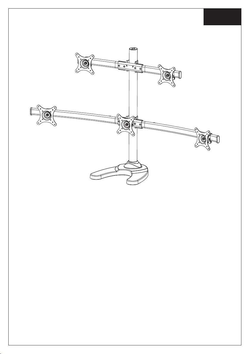
St ep 1
Mounting the base according to your requirement
The sta nd can be used with the we ighte d
metal base or th ere is a desk attachm ent
provided (as d rawings on the b ottom)
allowing you to mount the sta nd on a desk.
This is very simple t o i nstal l a nd just
requires a hole dr illing (10mm d iameter) in
your de sk and clamp ing with the bolt a nd
large washer.
b
Op ti on 2 Op ti on 3
a
Op ti on 1
a
k
j
a
n1
n2
m
k
k
j
b
l
l
n2
n1
m
3
Page 4

St ep 2
Assemble the Arm Sets and Install it on the Pole
d2
h
g
d1
h
g
Assemble the curved arm sets as th e
di ag ram ab ov e, f as ten th e M6x25
Bolt-g by prov ided All en Key-o.
St ep 3
Mount the Monitor to VESA Plate
f
e2
f
e1
u
Insert the c urved a rm sets to p ole,
fasten the M8x10 Bo lt-t by prov ided
Allen Key-o. I nstall the Wire Clip-u.
t
q
p
For Flat Back Monitor
r
p
s
p
For Curved Back Monitor
4
Page 5

St ep 4
Attach the Monitors to Arm Sets
c1
Plastic Knob
c1
c1
v
c1
i
Attaching th e monitors to the cur ved arm sets , fasten the M4x16 Bo lt with
Was her-v, fix ing the po sition by the plast ic knob. I nstal l the Arm Plastic Cov er-i
as the above dia gram.
c2
St ep 5
Adjust the Tilting Angle and the Monitors Level
grub screw
Fasten the grub scr ew to fix the til ting
angle by provi ded Allen Key-o.
Bolt
By fasten o r loosen the bolt o n the
above diag ram to adjust the level of
each monitor.
5
Page 6

St ep 6
Manage the Wires
Thank you for choosing our products!
6
 Loading...