

DMP Electronics 9000 Series, 9060, 9063 Installation Manual
InstallatIon GuIde
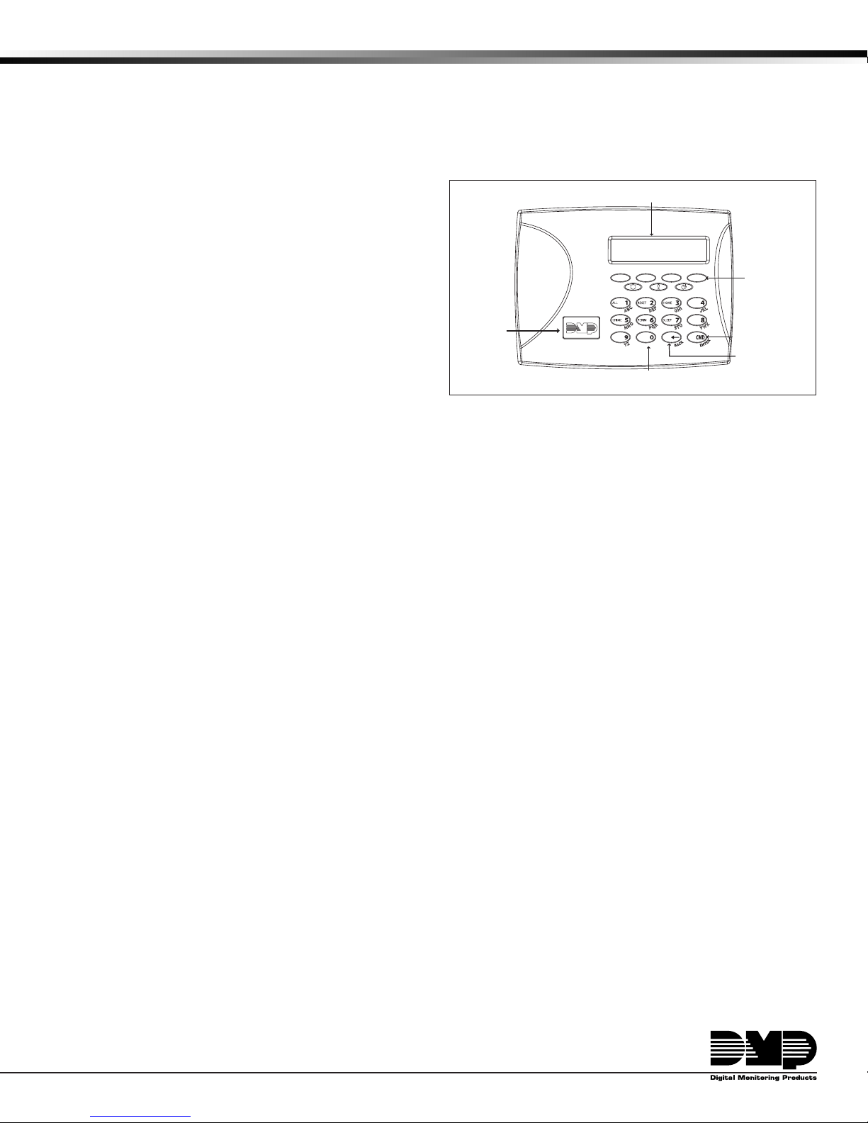
32-Character Display
Data Entry Digit keys
COMMAND Key
Back Arrow Key
Select Keys
Backlit Logo
and Proximity
Antenna
9000 Series Wireless Keypads
Description
The DMP 9060 and 9063 are fully functioning supervised wireless keypads. They provide installation exibility while also
offering optional codeless arming and disarming capabilities. Each keypad provides:
• Custom 16-character home or business name
• Four 2-button Panic keys
• 32-character display
• Backlit keyboard with easy-to-read lettering
• Internal speaker.
• Wall tamper protection
• Keyboard and logo backlighting turns Red in alarm
conditions
The Model 9063 keypad also provides a built-in proximity card
reader designed to read DMP/HID proximity credentials for
codeless arming and disarming.
Compatibility
XTL Panels
What is Included
The 9000 Series Keypad includes the following items:
• One wireless keypad mounted in a Thinline two-part housing (base and cover)
• One 3.7V lithium battery
• One 12 VDC DC Plug-in Power Supply
• Serial number label
Figure 1: 9000 Series Keypad
Keypad Serial Number
For your convenience, an additional pre-printed serial number label is included. Prior to installing the device, record the
serial number or place the pre-printed serial number label on the panel programming sheet. This number is required during
programming. As needed, use the zone name and number label to identify a specic transmitter.
Programming the Transmitter in the Panel
The 9000 Series Wireless Keypads can be programmed into the XTL through panel programming or using the wireless
keypad association mode.
Note: When a receiver is installed, powered up, or the panel is reset, the supervision time for transmitters is reset. If the
receiver has been powered down for more than one hour, wireless transmitters may take up to an additional hour to send
a supervision message unless tripped, tampered, or powered up. This operation extends battery life for transmitters. A
missing message may display on the keypad until the transmitter sends a supervision message.
Device Setup Programming
Refer to the XTL Programming Guide (LT-1107) as needed. Program the keypad as a device in Device Setup during panel
programming. At the Serial Number: prompt, enter the eight-digit serial number. Continue to program the device as
directed in the panel programming guide.
Wireless Keypad Association
Pressing the XTL RESET button 3 times within 5 seconds enables the keypad association mode. For one minute the panel
listens for wireless keypads. Any keypads not already associated with another panel are assigned to the rst open keypad
address. Keypads are automatically assigned addresses based upon the order in which they are detected. A maximum of 4
keypads may be associated with a panel.
Selecting the Proper Location (LED Survey Operation)
The 9000 Series keypad provides a built-in survey capability in the Installer menu to allow one person to conrm keypad
communication with the panel. Refer to Accessing Keypad Wireless Survey later in this document.
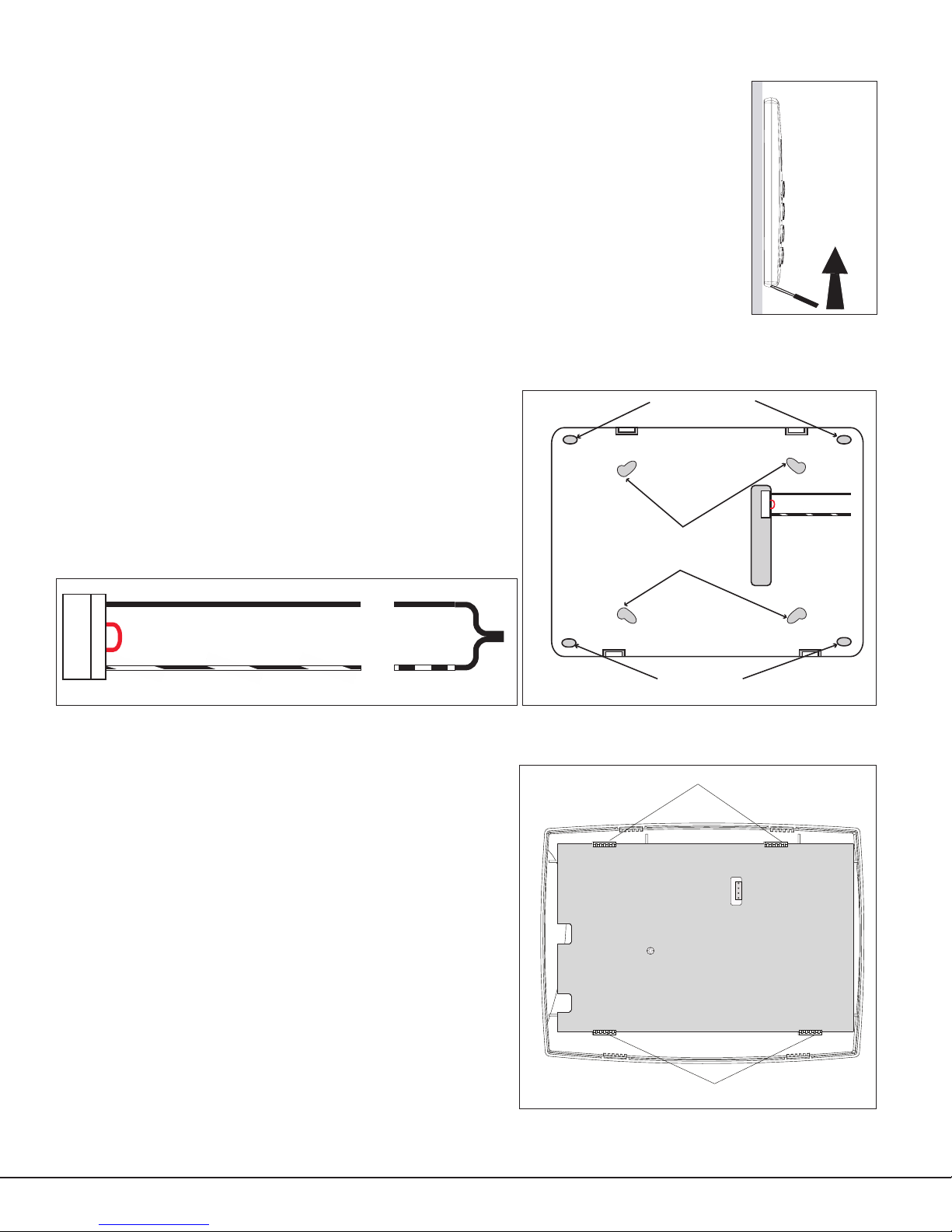
Installing the Keypad
Lift screwdriver
handle up
toward you to
separate keypad
cover from base.
Thinline
or Aqualite
Keypad
Building Wall
Surface and Backbox
Mounting Holes
Combined 4-square
and 3-gang switch box
Mounting Holes
Keypad Back
Surface and Backbox
Mounting Holes
Black (-)
Black/White
stripe (+)
Top PCB Snaps
Bottom PCB Snaps
PCB Alignment post
4 Position
header
Black (-)
371-500
Plug-in
Power
Supply
Keypad
4-Wire
Harness
Black/White
stripe (+)
Black (-)
Black/White
stripe (+)
All DMP keypad housings are designed to easily install on any desk stand, 4” square box, 3-gang switch
box, or a at surface.
Remove the Cover
The keypad housing is made up of two parts: the front, which contains the circuit board and keyboard
components and the base. Use the following steps and gures to separate the keypad front and base.
1. Insert a at screwdriver into one of the slots on the bottom of the keypad and gently lift the
screwdriver handle toward you while pulling the halves apart. Repeat with the other slot.
2. Using your hands, gently separate the front from the base and set the front and components
aside.
DC Power Supply
Locate the keypad near a wall outlet for the Model 371-500 plug-in DC power supply. In addition to
powering the keypad, the power supply also charges the back-up battery. The plug-in power supply
should be located within 100 feet of the keypad using 22 AWG wire or 250 feet using 18 AWG wire. Use
the following steps to connect the plug-in power supply:
1. Connect the plug-in power supply Black wire with White stripe (positive) to the White wire of the included 4-wire
harness.
2. Connect the plug-in power supply solid Black wire (negative)
to the Black wire of the wire harness.
3. Plug the 2-wire harness on to the header on the back of the
keypad.
4. Plug the power supply into a 110 Volt AC outlet not controlled
by a switch.
Figure 2: DC Power Supply Connection
Standby Battery
The keypad rechargeable battery is used to provide 24 hours
of backup battery power when DC power is not available. The
battery is intended for backup power only and not to operate the
keypad on a daily basis. If the battery is low, or not plugged into
the J1 battery connector, a low battery condition is indicated by
the XTL panel. Use the following steps to replace the standby
battery. DMP recommends replacing the battery every 3 years
under normal use.
Note: If removing the keypad from service, disconnect the 4-wire
harness from the back of the keypad.
Removing the Keypad PCB
1. Disconnect the 2-wire harness from the back of the keypad.
2. Remove the base.
3. Loosen the top keypad PCB snaps.
4. Lean the keypad PCB backwards and lift out from the bottom
PCB snaps.
Digital Monitoring Products 9000 Series Installation Guide
2
Figure 3: Mounting Holes
Figure 4: PCB Snaps
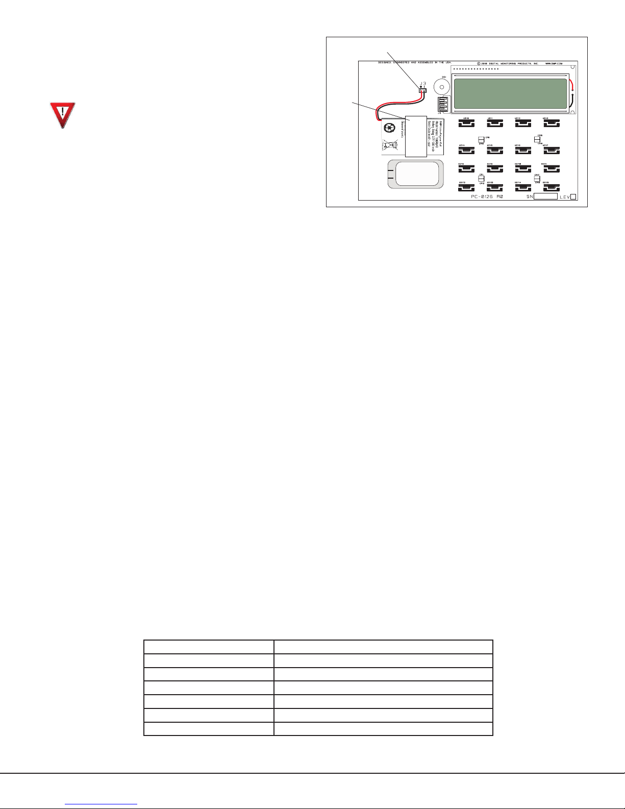
Battery Replacement
Standby battery
connector
Standby
battery
strap
1. Disconnect the battery lead connector from the
keypad J3 battery header.
2. Remove the battery strap from the standby battery.
3. Remove and properly dispose of the used battery.
Caution: Risk of re, explosion, and burns. Do not
disassemble, heat above 212°F (100°C), or incinerate.
Properly dispose of used batteries.
4. Place the new battery on the keypad PCB and replace
the battery strap.
5. Observe polarity and connect the battery lead
connector to the keypad J3 battery header.
Installing Keypad PCB
1. Set the keypad PCB into the bottom snaps
2. Line up the PCB alignment post with the hole in the
Figure 5: Battery Replacement
keypad PCB.
3. Press the PCB into the top PCB snaps to secure in place.
4. Replace the base.
Battery Supervision
The panel tests the battery once every hour when DC power is present. This test occurs 15 minutes past each hour and
lasts for ve seconds. A load is placed on the battery and if the battery voltage is low, a low battery is detected. If DC
power has failed, a low battery is detected any time the battery voltage falls below 3.7V.
Card Reader
When a proximity credential is presented to the Model 9063 internal reader, a beep tone is heard and the Power and Armed
LEDs blink. This provides both an audible and visual acknowledgement of the credential read.
Panic Key Options
2-Button Panic Keys
All keypads offer Panic key function that allows users to send Panic, Emergency, or Fire reports to the central station.
Enable the Panic key function in the keypad user menu. See Keypad Programming Instructions later in this document.
Install the supplied icon labels below the top row of Select keys as shown in Figure 4.
The user must press and hold the two Select keys for two seconds until a beep from the keypad is heard. At the beep, the
panel sends the following zone alarm reports to the central station:
Panic (left two Select keys)—Zone 19 + Device Address
Emergency—non-medical (center two Select keys)—Zone 29 + Device Address
Fire (right two Select keys)—Zone 39 + Device Address
Internal Speaker Operation
All keypads emit standard tones for key presses, entry delay, and system alerts. The speaker also provides distinct
burglary, re, zone monitor, and prewarn cadences. The keypads provide an alternate prewarn with alarm cadence that
occurs when the status list displays a zone alarm.
Backlighting
Both the logo and keyboard light when a key is pressed or the speaker sounds.
During an alarm condition, all lighted areas turn Red. When all alarm conditions are cleared from the display, the Red
display turns off and the lighted areas return to the user-selected brightness.
Backlit Keyboard and Logo
The backlit keyboard and logo indicate the power and armed status of the panel. Depending on the status, the LED
displays in Red or Green as listed in the table.
Color and Activity Operation
Green Steady Panel Disarmed, AC Power OK, Battery OK
Green Blinking Panel Disarmed, AC Power OK, Battery Fault
No Light Panel Disarmed, AC Power Fault, Battery OK
Red Steady Panel Armed, AC Power OK, Battery OK
Red/Green Alternate Panel Armed, AC Power OK, Battery Fault
Red Blinking Panel Armed, AC Power Fault, Battery OK
9000 Series Installation Guide Digital Monitoring Products
3
 Loading...