

Page 1
736P
INSTALLATION GUIDE
736P Radionics™ POPIT Interface Module
Description
The Model 736P Radionics™ POPIT Interface Module allows a Radionics™ POPIT System to interface to a DMP panel,
while maintaining the existing Radionics™ wiring.
The 736P is supervised and connects to either the DMP Keypad bus or LX-Bus™ and supports up to 32 Keypad bus
zones and up to 100 LX-Bus zones.
• For XR100 Series, connect directly to the on‑board LX‑Bus.
• For XR500 Series, connect directly to the on‑board LX‑Bus or to an interface card.
• For an XR150/XR350/XR550 Series, connect directly to the LX500 ‑ LX900 connectors on the panel.
All re device installations must be in accordance with the manufacturer's instructions, NFPA standards, and the
Authority Having Jurisdiction (AHJ) requirements.
Wiring Distance
The maximum wire distance between any 736P and the DMP Keypad bus or LX-Bus circuit is 10 feet. To increase the
wiring distance, install an auxiliary power supply, such as a DMP Model 505‑12. For listed installations, the power
supply must be listed for re protective signaling systems, regulated, and power limited. Refer to the 710 Bus
Splitter/Repeater Module Installation Guide (LT‑0310) for complete information.
Radionics™ Terminology
The Radionics™ ZONEX (Zone Expansion system) is the zone expansion bus, much like the DMP LX-Bus. A POPEX
(Point Of Protection Expander) is the device that provides the ZONEX, similar to a DMP 481 Zone Expansion Interface
Card that provides an LX-Bus.
The POPIT (Point Of Protection Input Transponder) is a device on the ZONEX that provides a point to connect a
protection device to, much like a DMP 711 Single Point Zone Expander Module. Finally, the OctoPOPIT is a ZONEX
device that provides several points to connect protection devices to, similar to a DMP 714‑8 Zone Expander and a
481 combined. A POPEX is not required when using an OctoPOPIT.
Compatible Radionics™ Devices
The 736P Module supports the following Radionics™ POPEX and OctoPOPIT devices:
• D8125 POPEX Zone Expander
• D8128A OctoPOPIT for 63‑point bus
• D8128C OctoPOPIT for 63‑point or 119‑point bus
Mounting to Walls
The 736P ships installed in a decorative high impact plastic case that mounts directly to walls, backboards or
other at surfaces. Wire entrances on the case back and front make installation easy. The plastic case bottom half
contains two screw holes for mounting the case on single-gang switch boxes or rings.
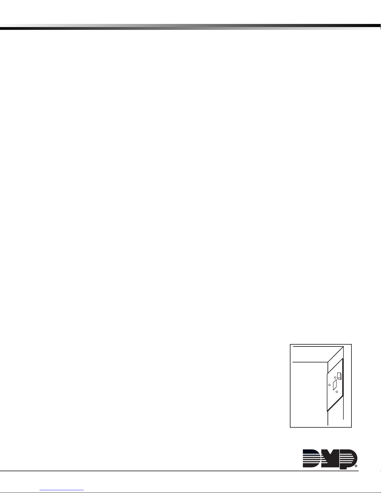
Mounting in Panel Enclosures
The 736P Module can also be installed in DMP enclosures using the standard 3-hole
pattern.
1. Mount the plastic standoffs to the enclosure using the three included Phillips head
screws.
2. Insert the screws from the outside of the enclosure through the holes and into the
plastic standoff which mounts on the inside of the enclosure and tighten.
3. After the securing the standoffs onto the enclosure, snap the 736P onto the
standoffs.
Figure 1: 736P Mounting
Page 2
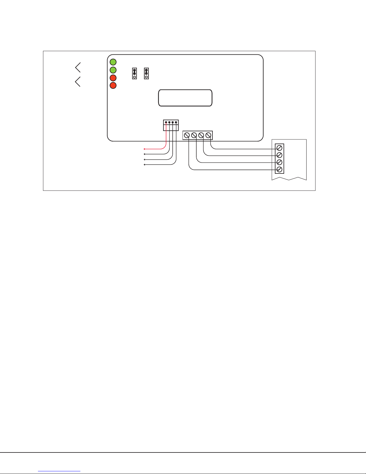
Wiring the 736P
The 736P interfaces with a DMP panel using the keypad bus, LX‑Bus or LX500‑XL900 connectors. After setting the
jumper headers, wire the 736P to the panel and to the Radionics™ modules as described in the following sections
and as illustrated in Figure 2.
DMP Bus
Radionics™
Bus
Receive Data
Transmit Data
Receive Data
Transmit Data
All circuits are supervised Class B style 3.5.
All circuits are power limited Class 2.
DRXD
DTXD
ZRXD
ZTXD
Connect to
Keypad Bus
or LX-Bus
736P DMP Bus Header (J1)
When connecting to the Keypad bus, place the J1 jumper across the two bottom pins marked KEY. When connecting
to the LX-Bus, place the J1 jumper across the two top pins marked LX.
736P DMP Bus Connector (J2)
For Keypad bus connection, connect the provided dual‑ended 4‑wire harness from the DMP BUS header (J2) to the
panel J8 header.
736P to XR100/XR500
For LX‑Bus connection, plug the provided dual‑ended 4‑wire harness from the DMP BUS header (J2) onto the panel
on-board LX-Bus (J22) or an installed interface card.
736P to XR150/XR350/XR550
For LX‑Bus connection, plug the provided dual‑ended 4‑wire harness from the DMP BUS header (J2) onto the panel
on‑board LX500 ‑ LX900 connectors on the panel.
Wiring Specications for Keypad or LX-Bus
1. DMP recommends using 18 or 22‑gauge unshielded wire for all keypad and LX-Bus circuits. Do Not use twisted
pair or shielded wire for LX-Bus and keypad bus data circuits. To maintain auxiliary power integrity when
using 22‑gauge wire do not exceed 500 feet. When using 18‑gauge wire do not exceed 1,000 feet. Install an
additional power supply to increase the wire length or add devices.
2. Maximum distance for any one circuit (length of wire) is 2,500 feet regardless of the wire gauge. This distance
can be in the form of one long wire run or multiple branches with all wiring totaling no more than 2,500 feet.
As wire distance from the panel increases, DC voltage on the wire decreases.
3. Maximum number of devices per 2,500 foot circuit is 40.
Note: Each panel allows a specic number of supervised keypads. Add additional keypads in the unsupervised
mode. Refer to the panel installation guide for the specic number of supervised keypads allowed.
4. Maximum voltage drop between the panel (or auxiliary power supply) and any device is 2.0 VDC. If the voltage
at any device is less than the required level, add an auxiliary power supply at the end of the circuit. When
voltage is too low, the devices cannot operate properly.
For additional information refer to the panel installation guide and LX‑Bus/Keypad Bus Wiring Application Note
(LT‑2031) or the 710/710F Installation Guide (LT‑0310).
Zone Expander Connector (J3)
Connect the Radionics™ POPEX and OctoPOPIT modules to the (J3) connector on 736P ZONE EXPANDER. The
maximum wire distance between the 736P and any Radionics™ POPEX and OctoPOPIT is 10 feet.
ZONEX Bus Header (J4)
This jumper selects the type of Radionics™ ZONEX Bus that connects to the 736P module. To select a 63‑point
(horizontal or vertical) bus, place the J4 jumper across the two top pins marked 63. To select the expanded,
119‑point bus, place the J4 jumper across the two bottom pins marked 119. See Figure 2.
Digital Monitoring Products 736P Installation Guide
2
LX
63
J4
J1
KEY
119
DMP Bus
RED
J2
Red
Yellow
Green
Black
Figure 2: 736P Wiring
736P Radionics™ POPIT
Interface Module
BLK
Zone Expander
J3
ZX
+AUX
DOUT
COM to COM
COM
DOUT to IN
ZX to OUT
+ AUX to AUX
Radionics™
POPEX or
OctoPOPIT
COM
IN
OUT
AUX
Page 3

POPEX Power Wiring
Because the Radionics D8125 Zone Expander is rated to operate over a voltage range of 10.2 to 14 VDC, 50mA, a power
supply must be listed for re protective signaling systems, power limited, and provide a voltage range within 10.2 VDC
to 14.0 VDC.
Aux Power
Power
Common
DMP panel
736P
Existing Radionics™ POPIT Modules
Data In
Common
Power
Data Out
Existing
POPEX
Existing 2-Wire
Figure 3: 736P With Radionics™ POPIT System
Converting ZONEX Points to DMP Zones
At power up the 736P communicates with the Radionics™ POPEX or OctoPOPIT module and creates a table of
equivalent DMP zone addresses. The current zone states are received from the Radionics™ module and transmitted
to the DMP panel (Normal, Open, Shorted). The conversion tables show the Radionics™ point number and the
corresponding DMP zone number for the LX-Bus™ and Keypad Bus. Once the corresponding DMP zone is determined
from the tables, it must be programmed into the panel.
How to Use the Tables
The conversion tables on the following pages provide the Radionics™ ZONEX module switch setting and the expanded
119‑point Radionics™ ZONEX Bus #1 and ZONEX Bus #2 numbers.
To nd a corresponding DMP zone from either table, select the Radionics™ ZONEX point, the appropriate DMP bus
type, and the appropriate DMP panel type. Table 1 lists the Keypad bus numbers for all DMP panels. Table 2 lists
LX‑Bus numbers for XR100/XR500 and XR150/XR350/XR550 Series panels.
Note: XR100 and XR150 Series panels only support LX‑Bus 1 (LX500) zone numbers.
Find the ZONEX Bus point number in Table 1 and the corresponding DMP Keypad bus zone number is listed in one
of the columns to the right. For Table 2, nd the ZONEX Bus point number and the corresponding DMP LX‑Bus zone
number is listed in one of the columns to the right.
Example: ZONEX Bus #1 point 022 on the expanded 119‑point ZONEX Bus connected to a DMP LX‑Bus 1 corresponds
to DMP zone 513 on an XR100/XR500 panel.
Note: Radionics™ points 109 to 127 and 229 to 247 are not supported. Those ZONEX Bus points can be reassigned to
any available unused zones on the DMP panel.
Zone Finder Feature
The Zone Finder feature built into the XR100/XR500 and XR150/XR350/XR550 Series panels is a diagnostic function
that allows an installer to identify an unknown zone in the system. To identify a zone, fault the Radionics point
and the panel identies the zone by displaying the equivalent DMP zone number at the keypad. Refer to the panel
programming guide for additional information on this feature.
Compliance Listing Specications
To comply with ANSI/UL 365 Police‑Connected Burglary Systems or ANSI/UL 609 Local Burglary Alarm Systems, the
736P Module must be mounted in a Listed enclosure with a tamper installed.
For listed re applications, the wiring connection must be 18 gauge or greater, unless the wire complies with the
requirements of the NEC 1999, and the wiring consists of two or more insulated conductors under a non‑metallic jacket.
736P Installation Guide Digital Monitoring Products
3
Page 4

Table 1: ZONEX Bus to DMP Panel Keypad Bus Zone Conversion
ZONEX Bus #1 ZONEX Bus #2 Keypad Bus
Switch Settings
Expansion
(119)
0 1 2 3 4 5 6 9 129 11 11 11
0 1 2 3 4 5 — 10 130 12 12 12
0 1 2 3 4 — 6 11 131 13 13 13
0 1 2 3 4 — — 12 132 14 14 14
0 1 2 3 — 5 6 13 133 21 21 21
0 1 2 3 — 5 — 14 134 22 22 22
0 1 2 3 — — 6 15 135 23 23 23
0 1 2 3 — — — 16 136 24 24 24
0 1 2 — 4 5 6 17 137 31 31 31
0 1 2 — 4 5 — 18 138 32 32 32
0 1 2 — 4 — 6 19 139 33 33 33
0 1 2 — 4 — — 20 140 34 34 34
0 1 2 — — 5 6 21 141 41 41 41
0 1 2 — — 5 — 22 142 42 42 42
0 1 2 — — — 6 23 143 43 43 43
0 1 2 — — — — 24 144 44 44 44
0 1 — 3 4 5 6 25 145 51 51 51
0 1 — 3 4 5 — 26 146 52 52 52
0 1 — 3 4 — 6 27 147 53 53 53
0 1 — 3 4 — — 28 148 54 54 54
0 1 — 3 — 5 6 29 149 61 61 61
0 1 — 3 — 5 — 30 150 62 62 62
0 1 — 3 — — 6 31 151 63 63 63
0 1 — 3 — — — 32 152 64 64 64
0 1 — — 4 5 6 33 153 71 71 71
0 1 — — 4 5 — 34 154 72 72 72
0 1 — — 4 — 6 35 155 73 73 73
0 1 — — 4 — — 36 156 74 74 74
0 1 — — — 5 6 37 157 81 81 81
0 1 — — — 5 — 38 158 82 82 82
0 1 — — — — 6 39 159 83 83 83
0 1 — — — — — 40 160 84 84 84
0 — 2 3 4 5 6 41 161 91
0 — 2 3 4 5 — 42 162 92
0 — 2 3 4 — 6 43 163 93
0 — 2 3 4 — — 44 164 94
0 — 2 3 — 5 6 45 165 101
0 — 2 3 — 5 — 46 166 102
0 — 2 3 — — 6 47 167 103
0 — 2 3 — — — 48 168 104
0 — 2 — 4 5 6 49 169 111
0 — 2 — 4 5 — 50 170 112
0 — 2 — 4 — 6 51 171 113
0 — 2 — 4 — — 52 172 114
0 — 2 — — 5 6 53 173 121
0 — 2 — — 5 — 54 174 122
0 — 2 — — — 6 55 175 123
0 — 2 — — — — 56 176 124
0 — — 3 4 5 6 57 177 131
0 — — 3 4 5 — 58 178 132
0 — — 3 4 — 6 59 179 133
0 — — 3 4 — — 60 180 134
0 — — 3 — 5 6 61 181 141
0 — — 3 — 5 — 62 182 142
0 — — 3 — — 6 63 183 143
0 — — 3 — — — 64 184 144
0 — — — 4 5 6 65 185 151
0 — — — 4 5 — 66 186 152
0 — — — 4 — 6 67 187 153
0 — — — 4 — — 68 188 154
0 — — — — 5 6 69 189 161
0 — — — — 5 — 70 190 162
0 — — — — — 6 71 191 163
0 — — — — — — 72 192 164
Digital Monitoring Products 736P Installation Guide
4
Expansion
(119)
XT30/XT50
XR100
XR150
XR500 Series
XR350/XR550 Series
Page 5

Table 2: ZONEX Bus to DMP LX-Bus Zone Conversion
Switch Settings
ZONEX
Bus #1
Expansion (119)
XR100/XR500 Series (LX-Bus #1 ONLY)
XR150/XR350/XR550 Series
#1
(LX500)
#2
(LX600)
#3
(LX700)
#4
(LX800)
(LX900)
#5
ZONEX
Bus #2
Expansion (119)
XR100/XR500 Series (LX-Bus #1 ONLY)
XR150/XR350/XR550 Series
#1
(LX500)
#2
(LX600)
#3
(LX700)
#4
(LX800)
(LX900)
#5
0 1 2 3 4 5 6 9 500 600 700 800 900 129 500 600 700 800 900
0 1 2 3 4 5 — 10 501 601 701 801 901 130 501 601 701 801 901
0 1 2 3 4 — 6 11 502 602 702 802 902 131 502 602 702 802 902
0 1 2 3 4 — — 12 503 603 703 803 903 132 503 603 703 803 903
0 1 2 3 — 5 6 13 504 604 704 804 904 133 504 604 704 804 904
0 1 2 3 — 5 — 14 505 605 705 805 905 134 505 605 705 805 905
0 1 2 3 — — 6 15 506 606 706 806 906 135 506 606 706 806 906
0 1 2 3 — — — 16 507 607 707 807 907 136 507 607 707 807 907
0 1 2 — 4 5 6 17 508 608 708 808 908 137 508 608 708 808 908
0 1 2 — 4 5 — 18 509 609 709 809 909 138 509 609 709 809 909
0 1 2 — 4 — 6 19 510 610 710 810 910 139 510 610 710 810 910
0 1 2 — 4 — — 20 511 611 711 811 911 140 511 611 711 811 911
0 1 2 — — 5 6 21 512 612 712 812 912 141 512 612 712 812 912
0 1 2 — — 5 — 22 513 613 713 813 913 142 513 613 713 813 913
0 1 2 — — — 6 23 514 614 714 814 914 143 514 614 714 814 914
0 1 2 — — — — 24 515 615 715 815 915 144 515 615 715 815 915
0 1 — 3 4 5 6 25 516 616 716 816 916 145 516 616 716 816 916
0 1 — 3 4 5 — 26 517 617 717 817 917 146 517 617 717 817 917
0 1 — 3 4 — 6 27 518 618 718 818 918 147 518 618 718 818 918
0 1 — 3 4 — — 28 519 619 719 819 919 148 519 619 719 819 919
0 1 — 3 — 5 6 29 520 620 720 820 920 149 520 620 720 820 920
0 1 — 3 — 5 — 30 521 621 721 821 921 150 521 621 721 821 921
0 1 — 3 — — 6 31 522 622 722 822 922 151 522 622 722 822 922
0 1 — 3 — — — 32 523 623 723 823 923 152 523 623 723 823 923
0 1 — — 4 5 6 33 524 624 724 824 924 153 524 624 724 824 924
0 1 — — 4 5 — 34 525 625 725 825 925 154 525 625 725 825 925
0 1 — — 4 — 6 35 526 626 726 826 926 155 526 626 726 826 926
0 1 — — 4 — — 36 527 627 727 827 927 156 527 627 727 827 927
0 1 — — — 5 6 37 528 628 728 828 928 157 528 628 728 828 928
0 1 — — — 5 — 38 529 629 729 829 929 158 529 629 729 829 929
0 1 — — — — 6 39 530 630 730 830 930 159 530 630 730 830 930
0 1 — — — — — 40 531 631 731 831 931 160 531 631 731 831 931
0 — 2 3 4 5 6 41 532 632 732 832 932 161 532 632 732 832 932
0 — 2 3 4 5 — 42 533 633 733 833 933 162 533 633 733 833 933
0 — 2 3 4 — 6 43 534 634 734 834 934 163 534 634 734 834 934
0 — 2 3 4 — — 44 535 635 735 835 935 164 535 635 735 835 935
0 — 2 3 — 5 6 45 536 636 736 836 936 165 536 636 736 836 936
0 — 2 3 — 5 — 46 537 637 737 837 937 166 537 637 737 837 937
0 — 2 3 — — 6 47 538 638 738 838 938 167 538 638 738 838 938
0 — 2 3 — — — 48 539 639 739 839 939 168 539 639 739 839 939
0 — 2 — 4 5 6 49 540 640 740 840 940 169 540 640 740 840 940
0 — 2 — 4 5 — 50 541 641 741 841 941 170 541 641 741 841 941
0 — 2 — 4 — 6 51 542 642 742 842 942 171 542 642 742 842 942
0 — 2 — 4 — — 52 543 643 743 843 943 172 543 643 743 843 943
0 — 2 — — 5 6 53 544 644 744 844 944 173 544 644 744 844 944
0 — 2 — — 5 — 54 545 645 745 845 945 174 545 645 745 845 945
0 — 2 — — — 6 55 546 646 746 846 946 175 546 646 746 846 946
0 — 2 — — — — 56 547 647 747 847 947 176 547 647 747 847 947
0 — — 3 4 5 6 57 548 648 748 848 948 177 548 648 748 848 948
0 — — 3 4 5 — 58 549 649 749 849 949 178 549 649 749 849 949
0 — — 3 4 — 6 59 550 650 750 850 950 179 550 650 750 850 950
0 — — 3 4 — — 60 551 651 751 851 951 180 551 651 751 851 951
0 — — 3 — 5 6 61 552 652 752 852 952 181 552 652 752 852 952
0 — — 3 — 5 — 62 553 653 753 853 953 182 553 653 753 853 953
0 — — 3 — — 6 63 554 654 754 854 954 183 554 654 754 854 954
0 — — 3 — — — 64 555 655 755 855 955 184 555 655 755 855 955
0 — — — 4 5 6 65 556 656 756 856 956 185 556 656 756 856 956
0 — — — 4 5 — 66 557 657 757 857 957 186 557 657 757 857 957
0 — — — 4 — 6 67 558 658 758 858 958 187 558 658 758 858 958
736P Installation Guide Digital Monitoring Products
5
Page 6

Switch Settings
ZONEX
Bus #1
Expansion (119)
XR100/XR500 Series (LX-Bus #1 ONLY)
XR150/XR350/XR550 Series
#1
(LX500)
#2
(LX600)
#3
(LX700)
#4
(LX800)
(LX900)
#5
ZONEX
Bus #2
Expansion (119)
XR100/XR500 Series (LX-Bus #1 ONLY)
XR150/XR350/XR550 Series
#1
(LX500)
#2
(LX600)
#3
(LX700)
#4
(LX800)
(LX900)
#5
0 — — — 4 — — 68 559 659 759 859 959 188 559 659 759 859 959
0 — — — — 5 6 69 560 660 760 860 960 189 560 660 760 860 960
0 — — — — 5 — 70 561 661 761 861 961 190 561 661 761 861 961
0 — — — — — 6 71 562 662 762 862 962 191 562 662 762 862 962
0 — — — — — — 72 563 663 763 863 963 192 563 663 763 863 963
— 1 2 3 4 5 6 73 564 664 764 864 964 193 564 664 764 864 964
— 1 2 3 4 5 — 74 565 665 765 865 965 194 565 665 765 865 965
— 1 2 3 4 — 6 75 566 666 766 866 966 195 566 666 766 866 966
— 1 2 3 4 — — 76 567 667 767 867 967 196 567 667 767 867 967
— 1 2 3 — 5 6 77 568 668 768 868 968 197 568 668 768 868 968
— 1 2 3 — 5 — 78 569 669 769 869 969 198 569 669 769 869 969
— 1 2 3 — — 6 79 570 670 770 870 970 199 570 670 770 870 970
— 1 2 3 — — — 80 571 671 771 871 971 200 571 671 771 871 971
— 1 2 — 4 5 6 81 572 672 772 872 972 201 572 672 772 872 972
— 1 2 — 4 5 — 82 573 673 773 873 973 202 573 673 773 873 973
— 1 2 — 4 — 6 83 574 674 774 874 974 203 574 674 774 874 974
— 1 2 — 4 — — 84 575 675 775 875 975 204 575 675 775 875 975
— 1 2 — — 5 6 85 576 676 776 876 976 205 576 676 776 876 976
— 1 2 — — 5 — 86 577 677 777 877 977 206 577 677 777 877 977
— 1 2 — — — 6 87 578 678 778 878 978 207 578 678 778 878 978
— 1 2 — — — — 88 579 679 779 879 979 208 579 679 779 879 979
— 1 — 3 4 5 6 89 580 680 780 880 980 209 580 680 780 880 980
— 1 — 3 4 5 — 90 581 681 781 881 981 210 581 681 781 881 981
— 1 — 3 4 — 6 91 582 682 782 882 982 211 582 682 782 882 982
— 1 — 3 — 5 6 93 584 684 784 884 984 213 584 684 784 884 984
— 1 — 3 — 5 — 94 585 685 785 885 985 214 585 685 785 885 985
— 1 — 3 — — 6 95 586 686 786 886 986 215 586 686 786 886 986
— 1 — 3 — — — 96 587 687 787 887 987 216 587 687 787 887 987
— 1 — — 4 5 6 97 588 688 788 888 988 217 588 688 788 888 988
— 1 — — 4 5 — 98 589 689 789 889 989 218 589 689 789 889 989
— 1 — — 4 — 6 99 590 690 790 890 990 219 590 690 790 890 990
— 1 — — 4 — — 100 591 691 791 891 991 220 591 691 791 891 991
— 1 — — — 5 6 101 592 692 792 892 992 221 592 692 792 892 992
— 1 — — — 5 — 102 593 693 793 893 993 222 593 693 793 893 993
— 1 — — — — 6 103 594 694 794 894 994 223 594 694 794 894 994
— 1 — — — — — 104 595 695 795 895 995 224 595 695 795 895 995
— — 2 3 4 5 6 105 596 696 796 896 996 225 596 696 796 896 996
— — 2 3 4 5 — 106 597 697 797 897 997 226 597 697 797 897 997
— — 2 3 4 — 6 107 598 698 798 898 998 227 598 698 798 898 998
— — 2 3 4 — — 108 599 699 799 899 999 228 599 699 799 899 999
Specications
Operating Voltage 12 VDC
Current Draw 25mA
Dimensions
Wire Specication
4.5” W x 2.75” H x 1.75” D
Accepts 12 to 22 AWG wire
Panel Compatibility
XR150/XR350/XR550 Series,
XR100/XR500 Series,
XT Series
Radionics™ Compatibility
D8125 POPEX Zone Expander
D8128A OctoPOPIT for 63‑point bus
D8128C OctoPOPIT for 63‑point or 119‑point bus
800-641-4282
www.dmp.com 2500 North Partnership Boulevard
Designed, Engineered and
Assembled in U.S.A.
Listings and Approvals
California State Fire Marshal (CSFM)
New York City (FDNY COA #6123)
Underwriters Laboratories (UL) Listed
Commercial Burglar and Fire Accessory Radionics
Interface Module
ANSI/UL 365 Police Connected Burglar
ANSI/UL 609 Local Burglar
ANSI/UL 864 Fire Protective Signaling
ANSI/UL 985 Household Fire Warning
ANSI/UL 1023 Household Burglar
ANSI/UL 1076 Proprietary Burglar
ANSI/UL 1610 Central Station Burglar
ANSI/UL 1635 Digital Burglar
INTRUSION • FIRE • ACCESS • NETWORKS
Springeld, Missouri 65803-8877
13385
LT-0427 1.02 © 2013 Digital Monitoring Products, Inc.
 Loading...