

Page 1
INSTALLATION AND PROGRAMMING GUIDE
734N Wiegand
Interface Modules
Page 2

Page 3

About the 734N/734N-POE ...................... 1
Power Supply ......................................................... 1
Zone Terminals ...................................................... 1
Annunciators .......................................................... 1
Indicator LEDs ....................................................... 1
Form C Relay ......................................................... 2
Programming Connection ................................ 2
PCB Features ...............................................3
Install the 734N...........................................4
Mount the Device ................................................4
Wire the Electronic Lock .................................. 5
Network Connection .......................................... 5
Isolation Relay ...................................................... 8
Install the 333 Suppressor ............................... 9
Wire the Zone Terminals ..................................10
Connect a Card Reader ....................................13
Addressing the 734N ........................................ 15
TABLE OF CONTENTS
Program the 734N .................................... 17
Program Start Display ......................................18
Initialization Option ........................................... 18
Initialize Confirm Option .................................18
Communication Menu ....................................... 18
734N DHCP ...........................................................19
734N IP Address .................................................19
Subnet Mask .........................................................19
Gateway Address ...............................................19
Panel IP Address ................................................. 19
Panel IP Port ........................................................20
734N Passphrase ...............................................20
Access Options ..................................................20
Activate Zone 2 Bypass ...................................21
Zone 2 Bypass Time ......................................... 22
Relock on Zone 2 Change .............................. 22
Activate Zone 3 Request to Exit .................23
Zone 3 REX Strike Time .................................. 23
Activate On-board Speaker ..........................24
Page 4

Custom Card Definitions .........................25
Card Options ....................................................... 25
Wiegand Code Length ....................................26
Site Code Position and Length ....................26
User Code Position and Length ...................26
Require Site Code .............................................27
Site Code ..............................................................27
Enter Site Code ..................................................28
Number of User Code Digits ......................... 28
No Communication with Panel ....................29
Remove Keypad ................................................ 30
Public Card Formats ................................ 31
734N Network Specifications .................32
Compliance Listing Specifications ....... 34
UL Access Control .............................................34
ULC Commercial Burglary (XR150/XR550
Series Panels) ......................................................34
Certifications .............................................35
Underwriters Laboratory (UL Listed) ........ 35
International Certifications .....................37
Intertek (ETL) Listed* ......................................37
Export Control .................................................... 37
Product Specifications ............................38
Readers and Credentials ........................40
Page 5

Digital Monitoring Products, Inc. | 734N Installation and Programming Guide 1
ANNUNCIATORS
An on-board programmable piezo provides local
annunciation at the 734N. You can also connect
a variety of switched ground annunciators to the
734N for remote annunciation.
INDICATOR LEDS
The 734N provides three indicator LEDs. The
red LED turns on for the same duration as the
door strike relay. The yellow LED turns on for one
second to indicate receipt of a valid Wiegand
input. The green LED indicates that data is being
sent to the panel.
The 734N and 734N-POE Wiegand Interface Modules allows you to add IP network access control
capability to XR150/XR550 and XR150INT/XR550INT Series panels using proximity credential or
mag-stripe card readers. The modules also allow you to use the powerful built-in access control
capability of DMP Panels.
POWER SUPPLY
The 734N operates at 12/24 VDC from the power
supply supporting a door’s magnetic lock or
door-strike. It can also be powered from POE.
The 734N provides a 10 Amp Form C relay
contact for lock control.
ZONE TERMINALS
Four input zones are provided to allow
connection of nearby burglary devices.
ABOUT THE 734N/734N-POE
Page 6

2 734N Installation and Programming Guide | Digital Monitoring Products, Inc.
FORM C RELAY
The 734N’s Form C relay draws up to 35 mA of current. See NC/C/NO (Dry Contact Relay) and
Isolation Relay for more information.
PROGRAMMING CONNECTION
The 734N also provides a keypad programming connection that allows you to use a standard DMP
LCD keypad for initial setup. Programming can be completed using a keypad connected to the 734N
or from an XR150/XR550 or XR150INT/XR550INT panel.
Page 7
Digital Monitoring Products, Inc. | 734N Installation and Programming Guide 3
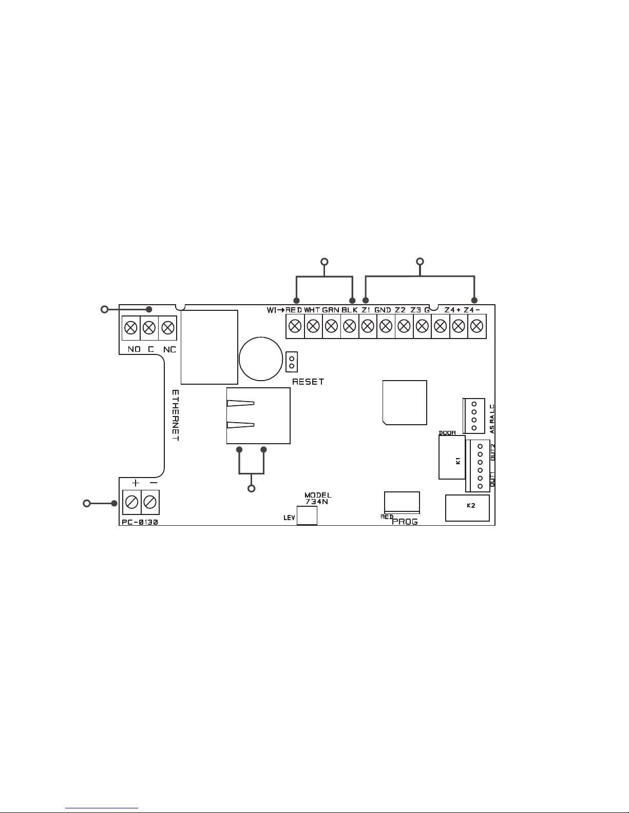
PCB FEATURES
DC INPUT
WIEGAND
INPUTS
ZONES
PIEZO
INDICATOR
LEDS
DOOR RELAY
NETWORK
CONNECTION
Figure 1: PCB Features
Page 8
4 734N Installation and Programming Guide | Digital Monitoring Products, Inc.
INSTALL THE 734N
The 734N comes in a high-impact plastic housing that you can mount directly to a wall,
backboard, or other flat surface.
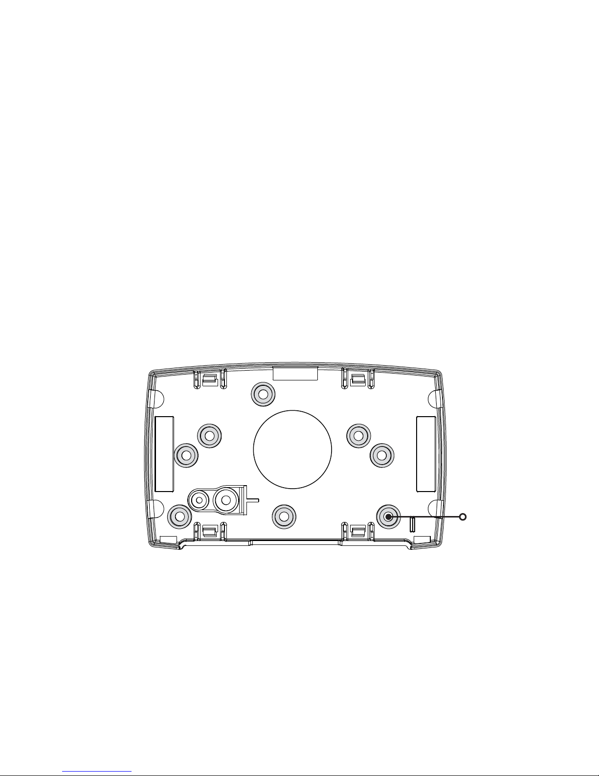
DMP recommends mounting the 734N near the protected door. For easy installation, the back and
ends of the 734N housing have wire entrances. The back also contains multiple mounting holes
that allow you to mount the 734N on a single-gang switch box. See Figure2 for mounting hole
locations on the housing base.
1
MOUNT THE DEVICE
Mounting Hole
Figure 2: Mounting Hole Locations
Page 9

Digital Monitoring Products, Inc. | 734N Installation and Programming Guide 5
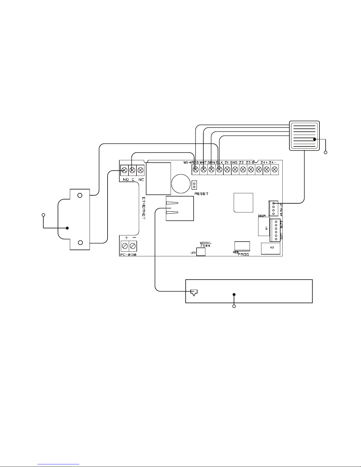
The 734N provides a Form C (SPDT) relay for controlling locks and other electronicallycontrolled barriers. The three relay terminals marked NO C NC allow you to connect the device
wiring to the relay for module control.
When the 734N is powered with a 12/24 V power supply or POE, the device can power an
electric strike, up to 750 mA. See Figures 3 and 4 for typical magnetic lock and door strike
wiring. See Figure 5 for POE door strike wiring.
The Form C relay draws up to 35 mA of current and contacts are rated for 10 Amps (resistive)
at 12/24 VDC. When connecting multiple locks to the Form C relay, the total current for all locks
cannot exceed 10 Amps. If the total current for all locks exceeds 10 Amps, problems may arise
and an isolation relay may be needed. See Isolation Relay for more information.
NETWORK CONNECTION
Connect an IP network cable from the LAN/WAN connection to the 734N Network connector.
The 734N communicates AES encrypted TCP with panels that have network installed.
Two LED’s are located on the ethernet jack.
▸ The green LED indicates data sent to the panel.
▸ The yellow LED indicates the speed of the transmission. A solid yellow LED indicates
the network is connected at 100 Base-T. A flashing yellow LED indicates the network is
connected at 10 Base-T.
2
WIRE THE ELECTRONIC LOCK
Page 10
6 734N Installation and Programming Guide | Digital Monitoring Products, Inc.
PROG
J2
RED RED
KYPD IN
J4
J1
DATA
XMT LED
WIEGAND
READ LED
RELAY
ON
NCCNO
GRNYELRED
Model 333
Supressor
Normally Closed
–
+
Magnetic Door Lock
12/24 VDC
Power Supply
Figure 3: Typical
Magnetic Lock Wiring
PROG
J2
RED
J1
DATA
XMT LED
WIEGAND
READ LED
RELAY
ON
NCCNO
GRNYELRED
Model 333
Supressor
Normally Open
–+
DC Door Strike
12/24 VDC
Power Supply
Figure 4: Typical Door Strike
Wiring with Power Supply
Page 11
Digital Monitoring Products, Inc. | 734N Installation and Programming Guide 7
Door Strike
POE Switch or Injector
Card Reader
Figure 5: Typical Door
Strike Wiring with POE
Page 12
8 734N Installation and Programming Guide | Digital Monitoring Products, Inc.
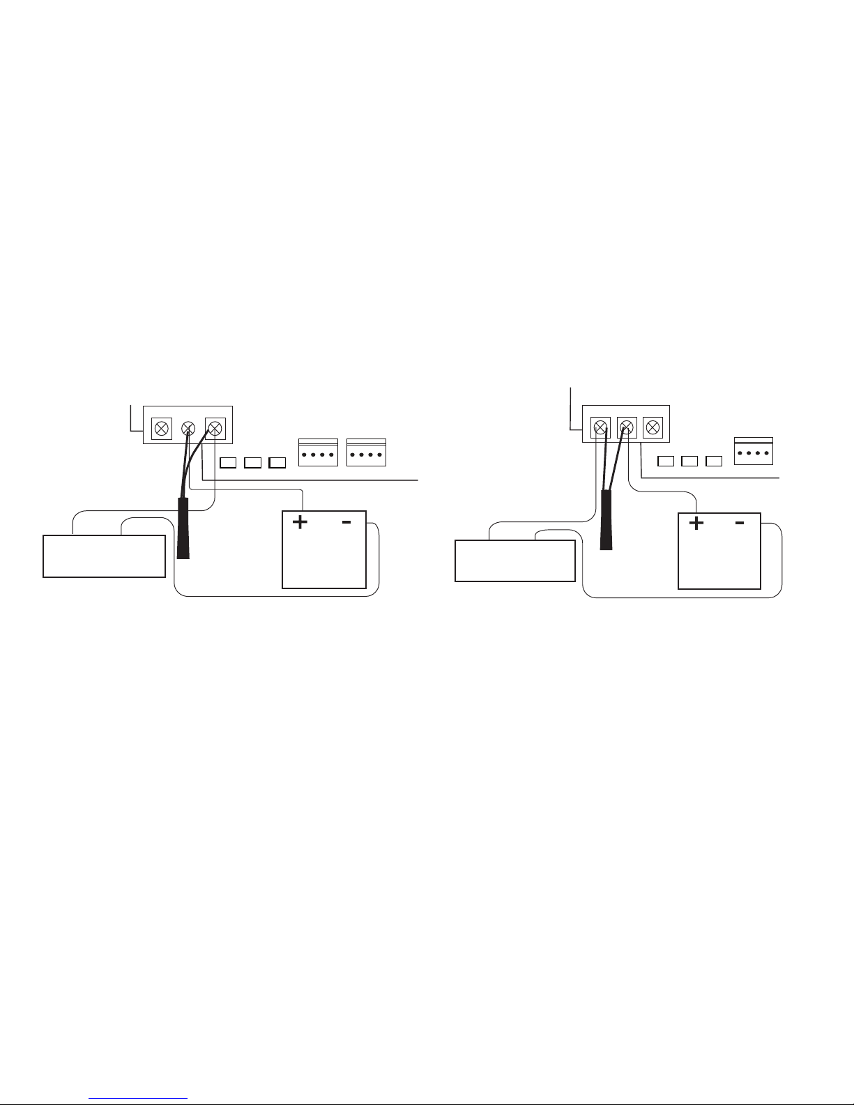
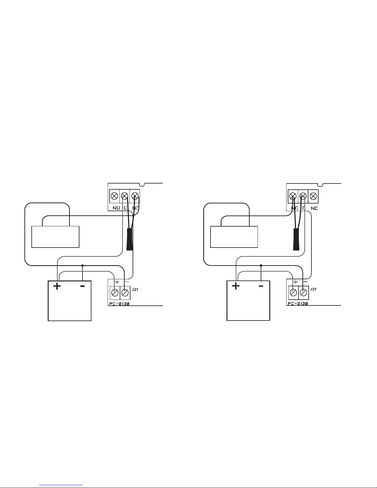
The Form C relay can control a device that draws less than 10 Amps of current. If a device draws
more than 10 Amp of current, or the sum of all devices controlled by the Form C relay exceeds
10 Amps, an isolation relay must be used. Refer to Figures 6 and 7 for isolation relay wiring.
3
ISOLATION RELAY
Figure 6: Magnetic Lock with
an Isolation Relay
Figure 7: Door Strike with
an Isolation Relay
(optional)
Normally
Closed
Magnetic Lock
Model 333
Supressor
–+
12/24VDC
Power
Supply
734N
Interface
Module
DC Input
Model 333
Supressor
Normally
Open
–+
DC Door Strike
12/24VDC
Power
Supply
734N
Interface
Module
DC Input
Page 13
Digital Monitoring Products, Inc. | 734N Installation and Programming Guide 9
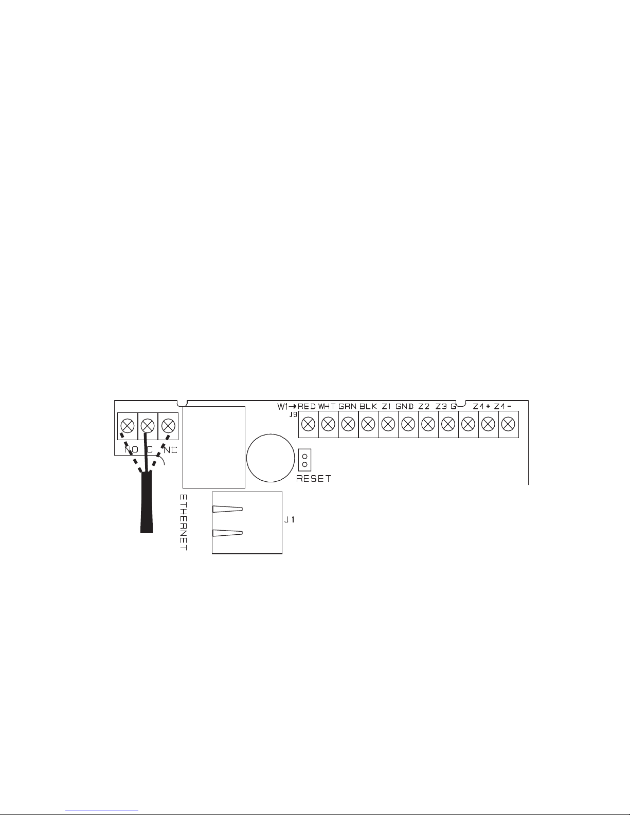
734N
Interface
Module
Model 333
Supressor
Use the included 333 suppressor with the 734N to suppress any surges caused by energizing a
magnetic lock or door strike.
Install the 333 across the 734N C (common) and NO (normally open) or NC (normally closed)
terminals.
If the device being controlled by the relay is connected to the NO and C terminals, install the
suppressor on the NO and C terminals.
Conversely, if the device is connected to the NC and C terminals, install the 333 Suppressor on
NC and C terminals.
The suppressor wire is non-polarized. Install the suppressor as shown in Figure 8.
4
INSTALL THE 333 SUPPRESSOR
Figure 8: 333 Suppressor Installation
Page 14

10 734N Installation and Programming Guide | Digital Monitoring Products, Inc.
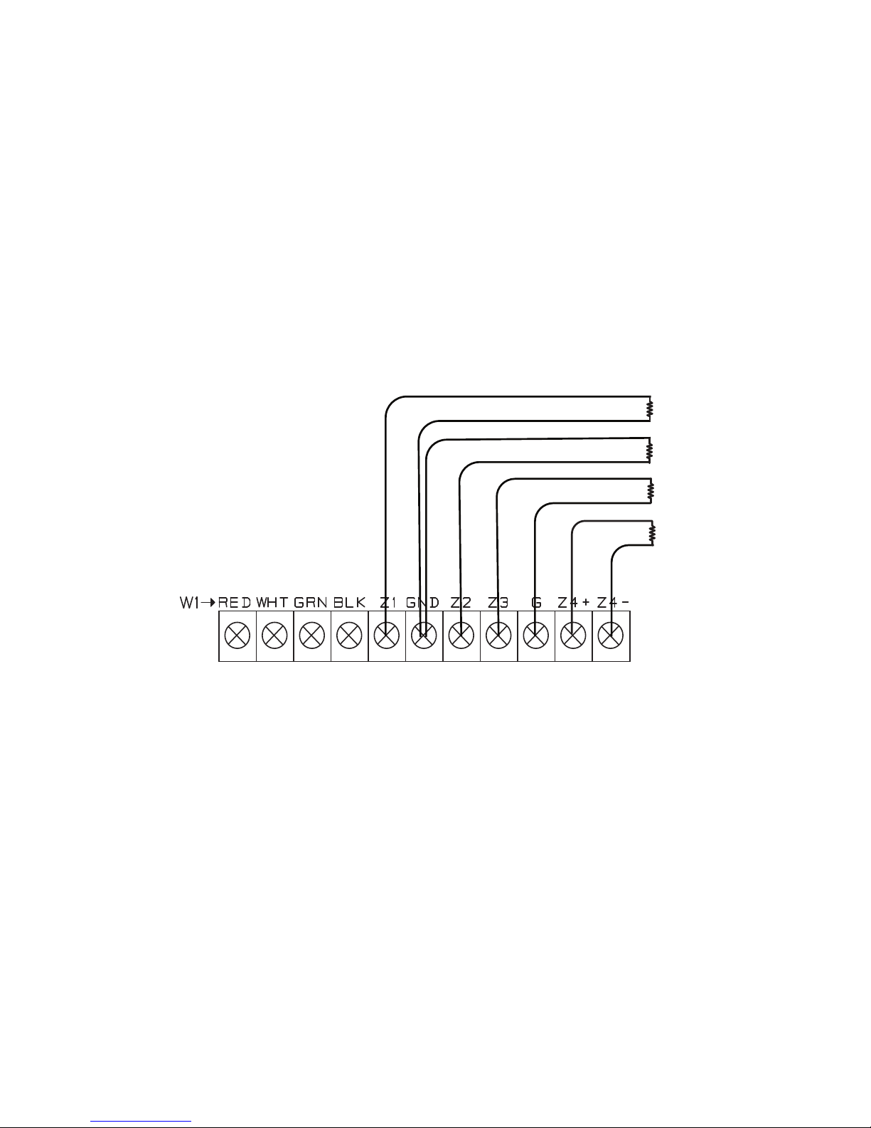
Terminals 5-9 connect grounded zones 1 through 3. These zones have a grounded side and
cannot be used for fire-initiating devices. Zones 2 and 3 can also be used for access control with
Zone 2 providing a bypass option and Zone 3 providing Request to Exit functionality. Zone 4
terminals provide a non-powered Class B, Style A zone. Use the supplied DMP Model 311 1K Ohm
End-of-Line resistors on each zone. Refer to the panel programming guide for programming
instructions. See Figure 9 for more information on wiring the zone terminals.
Auxiliary Outputs 1 & 2
The 734N controls Auxiliary Outputs 1 and 2 when the Activate Zone 2 Bypass programming option
is enabled and the Zone 2 Bypass Time is set. When the door contact (Zone 2) is opened while the
door strike is activated, the Zone 2 Bypass Time starts. If the door has not closed at the end of the
timer, Aux Output 1 is turned on and the timer starts again. If the door is still open at the end of the
second timer, Aux Output 2 is turned on. Aux Outputs 1 and 2 turn o when the door contact is
closed. Use the Model 431 Relay Harness for connection of Output 1 and Output 2.
5
WIRE THE ZONE TERMINALS
Page 15
Digital Monitoring Products, Inc. | 734N Installation and Programming Guide 11
Figure 9: 734N Zone Terminal
Wiring
Zone 1
Zone 2
Zone 3
Zone 4
1K EOL
1K EOL
1K EOL
1K EOL
Page 16

12 734N Installation and Programming Guide | Digital Monitoring Products, Inc.
Annunciator Header
The 4-pin header located on the far right of the circuit board is used to wire the Armed Status,
Remote Annunciation, and the Remote LED Control
. The open collectors supply a ground for a
maximum current of 50mA
at 30 VDC. Connect a Model 300 4-wire harness to the 4-pin header for
connection of the following indicators:
AS (Armed Status)
Armed Status provides an unsupervised switched ground for a visual or audible armed status indicator
that turns on when the burglary areas are armed, such as SYSTEM ON or ALL SYSTEM ON. Connect
the wire from the 4-wire harness to an Armed Status output.
RA (Remote Annunciation)
Remote Annunciation provides an unsupervised switched ground for a remote annunciator that turns
on when the Zone 2 Bypass timer expires.
Connect the wire from the 4-wire harness to a
remote
annunciator. The remote annunciator silences when the RA restores. The remote annunciator (RA)
switched ground operates even if the speaker is programmed not to operate.
LC (Remote LED Control)
Remote LED Control provides an unsupervised switched ground for a visual indicator that turns on
when the 734N relay activates. Connect the wire from the 4-wire harness to an LED. The LED turns
on for the duration the door strike relay is on. HID readers optionally provide a connection for LED
reader control.
Page 17

Digital Monitoring Products, Inc. | 734N Installation and Programming Guide 13
The 734N provides direct 12/24 VDC, 200 mA output to the reader on the RED terminal
connection. Figure 10 shows a reader with wire colors RED, WHT, GRN, and BLK connecting to
terminals 1, 2, 3, and 4.
The green wire carries Data Zero (D0), and the white wire carries Data One (D1). The red wire
connects 12/24 VDC, 200 mA maximum power and the black wire is ground.
The wire colors may be dierent depending on the reader being installed. Refer to the literature
provided with the reader for wire coding, wire distance, cable type (such as shielded), and other
specifications.
Card Reader LED Operation
To provide visual indication of a valid card read, the card reader can be wired to illuminate the
green LED for the duration of the door strike.
Connect the orange or brown wire to LC to have the green LED stay on for the duration of the
relay activation.
Card Reader Annunciation
Connect the yellow wire to RA to have the remote annunciator turn on anytime the panel
instructs the 734N on-board piezo to turn on.
6
CONNECT A CARD READER
(optional)
Page 18

14 734N Installation and Programming Guide | Digital Monitoring Products, Inc.
Figure 10: Card Reader Wiring
Card Reader
Red (12/24VDC)
White (Data 1)
Black (GND)
Green (Data 0)
Shield
Orange/Brown
Yellow
Page 19

Digital Monitoring Products, Inc. | 734N Installation and Programming Guide 15
ADDRESSING THE 734N
Keypad Bus Addresses
DMP XR550 Series panels use keypad bus addresses 1 through 16. XR150 Series panels can only use
keypad bus addresses 1 through 8. Each keypad bus address can accommodate 1 door output and 4
expansion zones. A 734N with an address of 2 on the keypad bus would represent Door 2 and zones
21-24. A 734N with a keypad address of 14 would represent Door 14 and zones 141-144.
AX-Bus Addresses (XR550 only)
DMP XR550 panels are capable of access control expansion using any of the five AX/LX-Bus headers
(AX/LX500, 600, 700, 800, and 900). An AX-Bus address can accommodate 1 door output and 1
expansion zone. Because the 734N has a built-in 4-zone expander, 3 extra zones must be mapped to
the 734. A 734N with an address of 501 on AX500 would represent Door 501 and zones 501-504. A
734N with an address of 505 on AX500 would represent Door 505 and zones 505-508. A 734N with
an address of 701 on AX700 would represent Door 701 and zones 701-704.
Note: Hardwired zone expanders and addressable points and modules do not communicate on
an AX-Bus. AX-Bus doors do not have programmable device or communication types and do
not have assignable display areas.
Page 20

16 734N Installation and Programming Guide | Digital Monitoring Products, Inc.
Setting the 734N Addresses
Only valid door numbers can be assigned 734N in device setup. For complete keypad and AX-Bus
address mapping, see the chart below.
Table 1: Device Addresses and 734N Zone
Numbers
DEVICE/
DOOR
ZONES
DEVICE/
DOOR
ZONES
DEVICE/
DOOR
ZONES
DEVICE/
DOOR
ZONES
DEVICE/
DOOR
ZONES
DEVICE/
DOOR
ZONES
1 11-14 501 501-504 601 601-604 701 701-704 801 801-804 901 901-904
2 21-24 505 505-508 605 605-608 705 705-708 805 805-808 905 905-908
3 31-34 509 509-512 609 609-612 709 709-712 809 809-812 909 909-912
4 41-44 513 513-516 613 613-616 713 713-716 813 813-816 913 913-916
5 51-54 517 517-520 617 617-620 717 717-720 817 817-820 917 917-920
6 61-64 521 521-524 621 621-624 721 721-724 821 821-824 921 921-924
7 7 1-74 525 525-528 625 625-628 725 725-728 825 825-828 925 925-928
8 81-84 529 529-532 629 629-632 729 729-732 829 829-832 929 929-932
9 91-94 533 533-536 633 633-636 733 733-736 833 833-836 933 933-936
10 101-104 537 537-540 637 637-640 737 737-740 837 837-840 937 937-940
11 111-114 541 541-544 641 641-644 741 741-744 841 841-844 941 941-944
12 121-124 545 545-548 645 645-648 745 745-748 845 845-848 945 945-948
13 131-134 549 549-552 649 649-652 749 749-752 849 849-852 949 949-952
14 141-144 553 553-556 653 653-656 753 753-756 853 853-856 953 953-956
15 151-154 557 557-560 657 657-660 757 757-760 857 857-860 957 957-960
16 161-164 561 561-564 661 661-664 761 761-764 861 861-864 961 961-964
Page 21

Digital Monitoring Products, Inc. | 734N Installation and Programming Guide 17
PROGRAM THE 734N
When you program a 734N, you must use a keypad connected to the 734N programming header and
set to address 1. For 12V applications, connect the keypad to the module using a Model 330 4-wire
harness. For 24V applications, connect the keypad to the module using a Model 330-24 4-wire
programming harness with in-line resistor.
Warning: Do not connect a keypad using a standard Model 330 harness if using a 24V power
supply! Damage to the keypad could occur.
You can also program the 734N from an XR150/XR550 Series panel. Initial programming of device
and communication must be performed with a keypad. Afterwards, device programming and 734N
options may be programmed from the panel’s programming interface. The panel’s programming
overrides any programming performed from a keypad connected to the 734N.
While the 734N is in programming mode, it will not be able to communicate with the panel.
RESET HEADER
To reset the module when first installing the system, short the two pins on the reset header before
applying power to the module.
To reset the module while the system is operational, short the two pins on the reset header for one or
two seconds without powering down the system.
Page 22

18 734N Installation and Programming Guide | Digital Monitoring Products, Inc.
734N PROGRAMMING
VER VVV MM/DD/YY
PROGRAM START DISPLAY
When you connect the keypad to the 734N module, the version
number and release date display. Press CMD to enter the Diagnostic
Menu. Press 6653 (PROG) then CMD to enter the Programming Menu.
INITIALIZATION OPTION
These options can set the 734N module programming memory
back to factory defaults. Press any select key or area to enter the
initialization menu.
INITIALIZE CONFIRM OPTION
After selecting YES to clear the Access Options, the 734N displays
SURE? YES NO for confirmation to clear the memory. This is a
safeguard against accidentally erasing the programming. No memory
is cleared from the programming until you answer YES to the SURE?
option. Selecting NO leaves communication options unchanged.
COMMUNICATION MENU
Press any select key or area to enter the Communication menu. Press
CMD to advance to the Access Options menu. Press the back arrow to
display the 734N Initialization menu.
ARE YOU SURE?
YES NO
734N
COMMUNICATION
INITIALIZE ALL?
NO YES
Page 23

Digital Monitoring Products, Inc. | 734N Installation and Programming Guide 19
734N DHCP
Select YES to use dynamic IP address information for the 734N IP
Address, Subnet Mask, and Gateway Address. Select NO to enter
static IP information.
734N IP ADDRESS
Enter the static IP address of the 734N if the DHCP is set to NO.
Default is 192.168.0.201.
SUBNET MASK
Enter the local subnet mask assigned to the 734N. Default is
255.255.255.0.
GATEWAY ADDRESS
Enter the local gateway address of the 734N. Default is 192.168.0.1.
PANEL IP ADDRESS
Enter the IP address of the panel. Default is 192.168.0.1.
Note: This IP address must match the address programmed in
the panel at the Local IP Address option in Network Options.
The DHCP programming in the panel must be set to NO.
734N
DHCP? NO YES
734N IP ADDRESS
192.168.0.201
SUBNET MASK
255.255.255.0
GATEWAY ADDRESS
192.168.0.1
PANEL IP ADDR
192.168.0.1
Page 24

20 734N Installation and Programming Guide | Digital Monitoring Products, Inc.
PANEL IP PORT
Enter the port number that the 734N uses to send communication
to the panel. This must be the same port that is programmed in the
734N Listen Port in Network Options programming of the panel. The
panel IP port cannot be the same as the panel network programming
port. Default is 2002.
734N PASSPHRASE
You must enter an 8-16 character alphanumeric passphrase to encrypt
communication with the panel. The 734N passphrase must match the
734N passphrase entered in Network Options programming of the
panel. The passphrase is blank by default.
ACCESS OPTIONS
Press any select key or area to enter the Access Options menu. Press
CMD to advance to the Stop options. Press the back arrow to display
the Communication menu.
PANEL IP PORT
2002
734N PASSPHRASE
734N
ACCESS OPTIONS
Page 25

Digital Monitoring Products, Inc. | 734N Installation and Programming Guide 21
ACTIVATE ZONE 2 BYPASS
Select YES to activate the zone 2 bypass operation. Selecting NO
allows standard zone operation on zone 2. The default is NO.
If the door being released by the 734N module is protected (contact
installed), a programmable bypass entry/exit timer can be provided
by connecting its contact wiring to the 734N module zone 2. When
the on-board Form C relay activates and the user opens the door
connected to zone 2, the zone is delayed for the number of seconds
programmed in ZONE 2 BYPASS TIME allowing the user to enter/exit
during an armed period.
If zone 2 does not restore (door closed) within the programmed time,
the piezo sounds every other second during the last ten seconds. If
zone 2 restores prior to the end of the programmed time, the piezo
silences. If the zone does not restore before the programmed time, the
734N ends the bypass and indicates the open or short zone condition
to the panel.
ACTIVATE ZONE 2
BYPASS? NO YES
Page 26

22 734N Installation and Programming Guide | Digital Monitoring Products, Inc.
ZONE 2 BYPASS TIME
Enter the number of seconds to elapse before the bypass timer
expires. The range is from 20-250 seconds. Press any select key or
area to enter the number of seconds. The default is 40. Figure11
shows how the bypass option works.
ZONE 2 BYPASS
TIME: 40
5 Second
Strike
40-Second Zone 2 Bypass
entry/exit timer.
10 seconds before
the bypass time expires,
the device beeps if
the door is still open.
End of
timer.
40
Seconds
A zone open/short is
indicated if the door
remains open.
Figure 11: Zone 2 Bypass Timeline
RELOCK ON ZONE 2 CHANGE
Selecting YES turns the relay o when zone 2 changes state.
Selecting NO leaves the relay on when zone 2 changes state.
Turning o the relay at Door Closed allows a long strike time to be
automatically ended and relocks the door. The default is NO.
RELOCK ON ZONE 2
CHANGE? NO YES
Page 27

Digital Monitoring Products, Inc. | 734N Installation and Programming Guide 23
ACTIVATE ZONE 3 REQUEST TO EXIT
Selecting YES activates the zone 3 Request to Exit (REX) option.
Selecting NO allows standard zone operation on zone 3. Default
setting is NO.
Connect a motion sensing device or a mechanical switch to zone 3 to
provide REX capability to the system.
When zone 3 shorts, the on-board Form C relay activates for the
programmed number of seconds. See Zone 3 REX Strike Time.
During this time, the user can open the protected door to start the
programmed zone 2 bypass entry/exit timer. After the programmed
number of seconds, the relay restores the door to its locked state
The 734N module provides a bypass-only option for REX on zone 3.
When zone 3 opens from a normal state, only a bypass occurs: the
on-board relay does not activate. This bypass-only option uses two
methods of REX.
The first REX device provides the programmed bypass entry/exit
timer. The second REX unlocks the door.
ZONE 3 REX STRIKE TIME
Enter the number of REX seconds to elapse. Range is from
5-250seconds. Press any select key or area to enter the number of
seconds. The default is 5.
ACTIVATE ZONE 3
REX? NO YES
ZN 3 REX STRIKE
TIME: 5
Page 28

24 734N Installation and Programming Guide | Digital Monitoring Products, Inc.
ACTIVATE ON-BOARD SPEAKER
Select YES to enable the onboard piezo for local annunciation, such
as alarm and trouble annunciations. Select NO to turn the speaker
o for all operations. This does not aect remote annunciator open
collector (RA) operation. The default is NO.
ACTIVATE ONBOARD
SPEAKER? NO YES
Page 29

Digital Monitoring Products, Inc. | 734N Installation and Programming Guide 25
CUSTOM CARD DEFINITIONS
CARD OPTIONS
Notice: If you see CARD FORMATS, refer to LT-1197.
Access cards contain a site code, user code, and start/stop/parity bits.
See Figure12. The starting position location and code length must be
determined and programmed into the 734NModule. Select DMP to
indicate the reader sends a 26-45 bit data string. Press the first select
key or area under DMP to select it. Default is DMP.
Select CUSTOM if using a non-DMP card.
Select ANY to allow all card reads to activate the door strike relay.
The door strike relay is activated for the length of time programmed
in ZN 3 REX TIME. No user code information is sent to the panel.
Note: When set to DMP, the 734N converts 17 bits of the 26 to
45-bit data string into a 5-digit number.
CARD OPTIONS:
DMP
CARD OPTIONS:
DMP CUSTOM ANY
01110101101101010001100111
First Bit
Received
Position = 0
Site Code
Position = 1
Length = 8
User Code
Position = 9
Length = 16
Last Bit
Received
Position = 25
Figure 12: Wiegand Data Stream Bit Location
In this example, the Wiegand
Code Length = 26 bits.
Page 30

26 734N Installation and Programming Guide | Digital Monitoring Products, Inc.
WIEGAND CODE LENGTH
When using a custom credential, enter the total number of bits to be
received in Wiegand code including parity bits. Press any select key
or area to enter a number between 1-255 to equal the number of bits.
Default is 26 bits.
SITE CODE POSITION AND LENGTH
Enter the site code start position and length in the data string. Press
select area 2 to clear the site code start position and enter a number
between 0-255. Press CMD to save. Default is 1.
Press select area 4 to clear the site code length and enter a number
between 1-16. Press CMD to save. Default is 8.
USER CODE POSITION AND LENGTH
Define the user code start bit position and length. Press select area 2
to clear the user code position and enter a number between 0-255.
Press CMD to save. Default is 9.
Press select area 4 to clear the user code length and enter a number
between 16-40. Press CMD to save. The default is the DMP value of 16.
WEIGAND CODE
LENGTH: 26
SITE CODE
POS: 1 LEN: 8
USER CODE
POS: 9 LEN: 16
Page 31

Digital Monitoring Products, Inc. | 734N Installation and Programming Guide 27
REQUIRE SITE CODE
Press the select key or area under YES to use a site code and press
CMD to view the site code entry display. Press NO to advance to
NOOF USER CODE DIGITS. Default is NO.
In addition to user code verification, door access is only granted when
any one site code programmed at the SITE CODE ENTRY option
matches the site code received in the Wiegand string.
SITE CODE
You can program up to eight three-digit site codes. The site code
range is 0-999. Any previously programmed site codes display.
Dashes represent blank site codes and indicate where digits display
on the keypad. The default for site code 1 is 127 for DMP.
Press the first select key or area to display the > character next to
site code1. Press the first select key or area again to move vertically
between site codes. Press the second select key or area to move
horizontally between site codes. When you have selected the site
code you want to change, press CMD.
REQUIRE SITE
CODE: NO YES
127 --- --- ---
--- --- --- ---
Page 32

28 734N Installation and Programming Guide | Digital Monitoring Products, Inc.
ENTER SITE CODE
Press the first select key or area to enter a site code number. Enter
your three-digit site code and press CMD to advance.
Note: A card with a site code greater than three digits cannot
be used. Use only cards with three-digit site codes.
Press the fourth select key or area to delete the site code number
displayed and return to the site code display. Repeat these steps to
change, delete, or add other site codes.
NUMBER OF USER CODE DIGITS
The 734 module recognizes user codes from 4-12digits long. Press
any select key or area to enter a user code digit length. This number
must match the user code number length being programmed in the
panel. Default is 5.
All bits are read and converted into a decimal number string. The
number string is left padded with ‘0’ if needed for long user code
lengths. When selecting ‘4’ the right digit is dropped and the next
four sent.
Example: # decoded 1234567
10 digits 0001234567
5 digits 34567
4 digits 3456
ENTER SITE CODE
127 ___ ___ DEL
NO OF USER CODE
DIGITS: 5
Page 33

Digital Monitoring Products, Inc. | 734N Installation and Programming Guide 29
NO COMMUNICATION WITH PANEL
Define the relay action when communication with the panel has not
occurred for 5seconds. Default is OFF. Press any select key or area to
change the default relay action:
Press the first select key or area to choose OFF (Relay Always O) —
The relay does not turn on when any Wiegand string is received. OFF
does not aect any REX operation. If communication is lost during a
door strike, the relay remains on for the door strike duration but turns
o at the end of the door strike timer.
Press the second select key or area to choose SITE (Accept Site
Code) — Door access is granted when the Wiegand site code string
received matches any site code programmed at SITE CODE DISPLAY.
Refer to REQUIRE SITE CODE for more information.
Press the third select key or area to choose ANY (Any Wiegand Read)
— Access is granted when any Wiegand string is received.
Press the fourth select key or area to choose ON (Relay Always On) —
The relay is always on.
Press CMD to display the next action.
Press the first select key or area to choose LAST (Keep Last State)
— The relay remains in the same state and does not change when
communication is lost.
NO COMM WITH PNL
OFF SITE ANY ON
NO COMM WITH PNL
LAST
Page 34

30 734N Installation and Programming Guide | Digital Monitoring Products, Inc.
REMOVE KEYPAD
The REMOVE KEYPAD option continually displays with no time
out while the keypad remains connected to the 734N module after
programming is finished. After five seconds, the 734N module
piezo continually sounds if the keypad remains connected and
programming is finished. Remove the keypad harness to disconnect
the keypad from the 734N module and silence the alarm.
REMOVE KEYPAD
Page 35

Digital Monitoring Products, Inc. | 734N Installation and Programming Guide 31
PUBLIC CARD FORMATS
CARD
FORMAT
WIEGAND
CODE
LENGTH
SITE
CODE
POSITION
SITE
CODE
LENGTH
USER
CODE
POSITION
USER
CODE
LENGTH
USER
CODE
DIGITS
H10301 26 BIT 26 1 8 9 16 5
H10302 37 BIT
W/FAC
37 1 16 17 19 6
H10304 37 BIT
W/O FAC
37 0 0 1 35 12
FARPOINTE
39 BIT
39 1 17 18 20 7
CORPORATE
1000 35 BIT
35 2 12 14 20 6
CORPORATE
1000 48 BIT
48 2 22 24 23 7
Page 36

32 734N Installation and Programming Guide | Digital Monitoring Products, Inc.
The 734N was designed to have minimum impact on network performance. The 734N is supervised
in the panel by exchanging two data packets every five seconds. The payload of the data packets
exchanged between the XR150/XR550 or the XR150INT/XR550INT Series and the 734N is a very
small 18 bytes. The total trac for all supervision, including network overhead, is roughly two
kilobytes per minute per 734N. This would be equivalent to a very small email message.
If required, all of the trac between the 734N(s) and the panel can be completely isolated from the
rest of the existing network by connecting all of the 734N modules and the panel to the same switch,
then connecting the switch to the remainder of the network. All trac between the 734N and the
panel would then be confined to the switch where they are connected, while still allowing the panel to
communicate with the central station through the normal network.
The security of the 734N is multi-faceted. Most importantly, the 734N is a single purpose network
device. All of the ports in the TCP/IP stack used in the 734N are disabled and allow no inbound
connections. This prevents a potential intruder from making any type of connection with the 734N
through the network. The 734N communicates with the control panel by establishing an outbound
only connection to the panel. All communication between the 734N and the control panel is
encrypted using 128-bit AES encryption. This is the same encryption standard approved and used by
the U.S. government, including the National Security Agency for encrypting secret information.
734N encryption has not been evaluated by UL.
734N NETWORK SPECIFICATIONS
Page 37

Digital Monitoring Products, Inc. | 734N Installation and Programming Guide 33
Packet Communication
• The 734N module establishes panel communication using the TCP/IP protocol.
• At start up, the 734N opens a TCP/IP connection that remains open indefinitely.
• The socket can be closed by the 734N or panel after a time-out.
• The connection is re-established by the 734N after the time-out.
• A pair of supervision packets are sent every 5 seconds.
- The payload for each packet is 18 bytes and the total trac, including overhead, is
approximately 2 kilobytes per minute for each 734N.
- Non-Supervision messages have a payload range of 18-50 bytes.
Page 38

34 734N Installation and Programming Guide | Digital Monitoring Products, Inc.
COMPLIANCE LISTING SPECIFICATIONS
UL ACCESS CONTROL
The access relay must be configured as fail-safe or fail-secure as determined by the local Authority
Having Jurisdiction (AHJ). This system is not intended to be used in place of listed panic hardware.
For listed installations, the 734N or 734N-POE must be installed within the protected area.
The power supply must be a listed commercial burglary/household fire, power limited, Class 2 with
a compatible voltage range for the product. The 734N requires a 12 or 24 VDC power source. The
734N-POE can be powered by a 12 or 24 VDC or UL 294 listed POE switch.
For listed installations, the 734N-POE must be installed inside a UL listed DMP metal enclosure such
as a Model350. Refer to Mount the Device for mounting instructions.
Allow 4 hours for standby power to meet UL listed standards.
ULC COMMERCIAL BURGLARY (XR150/XR550 SERIES PANELS)
When using the zones of the 734N in a listed application, place the module in a listed enclosure and
connect a DMP Model 307 Clip-on Tamper Switch to the enclosure programmed as a 24-Hour zone.
The 734N Access Control features have not been investigated by ULC.
The 734N zones can be used in a Low Risk application. For Medium or High Risk applications, refer to
the Dual Zone Protection diagram in the XR150/XR550 Canadian installation guide.
Page 39

Digital Monitoring Products, Inc. | 734N Installation and Programming Guide 35
CERTIFICATIONS
FCC Part 15
California State Fire Marshal (CSFM)
NIST AES Algorithm Certificate #1937
UNDERWRITERS LABORATORY (UL LISTED)
734N
ANSI/UL 294 Access Control System Units
Level I Destructive Attack and Line Security
Level IV Endurance and Standby Power
ANSI/UL 609 Local Burglar Alarm Units And Systems
ANSI/UL 1076 Proprietary Burglar Alarm Units And Systems
ANSI/UL 1023 Household Burglar-Alarm System Units
ANSI/UL 1610 Central Station Burglar-Alarm Units
ULC S304 Central And Monitoring Station Burglar Alarm
ULC/ORD-C1076 Proprietary Burglar
ULC Subject-C1023 Household Burglar
Page 40

36 734N Installation and Programming Guide | Digital Monitoring Products, Inc.
734N-POE
ANSI/UL 294 Access Control System Units
Level I Destructive Attack and Line Security
Level IV Endurance and Standby Power
ANSI/UL 609 Local Burglar Alarm Units And Systems
ANSI/UL 1076 Proprietary Burglar Alarm Units And Systems
ANSI/UL 1610 Central Station Burglar-Alarm Units
Page 41

Digital Monitoring Products, Inc. | 734N Installation and Programming Guide 37
INTERNATIONAL CERTIFICATIONS
Security Grade: 3
Environmental Class: II
INTERTEK (ETL) LISTED*
EN 50130-4 EMC Product Family Standard: Immunity
Requirements for Componenets of Fire,
Intruder and Social Alarm Systems
EN 50130-5 Environmental Standards
EN 50131-1:2006+A1 Intrusion and Hold-up Systems
EN 50131-3:2009 Control and Indicating Equipment
EN 50133-1:1997 Access Control Systems
EN 61000-3-2 Limits - Limits for Harmonic Current Emissions (Equip.Input Current
up to and Including 16 A per Phase) Includes A1 & A2 July 1, 2009
EN 61000-3-3 Limitations of Voltage Fluctuations & Flicker in Low-Voltage Supply
Systems for Equip with Rated Current Less Than or Equal to 16 A per
Phase & Not Subject to Conditional Connection
EN 61000-6-4 Generic Standards - Emissions Standard for Industrial Environments
*These listings are for the 734N only. The 734N-POE has not been evaluated for International
Certifications.
EXPORT CONTROL
The 734N uses AES encryption and any export beyond the United States must be in accordance with
Export Administration Regulations.
Page 42

38 734N Installation and Programming Guide | Digital Monitoring Products, Inc.
PRODUCT SPECIFICATIONS
Primary Power 8.5 VDC to 28.5 VDC if 12/24 VDC
Current Draw
Standby 346mA at 12 VDC (includes 200mA for proximity reader)
+1.6 mA per active zone
Alarm 348 mA at 12 VDC (includes 200mA for proximity reader)
+10 mA with Annunciator ON
+2 mA per faulted zone
Form C Relay 35 mA at 12/24 VDC
When powered from POE
Standby 243 mA (includes 200mA for proximity reader)
+1.6 mA per active zone
Alarm 273mA (includes 200mA for proximity reader)
+10 mA with Annunciator ON
+2 mA per faulted zone
Page 43

Digital Monitoring Products, Inc. | 734N Installation and Programming Guide 39
Output Voltage (POE) 12 VDC
Maximum Power Draw (POE) 12.95 W
Available Output Current 750 mA
Zones 5 VDC, 2 mA max
Dimensions 4.5W x 2.75H x 1.75D in
11.43W x 7H x 4.45D cm
Weight 8 oz .23 kg
Page 44

40 734N Installation and Programming Guide | Digital Monitoring Products, Inc.
READERS AND CREDENTIALS
125 KHZ PROXIMITY READERS
P-300 CASCADE PROXIMITY
READER
P-500 ALPS PROXIMITY READER
P-640 PATAGONIA PROXIMITY
READER WITH KEYPAD
MP-5365 MINIPROX™ PROXIMITY
READER
MX-5375 MAXIPROX® PROXIMITY
READER
PP-6005B PROXPOINT® PLUS
PROXIMITY READER
PP-5355 PROXPRO PROXIMITY
READER WITH KEYPAD
PR-5455 PROXPRO® II PROXIMITY
READER
TL-5395 THINLINE II® PROXIMITY
READER
125 KHZ PROXIMITY CREDENTIALS
PSC-1 STANDARD LIGHT
PROXIMITY CARD
PSK-3 PROXIMITY KEY
RING TAG
PSM-2P ISO IMAGEABLE
PROXIMITY CARD
1306 PROX PATCH™
1326 PROXCARD II®
CARD
1346 PROXKEY III®
ACCESS DEVICE
1351 PROXPASS®
1386 ISOPROX II® CARD
Page 45

Digital Monitoring Products, Inc. | 734N Installation and Programming Guide 41
13.56 MHZ SMARTCARD READERS*
DELTA3 FARPOINTE SMARTCARD
READER
DELTA5 FARPOINTE SMARTCARD
READER
DELTA5.3 FARPOINTE SMARTCARD
READER
DELTA6.4 FARPOINTE SMARTCARD
READER
13.56 MHZ SMARTCARD CREDENTIALS*
DC1-1 FARPOINTE CLAMSHELL
SMARTCARD
DM1-3 FARPOINTE IMAGEABLE
SMARTCARD
DE2 FARPOINTE MIFARE®
DESFIRE® EV1
SMARTCARD
DK1-3 FARPOINTE KEY FOB
SMARTCARD
*Delta Proximity Readers and Credentials not evaluated by UL.
Page 46

Page 47

Page 48

LT-1197C 18512 1.04 © 2018 Digital Monitoring Products, Inc.
 Loading...