

Page 1
g
INSTALLATION SHEET
692 Security Command™ Keypad
Description
The DMP 692 Security Command LED keypad for the XRSuper6, XR20, and XR40 Command Processor™ Panels provides
three 2-button Panic keys, three system status LEDs, three armed status LEDs, and ten zone LEDs. The 692 Keypad
also contains a backlit keyboard with easy-to-read lettering, COMMAND key arming, and an internal alert buzzer.
The 692 Keypad is designed for use with Home/Sleep/Away and All/Perimeter systems. The 692 Keypad does not
support all of the functions of an Area system and does not provide visual annunciation above zone 10.
Removing the Base
The 692 is made up of two parts: the front which contains the circuit board and other components, and the base. To
remove the base, insert a ß at screwdriver into one of the openings on the bottom and gently twist it while pulling
the halves apart as shown in Figure 1. Repeat with the other opening.
Figure 1: Remove Keypad Base
Inserting the Reference Card
A reference card is supplied with the 692 Keypad. The reference card is provided to assist the users when operating
their security systems. Write the zone descriptions on the front of the card. Slide the card in the back of the base
before installing the keypad. Refer to Figure 2 for reference card installation.
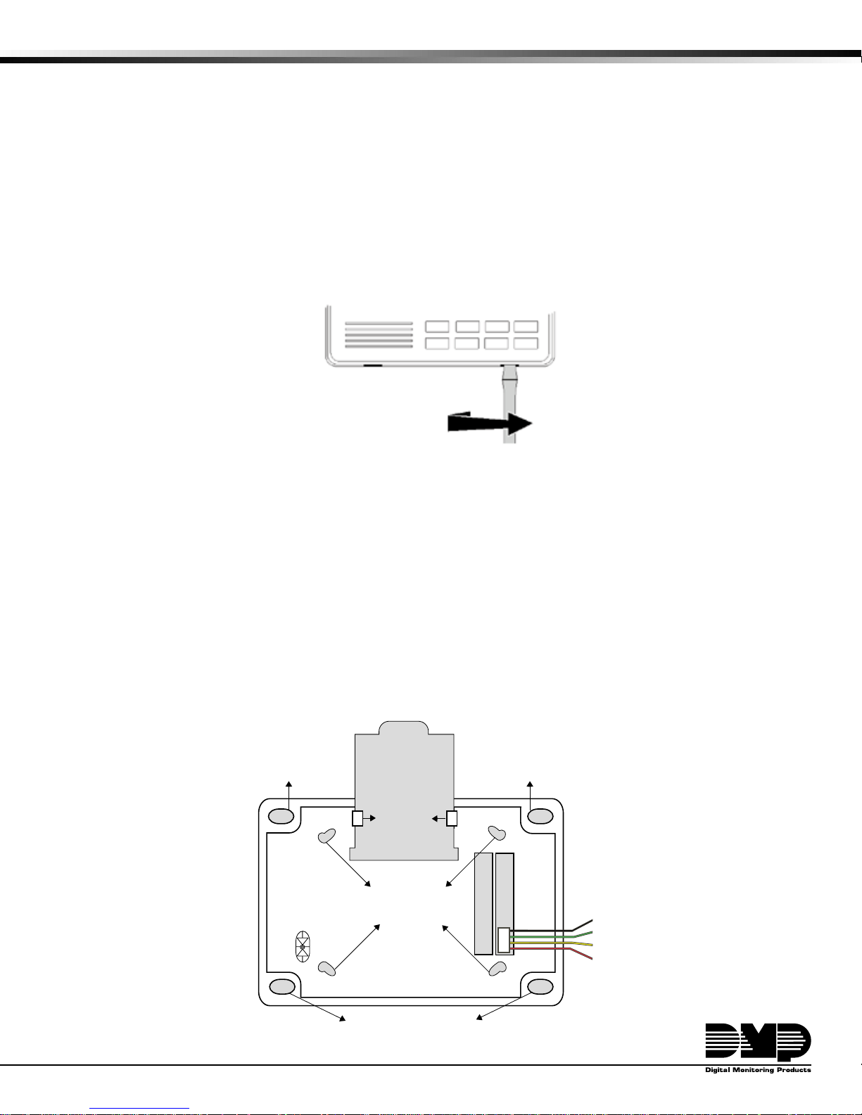
Mounting the 692 Keypad
The 692 Keypad is designed to easily install on any 4-square box, 3-gang switch box, 695 and 696 backbox, or on any
ß at surface. Figure 2 shows the mounting hole locations on the keypad base.
Wiring the 692 Keypad
The 692 Keypad is supplied with a single 4-wire harness for connection to the panel keypad data bus wiring. Connect
the 4-wire harness to the back of the PCB as shown. Then connect the wires to the panel terminals 7, 8, 9, and
10. In Figure 2, the numbers to the left of each wire color and description represent the terminals where the wires
connect.
Reference Card
Surface and Backbox
Mounting Holes
Guide Tabs
Surface and Backbox
Mounting Holes
Combined 4-square
and 3-gang switch box
Mounting Holes
Back of 692
Keypad Base
Surface and Backbox
Mountin
Holes
Figure 2: 692 Keypad Back
Black - 10
Green - 9
Yellow - 8
Red - 7
Page 2

Wiring SpeciÞ cations
When planning a keypad bus installation, keep in mind the following four speciÞ cations:
1. DMP recommends using 18 or 22-gauge unshielded wire for all keypad and LX-Bus circuits. Do Not use
twisted pair or shielded wire for LX-Bus and keypad bus data circuits. To maintain auxiliary power integrity
when using 22-gauge wire do not exceed 500 feet. When using 18-gauge wire do not exceed 1,000 feet.
Install an additional power supply to increase the wire length or add devices.
2. Maximum distance for any one circuit (length of wire) is 2,500 feet regardless of the wire gauge. This
distance can be in the form of one long wire run or multiple branches with all wiring totaling no more than
2,500 feet. As wire distance from the panel increases, DC voltage on the wire decreases.
3. Maximum number of devices per 2,500 feet circuit is 40.
Note: Each panel allows a speciÞ c number of supervised keypads. Add additional keypads in the
unsupervised mode. Refer to the panel installation guide for the speciÞ c number of supervised keypads
allowed.
4. Maximum voltage drop between the panel (or auxiliary power supply) and any device is 2.0 VDC. If the
voltage at any device is less than the required level, add an auxiliary power supply at the end of the circuit.
When voltage is too low, the devices cannot operate properly.
Refer to the 710 Module Installation Sheet (LT-0310) for more information. Also see the LX-Bus/Keypad Bus Wiring
Application Note (LT-2031).
Additional Power Supply
If current draw for all keypads connected to the panel exceeds the panel output, you can provide additional current
by adding an auxiliary power supply. If the voltage drop exceeds 2.0 VDC, an auxiliary power supply is also needed.
2-Button Panic Keys
The 692 Keypad Panic key function lets users easily send a Panic, Emergency, or Fire report to the central station.
The user must press and hold the two Select keys for two seconds until they hear a beep from the keypad. At the
beep, the panel sends an alarm report to the central station with the following zone numbers: 19 - Panic, 29 - nonmedical Emergency, and 39 - Fire.
Note: If a panic is initiated using the Panic Keys, the actual panic signal is reported as address 8.
The Panic key function is active as soon as you apply power to the keypad. If the owner intends to use the Panic
keys, install the supplied icon label below the top row Select keys.
Buzzer Operation
Each time a user presses a key on the 692, the buzzer emits a short tone. After the user performs a successful
keypad operation, such as disarming the system, the buzzer emits a 1/2 second tone. If the operation is not
successful, the buzzer emits four short tones. This alerts the user to perform the function again.
During trouble conditions, the keypad emits a steady tone to alert the user. Pressing any key silences the buzzer.
Keyboard Backlighting
The keyboard on the 692 lights anytime a key is pressed or the alert buzzer sounds making it easy for users in
darkened rooms to enter their code or perform a command function.
984 COMMAND
Enter 984 + COMMAND to allow the panel to seize the telephone line for a remote connect from Remote Link™. After
pressing the COMMAND key, the panel immediately seizes the line.
Enter 984 + COMMAND plus up to 15 digits for the phone number to contact the Remote Link™ program.
SpeciÞ cations
Operating Voltage 8.5 to 15 VDC
Operating Current 30mA in Standby
70mA in alarm
Dimensions 6.75" x 5.0" H x 1.0" D
800-641-4282
www.dmp.com
Made in the USA
Accessories
695 Conduit Backbox
696 Keypad Backbox
699 Keypad Deskstand
INTRUSION • FIRE • ACCESS • NETWORKS
2500 North Partnership Boulevard
SpringÞ eld, Missouri 65803-8877
LT-0269 (2/04) © 2004 Digital Monitoring Products, Inc.
 Loading...