

Page 1
INSTALLATION SHEET
481 Zone Expansion Interface Card
Description
The 481 Expansion Interface Card allows you to expand the XR200 panel by up to 100 additional hardwire zones. The
481 provides one 4-wire LX-Bus™ connection that supports combinations of the 711, 714, and 715 Zone Expanders,
716 Output Expanders, and 717 Graphic Annunciator Modules.
You can also connect the single point 5845LX ShatterPro Glassbreak Detector, 6155LX SharpShooter PIR, 521LX/
521LXT Smoke Detector, and the 867 Addressable Notification Module to the LX-Bus.
The XR200 panel can support up to 200 zones of protection on multiple LX-Buses when using the 460 Interface
Adaptor Card and two 481 Expansion Interface Cards. The 481 can also be used with the 462N, 462FM, 462P, and 472
interface cards.
Installation Safety
Ground Yourself Before Handling the Panel! Touch any grounded metal, such as the enclosure, before
touching the panel to discharge static.
Remove All Power From the Panel! Remove all AC and Battery power from the panel before installing
or connecting any modules, cards, or wires to the panel.
Installing the 481 Card
1. Remove AC and battery power from the XR200 panel before installing the 481 card.
2. Align the 50 pin connector of the 481 with the J6 connector on the XR200 panel.
3. Press the 481 onto the J6 connector while applying even pressure to both sides of the board.
4. Connect the LX-Bus wiring to the harness supplied with the module.
5. Insert the harness connector into the LX-Bus header on the bottom of the 481 card.
6. Restore power to the panel.
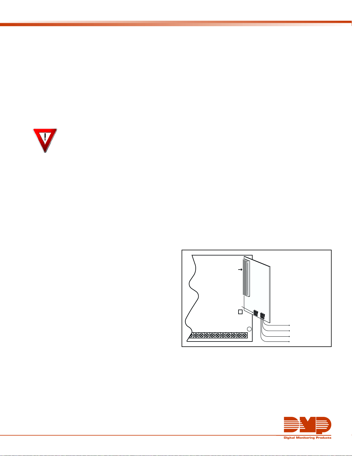
Connecting Devices to the 481
The 481 card contains a 4-wire LX-Bus harness to which you connect the hardwire LX-Bus devices detailed above. The
harness plugs into a 4-pin header located on the bottom of the 481 card. Connect the 4-wire LX-Bus wiring to the
harness as shown in Figure 1. All four wires are used.
Note: Do not use shielded wire when using the LX-Bus.
Wiring Specifications
When planning an LX-Bus installation, keep in mind the
following four specifications:
1. You can install individual keypads on wire runs of
up to 500 feet using 22 gauge wire or up to 1,000
feet using 18 gauge wire. To increase the wire
length or add additional devices, a power supply is
required.
2. Maximum distance for any one keypad bus circuit
(length of wire) is 2,500 feet regardless of the
gauge of wire. This distance can be in the form of
one long wire run or multiple branches with all
wiring totaling no more than 2,500 feet.
3. Maximum number of devices per 2,500 feet circuit is 40. (Note: Each panel allows a specific number of
supervised keypads. Additional keypads can be added in the unsupervised mode. Refer to the panel’s
installation guide for the specific number of supervised keypads that are allowed.)
4. Maximum voltage drop between the panel (or auxiliary power supply) and any device is 2.0 VDC. If the voltage
at any device is less than the required level, an auxiliary power supply should be added at the end of the
circuit.
Refer to the 710 Module Installation Sheet (LT-0310) for more information. Also see the LX-Bus/Keypad Bus Wiring
Application Note (LT-2031).
18
J6 Interface Card
Connector
Zone Expansion
Harness Connectors
Z6
Z7
GND
Z5
20
22 23
19
21
GND
Z8 Z9+
24
Z9-
26 27
25
Z10+
Z10-
28
481 Zone
Expansion
Interface
Card
B
A
Figure 1: 481 Interface Card Wiring
To LX-Bus Modules
Red—Auxiliary Power
Yel lo w—Data In
Green—Data Out
Black—Ground
Page 2
Installing Multiple Expansion Devices
Smoke and Heat Detector
Strobe
Circuits
S
S
S
H
715 Zone
Expander
Roll-Up
Doors
H
H
Heat Detectors
H
5845LX
Glassbreak
Detectors
Exterior
Lighting
Window Contact
716 Output
(relay)
Expander
717 Graphic
Annunciator
Module
1.5 Amps
Bell Output
Smoke Detector
Output Terminal 11
714 Zone
Expander
H
Window
H
Contact
Heat Detectors
481 Expansion
Interface Card
LX-Bus
FIRE
Manual
Door
Pull
Contact
TM
PIR
6155LX PIR
Fire Bell
Manual Pull
FIRE
Figure 2: XR200 panel with 481 card and LX-Bus expansion devices.
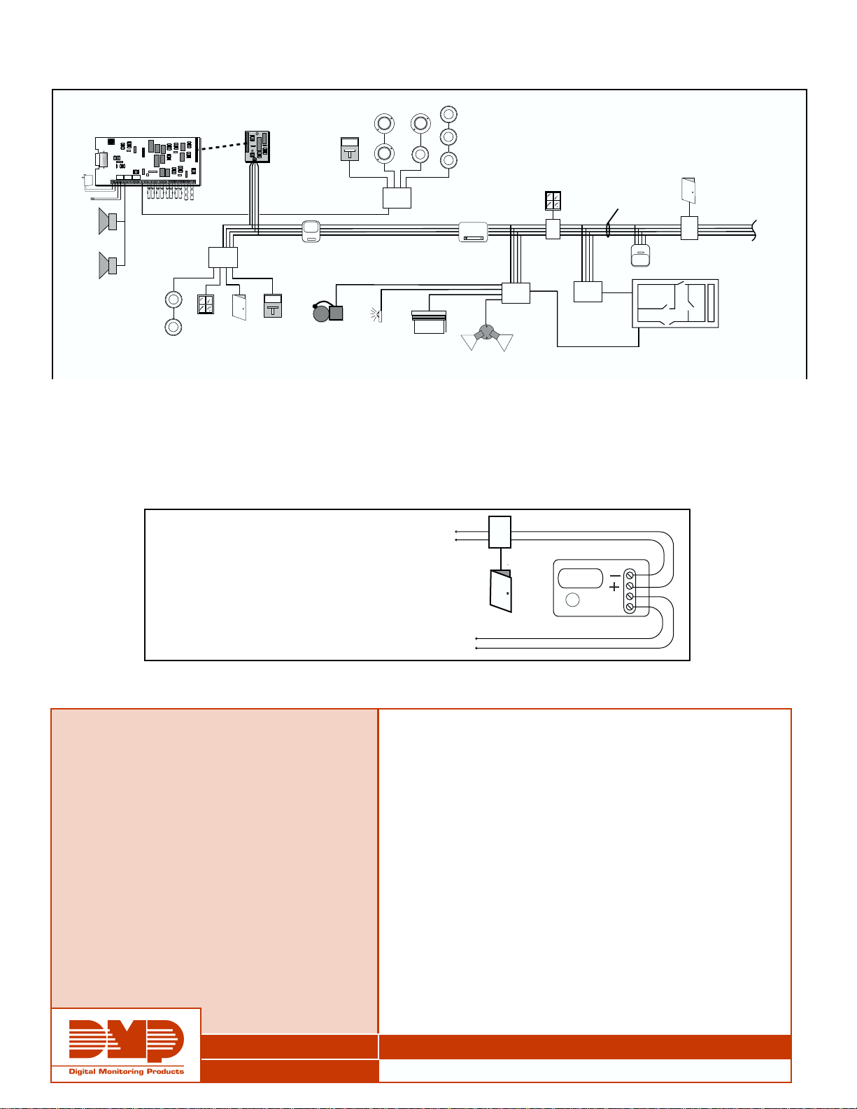
Tips for Using an Optional Power Supply
• Locate auxiliary power supply at far end of LX-Bus wire run.
• Connect the negative wire from the power supply to the common wire of the LX-Bus.
• Never use the panel's transformer for the power supply.
Single 4-wire
cable
PIR
6155LX PIR
*
*
Graphic Annunciator
Door Contact
Up to 100 zones and relays
can be added to the LX-Bus.
711 Zone Expander
*
*
*
*
*
*
*
**
*
*
*
*
To LX-Bus™ wiring. Do NOT connect the
positive wire from the power supply to the
postitive (red) wire from the panel.
To AC Transformer. Do NOT use the panel's
transformer. Connect the negative terminal of
the power supply to the common terminal (10)
of the panel.
Figure 3: Power supply at end of LX-Bus.
SPECIFICATIONS
Primary Power 12 VDC from panel
Current Draw 15mA
Dimensions 2.25” W x 5.25” H
Panel Compatibility XR200, XR200-485, and
XR2400F
ACCESSORIES
460 Interface Adaptor Card
708 Bus Extender Modules
710 Bus Splitter/Repeater Module
710F Fire Bus Splitter/Repeater module
711 Single-Zone Expander Module
711E Single-Zone Expander Module
714 Four-Zone Expander Module
711 Zone Expander
Door
Contact
AC
DMP 505-12 Power Supply
714-8 Eight-Zone Expander Module
714-16 Sixteen-Zone Expander Module
714-18T Four-Zone Expander Module with Terminal Block
714-19T Four-Zone Expander Module with Terminal Block, EOL
714-X Four-Zone Expander Module
715 Four-Zone Expander Module
715-8 Eight-Zone Expander Module
715-16 Sixteen-Zone Expander Module
715-18T Four-Zone Expander Module with Terminal Block
715-19T Four-Zone Expander Module with Terminal Block, EOL
715-20T Terminal Board
716 Four-Output Expander Module
717 Graphic Annunciator Module (20 Outputs)
725 24 VDC Four-Zone Expander (use with 710F)
736P Radionics™ Popit Interface Module
738A Ademco™ Interface Module
800 - 641 - 4282
WWW.DMP.COM
CITYWIDE, NATIONWIDE, WORLDWIDE
2500 N. PARTNERSHIP BLVD., SPRINGFIELD, MISSOURI 65803-8877
LT-0199 (4/02) Copyright © 2002 Digital Monitoring Products
 Loading...