

DMP Electronics 472 Inovonics Installation Manual
INSTALLATION GUIDE
472 Inovonics™ 900MHz Interface Card
Description
The 472 Inovonics™ 900MHz Interface Card allows one or two Inovonics FA400-DMP Remote Receivers to be connected
to the XR500 Series Command Processor™ panel. FA400-DMP Receivers allow up to 200 panel expansion zones using
Inovonics FA series wireless transmitters.
The 472 card also provides a 4-wire LX-Bus™ that supports combinations of the 711, 714, and 715 Zone Expanders,
716 Output Expanders, 717 Graphic Annunciator Modules, and the full range of LX series single-point detectors.
When using the 472 card 4-wire LX-Bus™ there are 100 hardwire zones and 100 wireless zones available.
Note: When using a 472 card in combination with a 461 Interface Adaptor Card on XR500 Series panels, a Model 350
or 352 Enclosure is required.
Installing the 472 Inovonics 900MHz Interface Card
Note: If you are programming a new panel, be sure to enter Programming mode and select Initialize All before
installing the 472 card.
1. Important! Remove AC and battery power from the panel before installing the 472 card.
2. Align the 472 Card 50-pin connector with the panel J6 Expansion Connector.
3. Evenly press the 472 into the J6 connector to seat it into place.
LX-Bus Wiring
The 472 provides one 4-wire harness to connect LX-Bus devices, such as zone expansion modules, detectors, and
keypads. Do not connect the 4 wires from the harness to the panel terminals. Also, do not use shielded wire when
connecting LX-Bus devices.
Locating the FA400-DMP Receiver
Prior to installation, DMP recommends using the FA715 Survey Kit to determine transmission characteristics at the
application site. The survey kit helps determine optimal location of the FA400-DMP and FA series transmitters.
Generally, it is advisable to install the receiver in a spot central to ALL wireless transmitters. To solve range or
transmission problems, install FA575 Real-Time Repeaters as needed.
Note: The receivers must be mounted outside of the panel enclosure to ensure optimum signal reception. The
FA400-DMP can be mounted next to the panel or at a distance of up to 150 feet per receiver on 22 gauge wire.
If possible, install receivers away from large metal objects. Mounting the receiver on metal surfaces impairs
performance.
For Commercial Burglary UL listed systems, the FA400-DMP Receiver must be mounted within three feet of the
control unit with no intervening walls or barriers.
Connecting the FA400-DMP Receiver
The Inovonics FA400-DMP Receiver contains an internal 3-position terminal strip. To connect an FA400-DMP to the
472 card, use the 472 wire harness and following the color guide in the table below. Only three of the four wires are
used: The Yellow wire is not used. Do NOT use shielded wire.
472
Harness
Red connects to VS
Black connects to GND
Green connects to OUT
Yellow is not used. —
FA400-DMP
Receiver Terminals
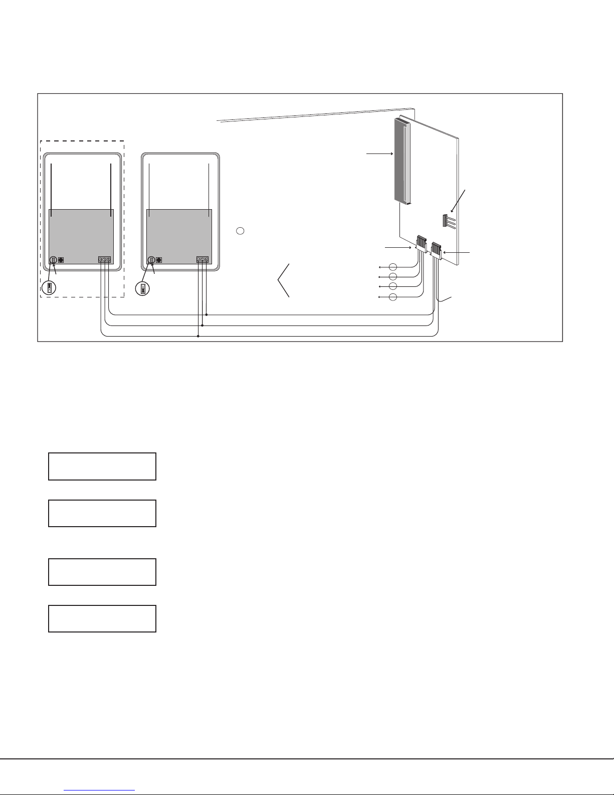
Do not use the receiver without a jumper installed on the three-pin receiver jumper. When using one receiver install
the jumper on Receiver 1 position. When using an optional second receiver, set receiver jumpers to Receiver 1
position and Receiver 2 positions, respectively. See Figure 1. The receivers should be mounted at least three feet
apart.
XR500 Series Command Processor™ Panel
Inovonics FA400-DMP
Optional Second Receiver
Wireless Receiver(s)
J6 Expansion
Connector
Max total distance for wiring on
472
Inovonics
900MHz
Interface
Card
Transmitter
Programming
Connector
one LX-Bus™ circuit is 2,500 feet.
s
= Supervised
FA400-DMP
Wireless Receiver
Connector
Reset Reset
Receiver Jumper
Receiver 2 Position
1 2
Note: Do Not use
receiver without a jumper.
Receiver Jumper
1 2
Receiver 1 Position
To LX-Bus
Modules
OUT - Green
GND - Black
VS - Red
LX-Bus™ Harness
Black - Aux. Common
Green - Serial Data Out
Yellow - Serial Data In
Red - Aux. Positive
Green
Black
Red
s
s
s
s
* Yellow Wire is not used
for 472 to FA400-DMP
connection.
Figure 1: 472 Inovonics 900MHz Interface Card Wiring
Programming Wireless Zones
After programming the House Code to 99 in System Options and the zone type and area assignment for the wireless
zone, program the operating parameters for the wireless transmitters. At the NEXT ZONE? prompt, select NO
to display the wireless zone options. The transmitters connect to the 472 for programming after all zones are
programmed. See Programming Wireless Transmitters.
Note: A panel account number must be programmed before programming the wireless transmitters.
WIRELESS YES NO
CHECK IN TM: 60
NONE 10 30 60
INT CONT NO YES
EOL NO YES
Wireless
Select YES if you are programming a wireless zone. Press the COMMAND key to
continue wireless programming.
Check-in Time
You can set wireless transmitters to check in automatically every 10, 30, or 60 seconds
or not at all. To change the 60 second default, press any top row Select key to display
NONE 10 30 60. Press the Select key under the desired check-in time for this zone.
Internal Contact
Select YES to use an internal contact on the wireless transmitter. Select NO to use an
external contact. When NO, the following two prompts display.
End-of-Line
Select YES to supervise an external contact connected to the wireless transmitter.
At the contact, install a 2.2k Ohm End-of-Line resistor in parallel for Normally Open
contacts and in series for Normally Closed contacts.
Digital Monitoring Products 472 Installation Guide
2
 Loading...