

Page 1
INSTALLATION SHEET
463C CDMA Cellular Communicator
Description
The 463C CDMA Cellular Communicator provides a fully supervised alarm communication path over the CDMA network. The
463C is installed in the panel J6 Interface Card connection or a 461 Interface Adaptor card and powered by the panel so no
additional enclosure, power supply or battery back-up is needed.
What is Included
The 463C includes the following:
• One Model 463C
• One Model 381-2 18-inch Coax cable with SMA connector
• One Model 300 4-Wire LX-Bus harness
• One Model 383 Rubber Duck Antenna
Compatibility
The 463C is compatible with the XR100/XR500 Series panels using software Version 211 or higher.
Installation Safety
Ground Yourself Before Handling the Panel! To discharge static, touch any grounded metal, such as the enclosure, before
touching the panel.
Remove All Power From the Panel! Remove all AC and
Battery power from the panel before installing or
connecting any modules, cards, or wires to the panel.
SMA
Connector
Nut
Antenna
Connector
Washers
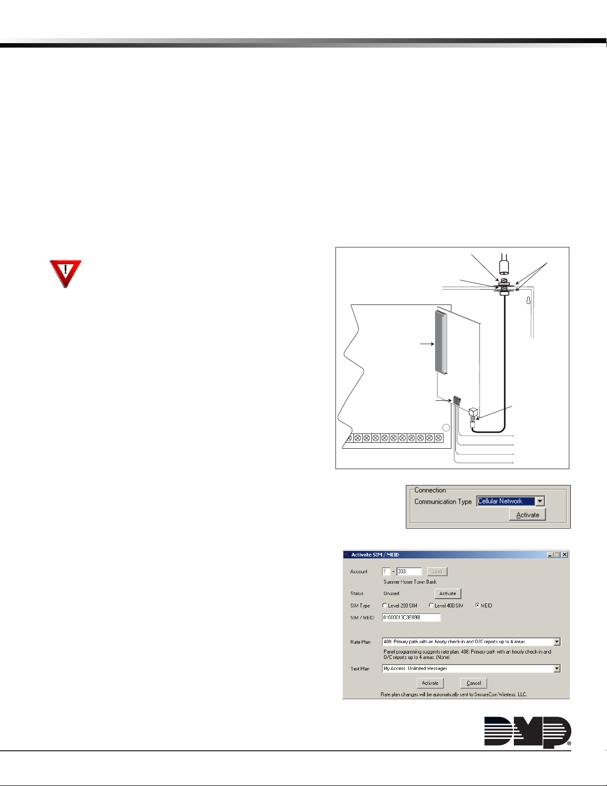
Installing the 463C
Align the 463C card 50 pin connector with the J6 connector and
XR100/XR500
Panel
press the card onto the connector while applying even pressure to
both sides of the board. See Figure 1.
Connecting the Antenna
J6 Interface Card
Connector
1. Position one of the supplied washers onto the SMA connector
and push the threaded end through an enclosure knockout.
2. Position the second washer onto the threaded end extending
through the knockout and secure the nut.
3. Attach the included 383C Antenna to the SMA connector.
See Figure 1.
As an alternative, the antenna coax can be connected directly
to the 463C SMA connector when the coax enters the enclosure
Z6
Z7
GND
GND
Z5
20
22 232425
19
18
21
via conduit.
LX-Bus™ Expansion Capability
Figure 1: Install and connect the 463C and Antenna
The 463C card also provides a 4-wire LX-Bus™ for the addition of
any combination of 100 protection zones and 100 relay outputs. Insert the harness
connector into the 4-pin LX-Bus header on the bottom of the 463C Interface Card.
Note: Do not use shielded wire when using the LX-Bus. Do not connect the wires
from the 463C to panel terminals or the panel J22 header.
Programming/Activation
Cellular Service is required before using the 463C for signal
transmission. The 463C comes ready for activation with SecureCom
Wireless, LLC.
1. In Remote Link panel communication programming, select
Cellular Network as the Communication Type and select the
Activate button. See Figure 2.
A. In the Activate SIM/MEID window, enter the MEID number,
found on the 463C label.
B. Select the rate plan for the 463C. See Figure 3.
C. Select the Activate button at the bottom of the window.
2. After the 463C is installed at the site, use a keypad and enter
the XR100/XR500 panel's Diagnostics menu (2313).
A. Select ACTIVATE CELL by pressing a top row Select Key.
B. Press the button beneath YES on the next screen to activate
the device.
Note: The ACTIVATE CELL prompt will only display if a CDMA modem is installed.
Figure 3: Remote Link Activation
463C
Interface
Zone Expansion
Harness Connector
Z8 Z9+
Z9-
Z10+
26 27
Card
SIM
Card
B
Z10-
28
Coax Cable
from 463C
SMA
Connector
To LX-Bus
Modules
Red—Auxiliary Power
Yellow—Data In
Green—Data Out
Black—Ground
Figure 2: Remote Link Activation
Page 2
Diagnostics
The XR100/XR500 Series panels provide a Diagnostics function to test the Communication integrity and Cellular Signal
strength of the 463C. To use Diagnostics, reset the panel, enter the Diagnostics code 2313 (DIAG), and press COMMAND.
Communication Status
Select COMM STATUS from the Diagnostics menu. The XR100/XR500 Series panels test the 463C for the following items:
• 463C Installed • Cellular Tower Detected • 463C Registered • Communication Path Integrity
• 463C Operating • NOC Success • 463C Identied
Cellular Signal
-XX dBm
SIGNAL:
▐▐▐▐▐▐▐
Select CELL SIGNAL from the Diagnostics menu. The XR100/XR500 Series panels test and indicates the
strength of the signal using a bar display. One bar indicating a weak signal. Seven bars indicating a
strong signal. The X's represent the numerical value of the cell signal strength in -dBm.
Wiring Specications for LX-Bus
When planning an LX-Bus installation, keep in mind the following specications:
1. DMP recommends using 18 or 22-gauge unshielded wire for all keypad and LX-Bus circuits. Do Not use twisted pair or
shielded wire for LX-Bus and keypad bus data circuits. To maintain auxiliary power integrity when using 22-gauge wire
do not exceed 500 feet. When using 18-gauge wire do not exceed 1,000 feet. Install an additional power supply to
increase the wire length or add devices.
2. Maximum distance for any one circuit (length of wire) is 2,500 feet regardless of the wire gauge. This distance can be
in the form of one long wire run or multiple branches with all wiring totaling no more than 2,500 feet. As wire distance
from the panel increases, DC voltage on the wire decreases.
3. Maximum number of devices per 2,500 feet circuit is 40.
Note: Each panel allows a specic number of supervised keypads. Add additional keypads in the unsupervised mode.
Refer to the panel installation guide for specic number of supervised keypads allowed.
4.
Maximum voltage drop between the panel (or auxiliary power supply) and any device is 2.0 VDC. If the voltage at any device
is less than the required level, add an auxiliary power supply at the end of the circuit. When voltage is too low, the devices
cannot operate properly. For additional information refer to the LX-Bus/Keypad Bus Wiring Application Note (LT-2031).
FCC Information
This device complies with Part 15 of the FCC Rules. Afx the included FCC label to the exterior of the panel enclosure in plain sight.
Operation is subject to the following two conditions:
(1) This device may not cause harmful interference, and
(2) this device must accept any interference received, including interference that may cause undesired operation.
Changes or modications made by the user and not expressly approved by the party responsible for compliance could void the user’s
authority to operate the equipment.
NOTE: This equipment has been tested and found to comply with the limits for a Class B digital device, pursuant to part 15 of the
FCC Rules. These limits are designed to provide reasonable protection against harmful interference in a residential installation. This
equipment generates, uses and can radiate radio frequency energy and, if not installed and used in accordance with the instructions,
may cause harmful interference to radio communications. However, there is no guarantee that interference will not occur in a particular
installation. If this equipment does cause harmful interference to radio or television reception, which can be determined by turning the
equipment off and on, the user is encouraged to try to correct the interference by one or more of the following measures:
- Reorient or relocate the receiving antenna.
- Increase the separation between the equipment and receiver.
- Connect the equipment into an outlet on a circuit different from that to which the receiver is connected.
Consult the dealer or an experienced radio/TV technician for help.
Specications
Primary Power 12 VDC from panel
Current Draw
Standby 22mA
Alarm 22mA
Accessories
381-2 18-inch Coax cable with SMA connector
381-12 12' Coax Extension
381-25 25' Coax Extension
383 Rubber Duck Antenna
386 Wall Mount Antenna Bracket
800-641-4282
www.dmp.com 2500 North Partnership Boulevard
Designed, Engineered and
Assembled in U.S.A.
Listings and Approvals
California State Fire Marshall (CSFM)
Cellular FCC ID: MIVCNN0301
New York City (FDNY COA #6055)
New York City (FDNY COA #6145)
Underwriters Laboratories (UL) Listed
ANSI/UL 365 Police Station Connect Burglar Alarm Systems
ANSI/UL 1023 Household Burglar Alarm System Units
ANSI/UL 1076 Proprietary Burglar Alarm Units & Systems
ANSI/UL 1610 Central Station Burglar Alarm Units
ANSI/UL 864 Fire Protective Signaling, 9th Edition
ANSI/UL 985 Household Fire Warning System Units
INTRUSION • FIRE • ACCESS • NETWORKS
Springeld, Missouri 65803-8877
13455
LT-1260 1.01 © 2013 Digital Monitoring Products, Inc.
 Loading...