

DMP Electronics 265LTE-V Installation Manual
DESCRIPTION
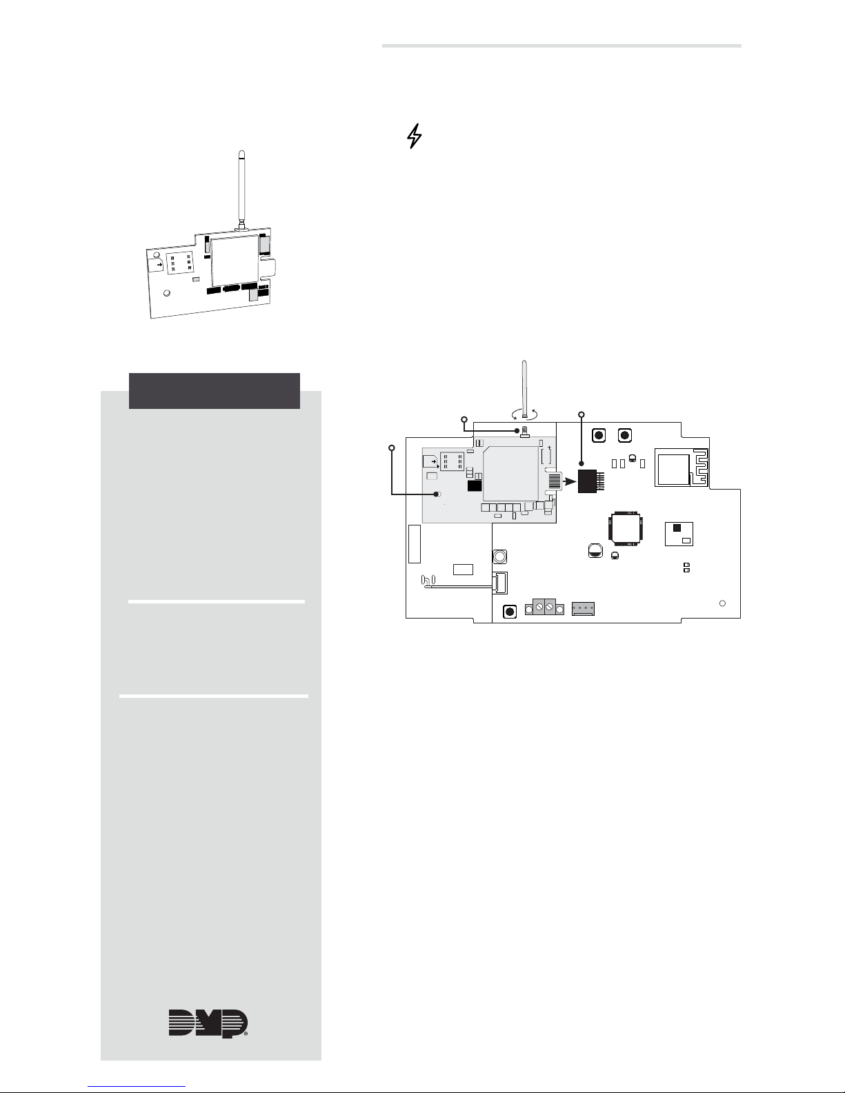
Figure 1: 265LTE-V PCB
1
INSTALL THE 265LTE-V
Caution: Touch grounded metal to discharge
static before handling the XTLplus.
1. Place the antenna onto the 265LTE-V SMA
connector and then twist the antenna until it
is securely tightened.
2. Slide the 265LTE-V into the XTLplus eightpin CELL MODULE connector, keeping the
265LTE-V parallel to the XTLplus.
3. Align the stando hole in the 265LTE-V with
the stando on the XTLplus, and then snap it
into place. See Figure 2.
The 265LTE-V Cellular
Communicator provides
a fully-supervised alarm
communication path over the
LTE network.
The 265LTE-V is installed on
the XTLplusTM and powered
by the panel so no additional
enclosure, power supply, or
battery back-up is needed.
Compatibility
All DMP XTLplus Series
panels.
Figure 2: Installing the 265LTE-V
on the XTLplus
What is Included
• 265LTE-V Cellular
Communicator
• External Antenna
RESETLOAD
BAT
PROG
R B
+ DC -
S
N
External
Antenna
SMA
Connector
Eight-Pin CELL MODULE
Connector
Stando
Hole
2
ACTIVATE THE 265LTE-V
Cellular service is required before using the
265LTE-V for signal transmission. The 265LTE-V
comes ready for activation with SecureComTM
Wireless. Use Remote LinkTM, the Dealer AdminTM
site (dealeradmin.securecomwireless.com),
the Tech APPTM, or call DMP Customer Service
(1-866-266-2826) to activate the 265LTE-V.
Remote Link Activation
1. Navigate to Remote Link and select a panel.
2. Select Program in the top menu and select
Communications from the drop-down
menu.
3. Select Cellular Network as the
Communication Type and click Activate.
4. Select SIM as the SIM Type.
5. Enter the SIM number found on the
265LTE-V label and click Activate.
6. Select a Rate Plan for the 265LTE-V and
click Activate.
265LTE-V CELLULAR
COMMUNICATOR
Installation Guide

265LTE-V Installation Guide | Digital Monitoring Products, Inc 2
1. Navigate to the Dealer Admin site (dealeradmin.securecomwireless.com).
2. Click Customers in the right-side menu and select a customer.
3. Click Add System.
4. Enter a System Name.
5. Select XTLplus from the System Type drop-down menu.
6. Select either Cellular or EASYconnect + Cell Backup in the Connection Type field.
7. Enter the SIM number found on the 265LTE-V label and click Get Status.
8. Enter the Account Number.
9. Select a Rate Plan for the 265LTE-V.
10. Click Activate Cellular Device.
3
TEST THE 265LTE-V
Dealer Admin Activation
1. Navigate to the Tech APP.
2. Tap Find a Customer then search for a customer.
3. Tap Add a System.
4. Enter a System Name.
5. Scan or enter the Serial #.
6. Select XTLplus from the System Type drop-down menu.
7. Select either Cellular or EASYconnect + Cell Backup in the Connection Type field.
8. Enter the Account Number.
9. Enter the SIM number found on the 265LTE-V label then tap Get SIM Status.
10. Select a Rate Plan for the 265LTE-V.
11. Tap Activate Cellular Device.
Tech APP Activation
The panel provides a diagnostic function to test the communication integrity and cellular
signal strength of the 265LTE-V to the nearest tower for the cellular carrier. To use the
diagnostic function, reset the panel, enter 2313 (DIAG), and press CMD.
Communication Status
This option tests the individual components of cellular or wireless network communication.
1. Select CELL STATUS from the diagnostic menu. Possible test results are shown in
Table 1.
2. Select YES to continue through the remaining component tests or select NO to
stop testing and return to CELL STATUS.
Cellular Strength
This option provides a way to test the cellular signal strength of the nearest tower for the
cellular carrier. Follow the steps below to test the cellular strength of the 265LTE-V:
1. Select CELL SIGNAL from the diagnostic menu then press a select key or area.
2. SIGNAL: displays. The numerical value of the cell signal strength is represented in
-dBm. The bars represent the signal strength of the 265LTE-V and range from 0-7.
Zero bars indicate a weak signal and seven bars indicate a strong signal.
Confirmed Faulty
MODEM OPERATING NO MODEM FOUND
IDENTIFIED NO SIM CARD
TOWER DETECTED NO TOWER
REGISTERED NOT REGISTERED
CONNECT SUCCESS
CONNECT ERROR
NOT ACTIVATED
CELL PATH GOOD NO ACK RECEIVED
Table 1: Communication Test Results
 Loading...