

Page 1
263EXT CELLULAR EXTENSION MODULES
Installation Guide
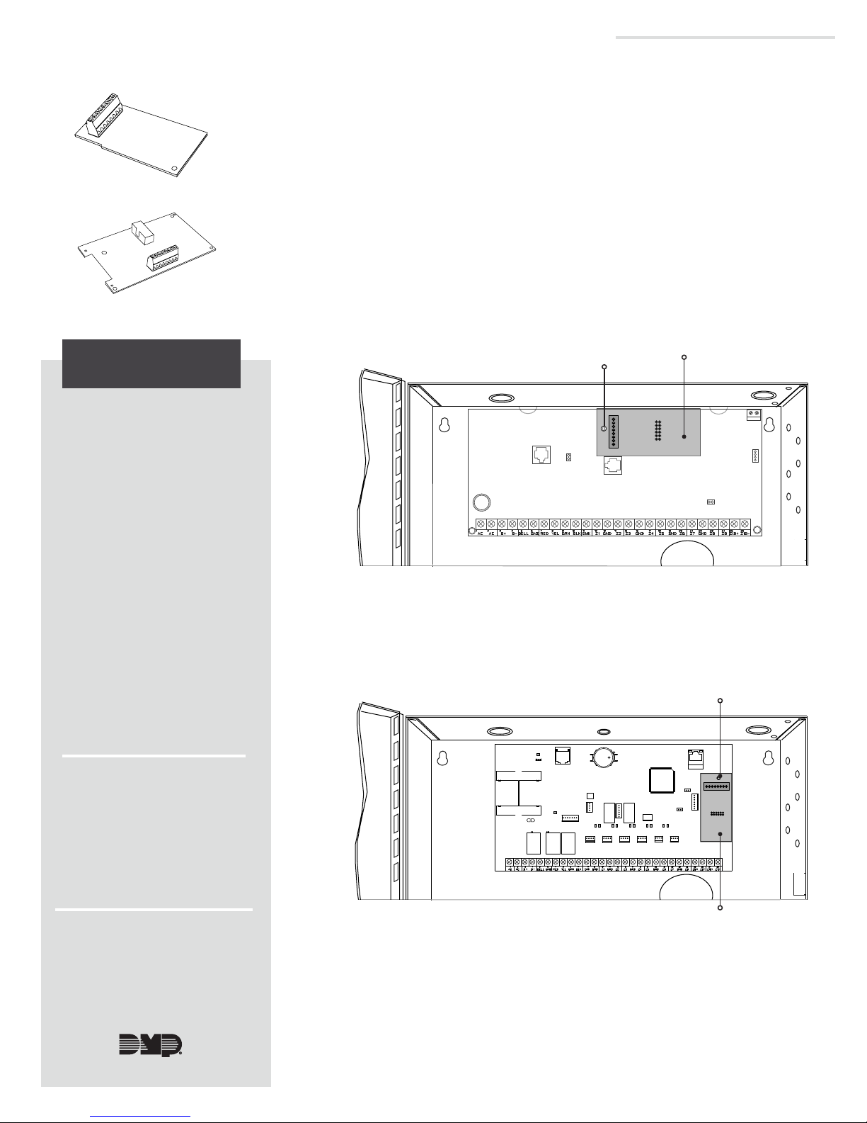
INSTALL THE PANEL MODULE
Caution: Touch grounded metal to discharge static before handling the
panel.
1
Figure 1: 263EXT Panel Module
Figure 2: 263EXT Remote Module
1. Open the panel enclosure and remove all power from the panel.
2. Insert the stando provided with the cell modem into the
XT30/XT50 or XR150/XR550 Series panel stando hole.
3. Align the 263EXT stando hole with the stando already placed
in the panel. Secure the 263EXT on the 12-pin cell module
header. See Figures 3 and 4.
4. Place the module on the panel.
DESCRIPTION
With the 263EXT Cellular
Extension Modules, you can now
maintain dB signal over
greater distances. The 263EXT
comes with two modules. The
panel module (see Figure 1) installs
directly on the panel inside the
enclosure while the remote module
(see Figure 2) installs with the cell
modem at the remote location that
provides the best signal.
The modules communicate with
each other through a wired
connection, maintaining dB
signal even from higher or lower
locations. Use CAT5 wire with
T568B Wiring to connect the
two modules. If using anything
other than CAT5 wire, it should
be 22AWG shielded wire with the
shield connected to the ground
terminal on both the panel side
module and the remote side
module. The 263EXT has a reach
of up to 300feet.
Stando and
Stando Hole
Back of the 263EXT
Figure 3: 263EXT Panel Module on an XT30/XT50 Panel
Stando and
Stando Hole
1
2
3
4
Compatibility
The 263EXT is compatible with
panels that have a 12-pin cell
module header, such as the
following panels:
• XT30/XT50 Series panels
• XR150/XR550 Series panels
What is Included
• 263EXT Panel Module
• 263EXT Remote Module
Back of the 263EXT
Figure 4: 263EXT Panel Module on an XR150/XR550 Panel
Page 2
Orange/White
2
3
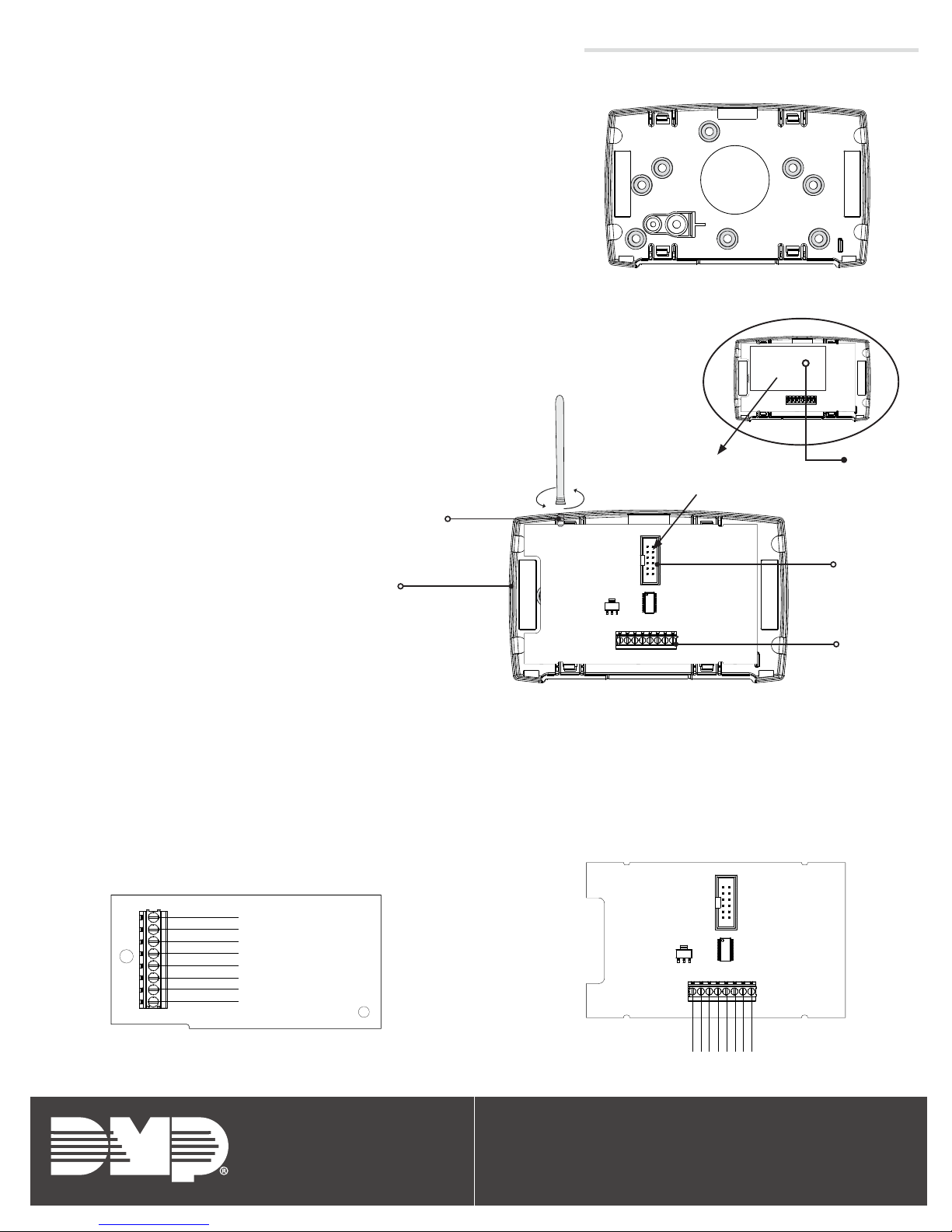
MOUNT THE REMOTE MODULE
Mount the remote module on a flat surface.
1. Remove the circuit board from the plastic housing by
loosening the clips on one side and gently lifting it out of
the housing base.
2. Use the included screws in the desired mounting hole
locations to attach the remote module to the surface.
See the shaded mounting hole locations in Figure 5.
3. Reinstall the circuit board in the housing base.
INSTALL THE REMOTE MODULE
1. Install the cellular communicator on the cell module
header.
2. Place the cellular antenna onto the SMA connector,
then twist the antenna until it is securely tightened
on to the remote module. See Figure6.
Figure 5: Mounting Hole Locations
Cellular
Antenna
Connect the cellular
communicator here
+12V
GND
4
1
5 6
2
3
Cellular
Communicator
4
SMA Connector
Cell Module
Plastic Housing
+12V
GND
4
1
5 6
2
3
Header
Terminal
Figure 6: Connecting the Cellular Antenna
CONNECT THE CABLE
You can use either a CAT5 cable or two shielded 22/4 cables for this installation. This guide uses a CAT5 cable. If
using shielded 22/4, you must connect the shield to the ground on each end.
The remote module can be installed up to 300feet away from the control panel.
1. Connect one end of the CAT5 cable to the terminal on the panel module. See Figure7.
Caution: Observe polarity and make sure wires are installed straight through.
2. Connect the other end of the CAT5 cable to the terminal on the remote module. See Figure8.
3. Apply power to the system to turn it back on.
Brown
Brown/White
5 6
Green
4
Blue/White
3
Blue
2
Green/White
1
Orange
GND
Orange/White
+12V
+12V
GND
1
Orange
4
5 6
2
3
Brown
Brown/White
Green
Blue/White
Blue
Green/White
Figure 7: CAT5 Cable on 263EXT Panel Module
Designed, engineered,
and manufactured in
263EXT INSTALLATION GUIDE | LT-1848 18402 | DIGITAL MONITORING PRODUCTS
Springfield, Missouri using U.S.
and global components.
LT-1848 1.01 18461
Figure 8: CAT5 Cable on 263EXT Remote Module
INTRUSION • FIRE • ACCESS • NETWORKS
2500 North Partnership Boulevard
Springfield, Missouri 65803-8877
888.436.7832 | DMP.com
 Loading...