

Page 1
1168 Wireless Smoke/CO/Low
Temp Detector
INSTALLATION AND PROGRAMMING GUIDE
Page 2

Page 3

TABLE OF CONTENTS
About the 1168 ............................... 1
Indicator LEDs................................................. 1
Power Supply .................................................. 1
Voice Annunciation ....................................... 1
Tamper Magnet ............................................... 1
Cadence Synchronization ......................... 1
Low Temp Sensor .......................................... 1
1168 Features ..................................2
Program the 1168 ...........................3
Select A Location ........................ 10
Install the 1168 .............................. 11
Mount the Base ...............................................11
Install the Battery ......................................... 12
Replace the Cover ....................................... 12
Mounting Guidelines ....................13
Authority Having Jurisdiction .................. 14
Locations to Avoid ....................................... 15
Commercial .................................................... 16
Multi-Family ....................................................16
Test the 1168 ..................................17
Smoke Test ...................................................... 17
CO Test.............................................................. 17
Additional Information ................21
Reset the Language Selection ................. 21
Supervision Message ................................... 21
Inspection Testing and Maintenance ..... 21
Replace The Batteries .................................22
NFPA 72 Guidelines .....................................23
Page 4

Compliance Specifications ........28
FCC Information ..........................30
Industry Canada Information ......31
Page 5

ABOUT THE 1168
The 1168 Wireless Smoke/CO/Low Temp Detector features multi-criteria smoke sensing
using a combination of photoelectric, heat, IR flame flicker, and carbon monoxide
indicators. The 1168 reports fire, CO, and low temp alarms to the control panel. Use the
onboard wireless transmitter to connect the 1168 with DMP1100Series Wireless Receivers.
INDICATOR LEDS
The 1168 has a multi-color top LED that
indicates the state of the device:
• GREEN—Supervisory indication; blinks
during power on, reset, and during
normal operation
• AMBER—Signal maintenance and
trouble events
• RED—Alarm (Smoke/CO/Low Temp)
Indicator lights on the side alarms (initiating
detector only):
• RED—Smoke
• BLUE—CO
POWER SUPPLY
The 1168 is powered by four 3.0V lithium
batteries. Battery life expectancy for the
unit is at least three years under normal
conditions.
1168 Wireless Smoke/CO/Low Temp Combo Detector Installation and Programming Guide 1
VOICE ANNUNCIATION
The 1168 audibly announces alarm and
maintenance requirements, enhancing
occupant understanding and evacuation.
TAMPER MAGNET
The 1168 features a tamper magnet which
sends a trouble message to the panel if the
detector is removed from the mounting
base.
CADENCE SYNCHRONIZATION
The 1168 provides cadence synchronization
with other 1168 or 1164 units on the system.
LOW TEMP SENSOR
The 1168 includes a low temperature
sensor that causes an alarm when inside
temperature falls below 41°F (5°C).
Page 6
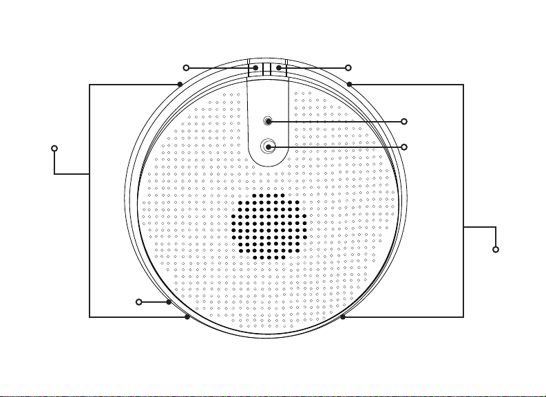
1168 FEATURES
CO Test Button Smoke Test Button
Indicator
Lights
1168 Wireless Smoke/CO/Low Temp Detector Installation and Programming Guide 2
CO Entry
Port
Figure 1: 1168 Features
Indicator
LED
IR Flame
Detector
Indicator
Lights
Page 7
PROGRAM THE 1168
When programming an 1168 Wireless Smoke/CO/Low Temp Detector, refer to the
appropriate panel programming guide as needed.
PROGRAMMER
ZONE INFORMATION
ZONE NO:
* UNUSED *
ZONE TYPE
FI PN EM SV
1168 Wireless Smoke/CO/Low Temp Combo Detector Installation and Programming Guide 3
PROGRAMMER MENU
Enter 6653 (PROG) at the keypad to enter the PROGRAMMER
menu.
ZONE INFORMATION
Press CMD until ZONE INFORMATION displays. Press a select
key or area to enter the menu.
ZONE NUMBER
Enter the zone number. Press CMD.
Note: The 1168 takes up to three zone numbers (Smoke,
CO, Temp). The zone numbers must be consecutive.
ZONE NAME
Denote the zone name as a fire zone. Press CMD.
ZONE TYPE
Press any select area. Press CMD to move to the next set of
menu options. Select FI (fire) as the ZONE TYPE.
Page 8
FIRE BEL OUT: 0
FIRE BELL OUT
Default is 0. Press CMD.
NEXT ZONE? NO YES
WIRELESS? YES
TRANSMITTER
SERIAL #: -
CONTACT: FIRE
1168 Wireless Smoke/CO/Low Temp Detector Installation and Programming Guide 4
NEXT ZONE
At the NEXT ZONE? prompt, select NO.
WIRELESS
At the WIRELESS? prompt, select YES.
Note: If you are programming the 1168 onto a zone that
can be either hardwired or wireless, then this prompt
appears. If the zone you are programming is wireless-only,
then the prompt does not appear.
SERIAL NUMBER
Enter the eight-digit SERIAL #: - found on the device and press
CMD.
CONTACT TYPE
Enter the CONTACT type as FIRE and press CMD.
Page 9

SUPVSN TIME: 240
SUPERVISION TIME
Enter the SUPVSN TIME, and press CMD.
NEXT ZN? YES
ZONE NO:
* UNUSED *
ZONE TYPE
CO IN
FIRE BEL OUT: 0
1168 Wireless Smoke/CO/Low Temp Combo Detector Installation and Programming Guide 5
NEXT ZONE
At the NEXT ZONE? prompt, select YES.
ZONE NUMBER
Enter the zone number. This number must be consecutive
with the previous zone. For example, if 500 was entered for
Fire,501 should be entered here. Press CMD.
ZONE NAME
Denote the zone name as a carbon monoxide (CO) zone. Press
CMD.
ZONE TYPE
Press any select area. Press CMD three times to move to the
last set of menu options. Select CO (carbon monoxide) as the
ZONE TYPE.
FIRE BELL OUT
Default is 0. Press CMD.
Page 10
NEXT ZONE? NO YES
NEXT ZONE
At the NEXT ZONE? prompt, select NO.
WIRELESS? YES
TRANSMITTER
SERIAL #: -
CONTACT: CO
SUPVSN TIME: 240
1168 Wireless Smoke/CO/Low Temp Detector Installation and Programming Guide 6
WIRELESS
At the WIRELESS? prompt, select YES.
Note: If you are programming the 1168 onto a zone that
can be either hardwired or wireless, then this prompt
appears. If the zone you are programming is wireless-only,
then the prompt does not appear.
SERIAL NUMBER
Enter the eight-digit SERIAL #: - found on the device and press
CMD.
CONTACT TYPE
Enter the CONTACT type as CO and press CMD.
SUPERVISION TIME
Enter the SUPVSN TIME, and press CMD.
Page 11

NEXT ZN? YES
NEXT ZONE
At the NEXT ZONE?, prompt, select YES.
ZONE NO:
ZONE NAME:
ZONE TYPE
FI PN EM SV
FIRE BEL OUT: 0
NEXT ZONE? NO YES
1168 Wireless Smoke/CO/Low Temp Combo Detector Installation and Programming Guide 7
ZONE NUMBER
Enter the zone number. This number must be consecutive with
the previous zones. For example, if 51 was entered for Fire and
52 was entered for CO, 53 should be entered here. Press CMD.
ZONE NAME
Denote the zone name as a temperature (TEMP) zone. Press
CMD.
ZONE TYPE
Press any select area. Press CMD to move to the next set of
menu options. Select SV as the ZONE TYPE.
FIRE BELL OUT
Default is 0. Press CMD.
NEXT ZONE
At the NEXT ZONE? prompt, select NO.
Page 12

WIRELESS? YES
WIRELESS
At the WIRELESS? prompt, select YES.
Note: If you are programming the 1168 onto a zone that
can be either hardwired or wireless, then this prompt
appears. If the zone you are programming is wireless-only,
then the prompt does not appear.
TRANSMITTER
SERIAL #: -
CONTACT: TEMP
SUPVSN TIME: 240
NEXT ZN? NO
1168 Wireless Smoke/CO/Low Temp Detector Installation and Programming Guide 8
SERIAL NUMBER
Enter the eight-digit SERIAL #: - found on the device and press
CMD.
CONTACT TYPE
Enter the CONTACT type as TEMP and press CMD.
SUPERVISION TIME
Enter the SUPVSN TIME, and press CMD.
NEXT ZONE
At the NEXT ZONE?, prompt, select NO.
Page 13

BELL OPTIONS
BELL OPTIONS
Press CMD until BELL OPTIONS displays, and then press a
select key or area.
FIRE BELL ACTION...
FIRE TYPE: T
1168 Wireless Smoke/CO/Low Temp Combo Detector Installation and Programming Guide 9
FIRE BELL ACTION
At FIRE BELL ACTION FIRE TYPE:, select T (temporal) as the
action type.
Note: Program this option to enable cadence
synchronization with other 1168 and 1164 units on the
system.
Page 14

SELECT A LOCATION
Use the LED survey operation to select a proper location for the 1168. The LED survey
operation allows one person to confirm communication with the wireless receiver or panel
while the cover is removed. Because the transmitter LED on the 1168 is not visible, use a
separate 1100 Series transmitter for the LED survey operation, such as the 1106 Universal
Transmitter.
1. Hold the 1106 in the exact desired location.
2. Press the tamper switch on the 1106 to send data to the panel and determine if
communication is confirmed or faulty.
Confirmed: If communication is confirmed, for each press or release of the
tamper switch the LED blinks immediately on and immediately o.
Faulty: If communication is faulty, the LED remains on for up to eight
seconds or flashes multiple times in a quick succession. Relocate the wireless
receiver until the LED confirms clear communication.
1168 Wireless Smoke/CO/Low Temp Detector Installation and Programming Guide 10
Page 15

INSTALL THE 1168
MOUNT THE BASE
1
After selecting a location, mount the 1168 on a flat wall or ceiling. The ensure optimum
performance, mount the 1168 away from large metal objects. See Mounting Guidelines
for more information.
1. Grasp the detector and twist counterclockwise to remove the detector from
the mounting base. See Figure 2.
2. Use the supplied screws and anchors to mount the base to the surface. See
Figure3.
Mounting Hole
Mounting Hole
Figure 2: Remove
Detector from Base
1168 Wireless Smoke/CO/Low Temp Combo Detector Installation and Programming Guide 11
Figure 3: Mounting
Hole Locations
Page 16

INSTALL THE BATTERY
2
The 1168 comes pre-installed with four 3.0V
lithium batteries. Firmly grasp the battery pull-tab
on the battery compartment and remove it. See
Figure4.
REPLACE THE COVER
After installing the battery, replace the cover back
3
on the base. Follow the directions below:
1. Place the detector on the base, aligning
the raised tab on the detector’s lip and the
cover latch on the base’s lip.
2. Rotate the detector until it clicks into
place.
1168 Wireless Smoke/CO/Low Temp Detector Installation and Programming Guide 12
Figure 4: Battery Location
Page 17

MOUNTING GUIDELINES
In addition to NFPA 72, use the following location guidelines to optimize performance and
reduce false alarms. Refer to Figure5.
• Place ceiling-mounted smoke detectors in the center of a room or hallway at
least4inches from walls and partitions. If a ceiling is sloped, peaked, or gabled,
place the detector 3 feet from the highest-point. If mounting to suspended ceiling
tile, the tile must be secured with an appropriate fastener across ceiling panel
supports.
• Place wall-mounted smoke detectors at least 4 inches below the ceiling.
• Mount smoke detectors on a firm, permanent surface.
• Place in environmentally-controlled areas with a temperature
range between41°Fand 100°F (5°C and 37.8°C) and humidity
between0%and90%non-condensing.
1168 Wireless Smoke/CO/Low Temp Combo Detector Installation and Programming Guide 13
Page 18

AUTHORITY HAVING JURISDICTION
A proper location is critical to ensuring proper operation. Equipment should be installed
in accordance with the National Fire Protection Association’s (NFPA) Standard 72,
Chapters2 and 8. You may need to reference other chapters of NFPA 72 or NFPA 101.
Smoke detector regulations vary from state to state, so contact the Authority Having
Jurisdiction (AHJ). Where public safety is primary, the AHJ may be a federal, state, local,
or other regional department or individual (such as a fire chief, fire marshal, chief of a fire
prevention bureau, labor or health department, building ocial, electrical inspector, or
others having statutory authority.
For insurance purposes, an AHJ may be an insurance inspection department, rating
bureau, or other insurance company representative. Sometimes, a property owner or
their designated agent assumes the role of the AHJ. At government installations, the
commanding ocer or department ocial may be the AHJ.
1168 Wireless Smoke/CO/Low Temp Detector Installation and Programming Guide 14
Page 19

LOCATIONS TO AVOID
Smoke detectors should not be installed in or near the following locations:
• In or near areas where combustion particles are common (kitchens, garages,
furnaces, hot water heaters, or gas space heaters).
• On ceilings in rooms next to kitchens if there is no transom between the room and
the kitchen.
• In damp or humid areas, such as bathrooms with showers.
• In extremely cold or hot areas.
• In dusty, dirty, or insect-infested areas.
• Near air conditioners, heating registers, or any other ventilation source that may
interfere with smoke entering the detector.
• Near fresh air inlets or returns or excessively drafty areas (heating or air
conditioning vents, fans, etc.).
• In dead-air spaces at the top of peaked ceilings or corners where walls and ceiling
meet.
• Near fluorescent light fixtures (smoke detectors should be at least 10 feet away).
1168 Wireless Smoke/CO/Low Temp Combo Detector Installation and Programming Guide 15
Page 20

Stairwell
Oce
Oce
Hall
Hall
Lobby
Oce
Oce
Stairwell
Men’s
Conference
Room
Hall
Closet
Women’s
Oce
OceOce
In commercial buildings,
place smoke detectors in
stairwells and every room on
each level.
COMMERCIAL
Stairwell
Third Floor
Second Floor
First Floor
1168 Wireless Smoke/CO/Low Temp Detector Installation and Programming Guide 16
Kitchen
Bathroom
ApartmentApartment
Stairwell
Apartment Apartment Apartment
Living
Room
Dining
Hall
Figure 5: Smoke Detector Placement Locations
Bedroom
Apartment
MULTI-FAMILY
In multifamily buildings,
place smoke detectors in
hallways and stairwells on
each level.
Inside each apartment,
place smoke detectors in
the living area, hallway, and
each bedroom.
Page 21

TEST THE 1168
Note: If particulate like canned smoke is the only input to the detector, an alarm will
only occur after five minutes of alarm-level particulate exposure.
SMOKE TEST
For more information, refer to the LED Indication and Sounder table.
1. Press the Smoke Test button on the 1168 to initiate a smoke alarm test. The fire
alarm will not sound at the panel.
2. To initiate a functional smoke test, press and hold the Smoke Test button
for5seconds.
3. Hold a container of canned smoke close to the smoke entry openings. Spray the
smoke directly into the detector for 1 second or until the unit goes into alarm. The
fire alarm sounds at the panel.
CO TEST
For more information, refer to the LED Indication and Sounder table.
1. Press the CO Test button on the 1168 to initiate the CO test. The CO alarm will not
sound at the panel.
2. To initiate a functional CO test, press and hold the CO Test button for 5 seconds.
3. Hold a container of Solo C6 CO Detector Tester (or similar) close to the CO Gas
Entry Port. See Figure 1 for port location. Spray the can directly into the detector
for 1second or until the unit goes into alarm. The CO alarm sounds at the panel.
1168 Wireless Smoke/CO/Low Temp Combo Detector Installation and Programming Guide 17
Page 22

LED Indication and Sounder
Mode Status LED
(Top)
Smoke Alarm
Smoke System
(functional)
CO Test
1;2
Blink RED once
every sec
Blink RED once
every 10 secs
1;2
Blink GREEN
once a sec
Side LED
Sounder Speaker
Windows
Dark Temp-3 Voice smoke sensor
test result and
remaining battery life
Blink RED
once every 10
Temp-3 No voice
announcement
secs
Dark Temp-4 Voice CO sensor test
result, remaining
sensor life, and
remaining battery life
CO Test—
Successful gas
Blink RED
every 10 secs
entry
Low Battery Blink AMBER
every 10 secs
1168 Wireless Smoke/CO/Low Temp Detector Installation and Programming Guide 18
Blink BLUE
Temp-4 “Warning: Carbon
every 10 secs
Dark Chirp
every 45
secs after
7 days
Monoxide. Move to
fresh air.”
Voice instructions
when chirp is hushed
by pressing either test
button
Page 23

LED Indication and Sounder
Mode Status LED
(Top)
Smoke
Maintenance
CO Trouble Double Blink
CO End of
Life3—First 29
days
CO End of
Life3—First 30
days
Freeze Warning:
Temp lower than
41°F (5°C)
Blink AMBER
every 5 secs
AMBER every
5 secs
Double Blink
AMBER every
3 secs
Double Blink
AMBER every
3 secs
Blink RED
every 10 secs
1168 Wireless Smoke/CO/Low Temp Combo Detector Installation and Programming Guide 19
Side LED
Sounder Speaker
Windows
Dark Silent Voice smoke
maintenance
instructions if either
test button is pressed
Dark Silent No voice
announcement
Dark Silent Voice end of life
instructions when
either test button is
pressed
Dark Chirp
every 45
secs
Voice end of life
instructions when
either test button is
pressed
Dark Silent No voice
announcement
Page 24

1
Test activated by the test switch or from the controller. Detector is functioning properly
(within proper sensitivity).
2
If Test mode is activated and the LED and Sounder do not function, check for
maintenance or trouble conditions.
3
Starts chirping after 30 days, continues until the batteries are replaced or die.
1168 Wireless Smoke/CO/Low Temp Detector Installation and Programming Guide 20
Page 25

ADDITIONAL INFORMATION
RESET THE LANGUAGE SELECTION
Press and hold both the Smoke and CO test switch simultaneously for 10seconds, then
release. The green light will flash rapidly. Press and hold both buttons again for one second
and release. The sensor begins speaking a welcome message. Language selection can now
be made. The options are English and Spanish.
SUPERVISION MESSAGE
When a wireless receiver is installed, a receiver is restarted, the panel is reset, or if
programming is complete, then the supervision time is reset. If the receiver has been
powered down for more than one hour, then the 1168 may take up to an additional hour
to send a supervision message. A missing message may display on the keypad until the
supervision message is sent.
INSPECTION TESTING AND MAINTENANCE
The 1168 is designed for easy field service and maintenance. When installed and used
properly, the 1168 requires minimal maintenance. The device should be functionally tested
per NFPA 72 for system type smoke detectors. When a smoke detector requires
maintenance, the red LED blinks every 5 seconds.
Caution: Smoke alarms cannot provide warnings for fires resulting from explosions,
smoking in bed or other furniture, ignition of flammable liquids, vapors and gases,
children playing with matches or lighters. Smoke detectors are not to be used with
detector guards unless the combination has been evaluated and found suitable for
that purpose.
1168 Wireless Smoke/CO/Low Temp Combo Detector Installation and Programming Guide 21
Page 26

REPLACE THE BATTERIES
Caution: The batteries used in this device may present a fire or chemical burn hazard if
mistreated. Do not recharge, disassemble, heat above 212°F (100°C) or dispose of in
fire. Use only Panasonic CR123A Lithium batteries. Use of other batteries may present
a risk of fire or explosion. Keep used batteries away from children. Dispose of used
batteries properly.
Remove old batteries. Wait 10 seconds and then replace with four new batteries. To
avoid a low battery indication when installing new batteries, all four batteries must be
installed within 15seconds of installing the first one. Any low battery condition that
may have occurred should clear when the backplate is installed.
1168 Wireless Smoke/CO/Low Temp Detector Installation and Programming Guide 22
Page 27

NFPA 72 GUIDELINES
Total (Complete) Coverage
If required, total coverage shall include all rooms, halls, storage areas, basements, attics,
lofts, spaces above suspended ceilings, and other subdivisions and accessible spaces; and
the inside of all closets, elevator shafts, enclosed stairways, dumbwaiter shafts, and chutes.
Inaccessible areas shall not be required to be protected by detectors. (For exceptions,
refer to NFPA 72.)
Partial Coverage
If required, partial detection systems shall be provided in all common areas and work
spaces, such as corridors, lobbies, storage rooms, equipment rooms, and other tenant-less
spaces in those environments suitable for proper detector operation in accordance with
this code.
Selective Coverage
Where codes, standards, laws, or authorities having jurisdiction require the protection of
selected areas only, the specified areas shall be protected in accordance with this code.
Supplementary (Non required) Coverage
Where installed, detection that is not required by an applicable law, code, or standard,
whether total (complete), partial, or selective coverage, shall conform to the requirements
of this code. (For exceptions, refer to NFPA 72 Spacing Requirements.) Where non
required detection devices are installed for a specific hazard, additional non required
detection devices shall not be required to be installed throughout an entire room or
building.
1168 Wireless Smoke/CO/Low Temp Combo Detector Installation and Programming Guide 23
Page 28

Heat-Sensing Fire Detectors
Heat-sensing fire detectors shall be installed in all areas where required by the NFPA
codes and standards or by the authority having jurisdiction.
Detection in New Apartment Buildings
Approved, single-station smoke alarms shall be installed in accordance with 7-6.2.10 of
NFPA 101 outside every sleeping area in the immediate vicinity of the bedrooms and on
all levels of the dwelling unit including basements. (For exceptions, refer to this section of
NFPA 72.)
Detection in Existing Apartment Buildings
Approved, single-station smoke alarms shall be installed in accordance with 7-6.2.10 of
NFPA 101 outside every sleeping area in the immediate vicinity of the bedrooms and on
all levels of the dwelling unit including basements. (For exceptions, refer to this section of
NFPA 72.)
1168 Wireless Smoke/CO/Low Temp Detector Installation and Programming Guide 24
Page 29

WARNING! Limitation of Smoke Detectors
Wireless smoke alarms are very reliable, but may not work under all conditions. No fire
alarm provides total protection of life or property. Smoke alarms are not a substitute for
life insurance.
Smoke alarms require a source of power to work. This smoke alarm will not operate and
the alarm will not sound if the battery is dead or not installed properly.
Smoke alarms may not be heard. A sound sleeper or someone who has taken drugs or
alcohol may not awaken if the alarm is installed outside a bedroom. Closed or partially
closed doors and distance can block sound. This alarm is not designed for the hearing
impaired.
Smoke alarms may not always activate and provide warning early enough. Smoke alarms
only activate when enough smoke reaches the alarm. If a fire starts in a chimney, wall, roof,
on the other side of closed doors, or on a dierent level of the property, enough smoke
may not reach the alarm for it to alarm.
Smoke alarms are a significant help in reducing loss, injury, and even death. However, no
matter how good a detection device is, nothing works perfectly under every circumstance
and we must warn you that you cannot expect a smoke alarm to ensure that you will never
suer any damage or injury.
1168 Wireless Smoke/CO/Low Temp Combo Detector Installation and Programming Guide 25
Page 30

Fire Prevention and Escape
The purpose of an early warning smoke alarm is to detect the presence of fire in its early
stages and sound an alarm, giving the occupants time to exit the premises safely.
Avoid Fire Hazards
• Do not smoke in bed.
• Do not leave children home alone.
• Never clean with flammable liquids such as gasoline.
• Properly store materials.
• Use general good housekeeping techniques to keep your home neat and tidy. A
cluttered basement, attic, or other storage area is an open invitation to fire.
• Use combustible materials and electrical appliances carefully and only for their
intended uses.
• Do not overload electrical outlets.
• Do not store explosive and/or fast burning materials in your home.
• Even after proper precautions have been taken, fires can start. Be prepared.
1168 Wireless Smoke/CO/Low Temp Detector Installation and Programming Guide 26
Page 31

Operation Modes
Mode Status LED
(Top)
Power Up Blink GREEN
every 2 secs
Normal
(Standby)
Smoke Alarm Blink RED
Single blink
GREEN every
10 secs
every 10 secs
Side LED
Sounder Speaker
Windows
Dark Silent Voice welcome,
instructions after first
time power-up or after
default
Dark Silent No voice
announcement
Blink RED Temp-3 Voice smoke warning
CO Alarm Blink RED
Blink BLUE Temp-4 Voice CO warning
every 10 secs
Powered Down Dark Dark Silent No voice
announcement
1168 Wireless Smoke/CO/Low Temp Combo Detector Installation and Programming Guide 27
Page 32

COMPLIANCE SPECIFICATIONS
Specifications
Battery Life Expectancy ETL Rating: 1 Year
Under Normal Conditions: 3 Years
Battery Type 4 x 3.0 V, CR123A Lithium; Panasonic CR123A only
Sensitivity UL Limits 0.9 to3.50%/ft; ULC Limits 0.9 to 3.08%/ft
Audible Signal 85dBA
Frequency Range 905-924 MHz
Dimensions 16.002cm Diameter x 4.19cm Thick
6.3in Diameter x 1.65in Thick
Tamper Cover
Operating Temperature 32°F to 100°F; 0°C to 38°C
Storage Temperature 14°F to 158°F; -10°C to 70°C
Relative Humidity 20% to 95% RH (Agency Compliance is 93% max),
Non-condensing
Color White
1168 Wireless Smoke/CO/Low Temp Detector Installation and Programming Guide 28
Page 33

Patents
U.S. Patent No. 7,239,236
Compatibility
1100D Series Wireless Receiver with firmware version 203 or higher
1100X Series Wireless Receiver with firmware version 203 or higher
XT30/XT50 Series Panels with firmware version 1.92 or higher
XR150/XR550 Series Panels with firmware version 1.92 or higher
XTLplus Series Panels with firmware version 1.92 or higher
XTLtouch Series Panels with firmware version 1.92 or higher
Certifications
FCC Part 15 Registration ID CCKPC0204
IC Registration ID 5251A-PC0204
Intertek (ETL) Listed
ANSI/UL 268 Smoke-Automatic Fire Detectors
ANSI/UL 2075 Gas and Vapor Detectors and Sensors
1168 Wireless Smoke/CO/Low Temp Combo Detector Installation and Programming Guide 29
Page 34

FCC INFORMATION
This device complies with Part 15 of the FCC Rules. Operation is subject to the following two conditions:
1. This device may not cause harmful interference, and
2. This device must accept any interference received, including interference that may cause
undesired operation.
The antenna used for this transmitter must be installed to provide a separation distance of at least
20cm (7.874 in.) from all persons. It must not be located or operated in conjunction with any other
antenna or transmitter.
Changes or modifications made by the user and not expressly approved by the party responsible for
compliance could void the user’s authority to operate the equipment.
Note: This equipment has been tested and found to comply with the limits for a Class B digital
device, pursuant to part 15 of the FCC Rules. These limits are designed to provide reasonable
protection against harmful interference in a residential installation. This equipment generates,
uses and can radiate radio frequency energy and, if not installed and used in accordance with the
instructions, may cause harmful interference to radio communications. However, there is no
guarantee that interference will not occur in a particular installation. If this equipment does cause
harmful interference to radio or television reception, which can be determined by turning the
equipment o and on, the user is encouraged to try to correct the interference by one or more of
the following measures:
1. Reorient or relocate the receiving antenna.
2. Increase the separation between the equipment and receiver.
3. Connect the equipment into an outlet on a circuit dierent from that to which the
receiver is connected.
4. Consult the dealer or an experienced radio/TV technician for help.
1168 Wireless Smoke/CO/Low Temp Detector Installation and Programming Guide 30
Page 35

INDUSTRY CANADA INFORMATION
This device complies with Industry Canada License-exempt RSS standard(s). Operation is subject to the
following two conditions:
1. This device may not cause interference, and
2. This device must accept any interference, including interference that may cause undesired
operation of the device.
This system has been evaluated for RF Exposure per RSS-102 and is in compliance with the limits
specified by Health Canada Safety Code 6. The system must be installed at a minimum separation
distance from the antenna to a general bystander of 7.87 inches (20 cm) to maintain compliance with
the General Population limits.
Le présent appareil est conforme aux CNR d’Industrie Canada applicables aux appareils radio exempts
de licence. L’exploitation est autorisée aux deux conditions suivantes:
1. l’appareil ne doit pas produire de brouillage, et
2. l’utilisateur de l’appareil doit accepter tout brouillage radioélectrique subi, même si le
brouillage est susceptible d’en compromettre le fonctionnement.
L’exposition aux radiofréquences de ce système a été évaluée selon la norme RSS-102 et est jugée
conforme aux limites établies par le Code de sécurité 6 de Santé Canada. Le système doit être installé
à une distance minimale de 7.87 pouces (20 cm) séparant l’antenne d’une personne présente en
conformité avec les limites permises d’exposition du grand public.
Information furnished is believed to be accurate and reliable.
This information is subject to change without notice.
1168 Wireless Smoke/CO/Low Temp Combo Detector Installation and Programming Guide 31
Page 36

LT-1898 19354 1.01 © 2019 Digital Monitoring Products, Inc.
 Loading...