

Page 1
INSTALLATION AND PROGRAMMING GUIDE
1134 Wireless
Wiegand Module
Page 2

Page 3

About the 1134 ............................................ 1
Power Supply ......................................................... 1
Zone Terminals ...................................................... 1
Annunciators .......................................................... 1
LED Indicators ....................................................... 1
LED Survey ............................................................ 2
Form C Relay ......................................................... 2
Programming Connection ................................ 2
Dry/Wet Contact ................................................. 2
PCB Features ...............................................3
Program the 1134 ........................................4
Part 1: Device Setup ............................................ 4
Part 2: Zone Information .................................. 5
Install the 1134 ............................................6
Mount the 1134 ...................................................... 6
Wire the Electronic Lock .................................. 7
Isolation Relay ...................................................... 9
Install the 333 Suppressor ..............................10
Wire the Zone Terminals ...................................11
Connect a Card Reader ....................................13
TABLE OF CONTENTS
Program the 1134 Options ....................... 15
Program Start Display ......................................15
Serial Number Display ...................................... 15
Initialization Option ........................................... 15
Initialize Confirm Option .................................16
Activate Zone 2 Bypass ...................................16
Zone 2 Bypass Time .......................................... 17
Relock on Zone 2 Change ............................... 17
Activate Zone 3 Request to Exit ..................18
Zone 3 REX Strike Time ...................................19
Activate Onboard Speaker .............................19
Custom Card Definitions ........................ 20
Any Card Format ...............................................20
Card Formats ......................................................20
Format Name ......................................................20
Wiegand Code Length ..................................... 21
Site Code Position and Length ....................22
User Code Position and Length ................... 22
Require Site Code .............................................22
Site Code Display ..............................................23
Number of User Code Digits ......................... 23
Page 4

No Communication with Panel ....................24
Remove Keypad .................................................25
Public Card Formats ............................... 26
Product Specifications ............................27
Readers and Credentials .........................28
FCC Information ...................................... 30
Industry Canada Information .................. 31
Page 5

Digital Monitoring Products, Inc. | 1134 Installation and Programming Guide 1
ANNUNCIATORS
An on-board programmable piezo provides local
annunciation at the 1134. You can also connect a
variety of switched ground annunciators to the
1134 for remote annunciation.
LED INDICATORS
The 1134 provides two indicator LEDs. The
SURVEY (Red) LED turns on for the same
duration as the door strike relay. The WIEGAND
(Yellow) LED turns on for one second to indicate
receipt of a valid Wiegand input.
The 1134 Wireless Wiegand Module allows you to use the powerful built-in access control capability of
DMP panels. DMP panels provide access control, arming, and disarming using proximity, mag-stripe,
biometric or other Wiegand-output authentication devices.
The 1134 connects and operates wirelessly with DMP panels. A keypad may be plugged directly into
the 1134 for local programming. The 1134 includes the following features:
POWER SUPPLY
The 1134 operates at 12/24VDC from the power
supply supporting a door’s magnetic lock or
door-strikes. It also provides a 10 Amp Form C
relay contact for lock control.
ZONE TERMINALS
The 1134 has four onboard zones that can be
programmed for a variety of burglary or access
control applications.
ABOUT THE 1134
Page 6

2 1134 Installation and Programming Guide | Digital Monitoring Products, Inc.
LED SURVEY
The 1134 provides a Survey LED capability to
allow one person to confirm communication with
the wireless receiver while the cover is removed.
Mount the 1134 away from large metal objects
because it may impair performance. Do not
mount the 1134 inside a metal enclosure or install
in a drop ceiling.
1. With the cover removed, hold the 1134 in the
exact desired location.
2. Press the tamper switch to send data to the
panel and determine if communication is
confirmed or faulty.
Confirmed: If communication is
confirmed, for each press or release of the
tamper switch, the LED blinks
immediately on and immediately o.
Faulty: If communication is faulty, the
LED remains on for about 8seconds or
flashes multiple times in quick succession.
Relocate the 1134 or receiver until the LED
confirms clear communication.
FORM C RELAY
The 1134’s Form C relay draws up to 35mA of
current. Refer to the NC/C/NO (Dry Contact
Relay) and the Isolation Relay sections in this
document for more information.
PROGRAMMING CONNECTION
The 1134 provides a keypad programming
connection that allows you to use a standard
DMP LCD keypad for initial setup.
DRY/WET CONTACT
Apply power to the door relay (WET setting) or
leave it unpowered (DRY setting).
Page 7

Digital Monitoring Products, Inc. | 1134 Installation and Programming Guide 3
1
2
3
4 5 6 7
8
10
11 12 13 14
9
LC ASRED WHT GRN BLK Z1 Z2 Z3 Z4RA GND GND
NC
C
NO
SURVEY
WIEGAND
PROG
DRY
WET
RESET
TAMPER
DISABLE
SURVEY
GND
LED Survey
Button
Piezo
Wiegand
Inputs
Status
Indicator
Outputs
Zones
Reset
Tamper
LED
Indicators
Keypad
Programming
Header
Power
Supply
Door Relay
Terminal
Dry/Wet
Contact
PCB FEATURES
Figure 1: PCB Features
Page 8

4 1134 Installation and Programming Guide | Digital Monitoring Products, Inc.
PROGRAM THE 1134
Refer to the panel programming guide as needed.
1. Reset the panel.
2. At the keypad, enter 6653 (PROG) to access the PROGRAMMER menu.
PART 1: DEVICE SETUP
1. In DEVICE SETUP, press CMD until you get to DEVICE NO: -.
2. Enter a DEVICE NO:- and press CMD.
3. Enter a DEVICE NAME and press CMD.
4. (XT30/XT50 only) Select YES when WIRELESS? displays.
5. (XR150/XR550 only) Select DOOR for DEVICE TYPE and press CMD.
6. (XR150/XR550 only) Select WLS at COMM TYPE and press CMD.
Note: Panel version 191 or higher software is required.
7. Enter the eight-digit SERIAL#:- and press CMD.
Note: Enter the Type 14 serial number found on the 1134 PCB or by connecting a keypad to the
header on the 1134.
8. Enter the SUPRVSN TIME and press CMD.
Page 9

Digital Monitoring Products, Inc. | 1134 Installation and Programming Guide 5
PART 2: ZONE INFORMATION
1. In ZONE INFORMATION, enter the wireless ZONE NO: - and press CMD.
2. Enter the ZONE NAME and press CMD.
3. Select the ZONE TYPE and press CMD.
4. At NEXT ZN?, select NO.
5. Select YES when WIRELESS? displays.
6. Enter the eight-digit SERIAL#:- and press CMD.
Note: Enter the Type 08 serial number found on the 1134 PCB or by connecting a keypad to the
header on the 1134.
7. Enter the CONTACT number being used.
8. Enter the SUPRVSN TIME and press CMD.
9. At the NEXT ZN? prompt, select YES and continue to program up to three more zones.
Note: Zones must be entered sequentially. For example, if you program zone 71, you need to
program zone 72 as the next contact. Use the same serial number for each contact.
Page 10
6 1134 Installation and Programming Guide | Digital Monitoring Products, Inc.
INSTALL THE 1134
The 1134 comes in a high-impact plastic housing that you can mount directly to a wall, backboard,
or other flat surface.
For easy installation, the back and ends of the 1134 housing have wire entrances. The back also
contains multiple mounting holes that allow you to mount the 1134 on a single-gang switch box.
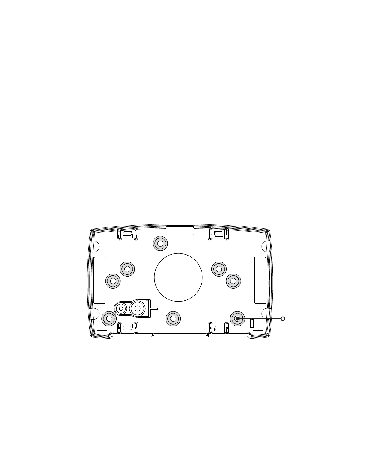
DMP recommends mounting the 1134 near the protected door. Remove the PCB from the housing
base to install the housing to the wall. See Figure2 for mounting hole locations.
1
MOUNT THE 1134
Mounting Hole
Figure 2: Mounting Hole Locations
Page 11
Digital Monitoring Products, Inc. | 1134 Installation and Programming Guide 7
234 5 6 7
8
10
11 12 13 14
9
LC AS
GRN BLK Z1 Z2 Z3 Z4RA GND GND
NC
C
NO
Model 333
Suppressor
–+
DC Door Strike
12/24 VDC
Power Supply
Normally Open
GND
The 1134 provides a Form C (SPDT) relay for controlling locks and other electronically-controlled
barriers. The three relay terminals marked NO C NC allow you to connect the device wiring to
the relay for module control.
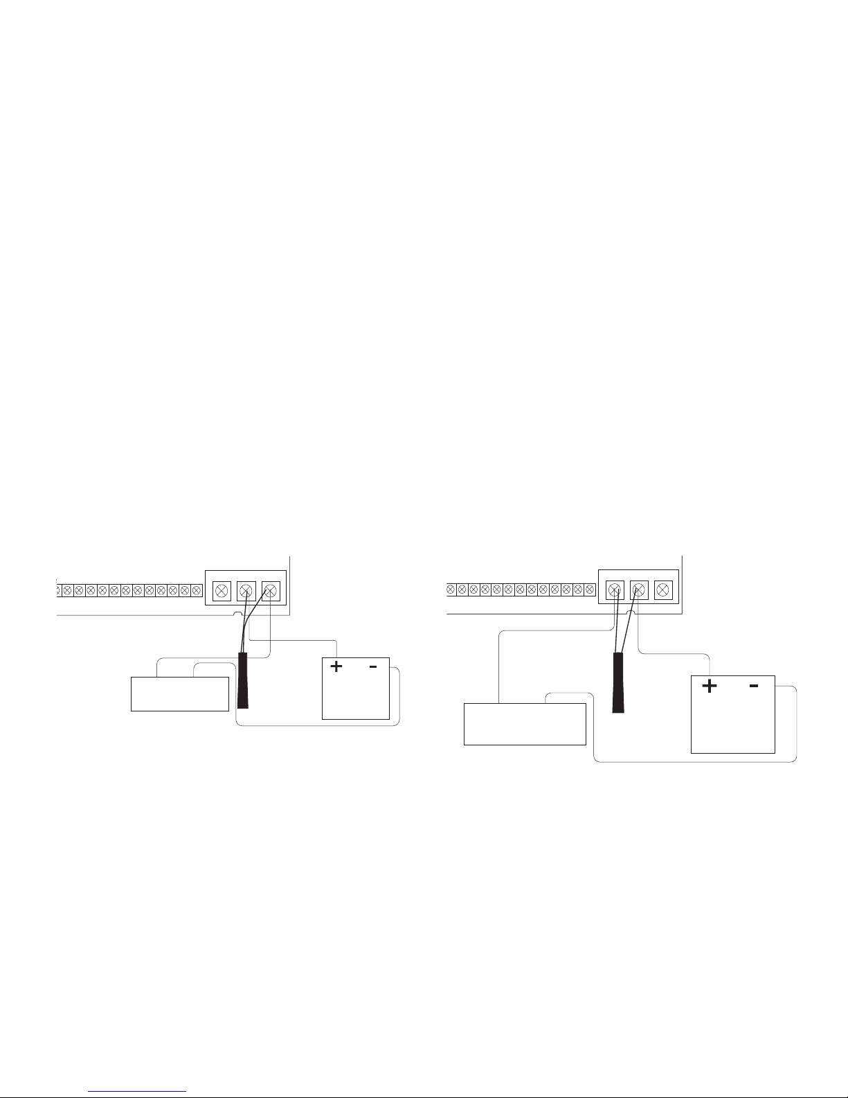
Use a power supply to power magnetic locks. See Figure 3. You can power door strikes either
from a power supply (DRY contact) or from the 1134 (WET contact). See Figures 4a and 4b for
door strike wiring.
The Form C relay draws up to 35mA of current and contacts are rated for 10Amps (resistive)
at 12/24VDC. When connecting multiple locks to the Form C relay, the total current for all locks
cannot exceed 10 Amps. If the total current for all locks exceeds 10 Amps, problems may arise
and an isolation relay may be needed. See the Isolation Relay section for information.
2
WIRE THE ELECTRONIC LOCK
3
4 5 6 7
8
10
11 12 13 14
9
LC AS
GRN BLK Z1 Z2 Z3 Z4RA GND GNDGND
NC
C
NO
Model 333
Suppressor
–
+
Magnetic Door Lock
12/24 VDC
Power Supply
Normally Closed
Figure 3: Typical
Magnetic Lock Wiring
Figure 4a: Dry Door
Strike Wiring
Page 12

8 1134 Installation and Programming Guide | Digital Monitoring Products, Inc.
234 5 6 7
8
10
11 12 13 14
9
LC AS
GRN BLK Z1 Z2 Z3 Z4RA GND GND
NC
C
NO
Model 333
Suppressor
–+
DC Door Strike
Normally Open
GND
When the jumper on the 1134 is set to WET, the C terminal will pass 12VDC though the
Cterminal. No additional power supply is needed. See Figure4b.
Figure 4b: Wet
Door Strike Wiring
Page 13

Digital Monitoring Products, Inc. | 1134 Installation and Programming Guide 9
The Form C relay can control a device that draws less than 10 Amps of current. If a device draws
more than 10 Amp of current, or the sum of all devices controlled by the Form C relay exceeds
10 Amps, an isolation relay must be used. Refer to Figures 5 and 6 for isolation relay wiring.
3
ISOLATION RELAY
7
8
10
11 12 13 14
9
AS Z1 Z2 Z3 Z4
GND GND
NC
C
NO
Model 333
Suppressor
Normally Open
–+
Magnetic Lock
–+
Isolation Relay
12/24 VDC
Power
Supply
NCCNO
GND
Figure 5: Magnetic Lock with
an Isolation Relay
5
6 7
8
10
11 12 13 14
9
LC
AS Z1 Z2 Z3 Z4RA GND GND
NC
C
NO
Model 333
Suppressor
Normally Open
–+
DC Door Strike
–+
Isolation Relay
12/24 VDC
Power
Supply
NCCNO
GND
Figure 6: Door Strike with
an Isolation Relay
(optional)
Page 14

10 1134 Installation and Programming Guide | Digital Monitoring Products, Inc.
Use the included 333 suppressor with the
1134 to suppress any surges caused by
energizing a magnetic lock or door strike.
Install the 333 across the 1134 C (common)
and NO (normally open) or NC (normally
closed) terminals.
If the device being controlled by the relay is
connected to the NO and C terminals, install
the suppressor on the NO and C terminals.
Conversely, if the device is connected to
the NC and C terminals, install the 333
Suppressor on NC and C terminals.
The suppressor wire is non-polarized. Install
the suppressor as shown in Figure 7.
4
INSTALL THE 333 SUPPRESSOR
8
10
11 12 13 14
9
Z1 Z2 Z3 Z4GND GND
NC
C
NO
GND
Figure 7: 333 Suppressor
Installation on the 1134
Page 15

Digital Monitoring Products, Inc. | 1134 Installation and Programming Guide 11
Terminals 8 through 14 connect grounded zones 1 through 4. These zones have a grounded side
and cannot be used for fire-initiating devices. Zones 2 and 3 can also be used for access control
with zone 2 providing a bypass feature and zone 3 providing Request to Exit functionality.
Use the supplied 311 1K Ohm end-of-line (EOL) resistors on each zone. Refer to the panel
programming guide for programming instructions. See the table below and Figure 8 for more
information on wiring the zone terminals.
5
WIRE THE ZONE TERMINALS
ZONE # RECOMMENDED DEVICE
1 Any burglary device
2 Door Contact
3 REX (PIR or Button)
4 Any burglary device
Table 1: 1134 Zone Uses
Page 16

12 1134 Installation and Programming Guide | Digital Monitoring Products, Inc.
1
2
3
4 5 6 7
8
10
11 12 13 14
9
LC ASRED WHT GRN BLK Z1 Z2 Z3 Z4RA GND GND
NC
C
NO
Zone 1
Zone 2
Zone 3
Zone 4
1K EOL
1K EOL
1K EOL
1K EOL
GND
Figure 8: 1134 Zone Terminal
Wiring
Page 17

Digital Monitoring Products, Inc. | 1134 Installation and Programming Guide 13
The 1134 provides direct 12/24VDC, 200mA output to the reader on the RED terminal
connection. Figure 9 shows a reader with wire colors RED, WHT, GRN, and BLK connecting to
terminals 1, 2, 3, and 4.
The green wire carries Data Zero (D0), and the white wire carries Data One (D1). The red wire
connects 12/24VDC, 200mA maximum power and the black wire is ground.
The wire colors may be dierent depending on the reader being installed. Refer to the literature
provided with the reader for wire coding, wire distance, cable type (such as shielded), and other
specifications.
Card Reader LED Operation
To provide visual indication of a valid card read, the card reader can be wired to illuminate the
green LED for the duration of the door strike.
Connect the orange or brown wire to LC terminal 5 to have the green LED stay on for the
duration of the relay activation.
Card Reader Annunciation
Connect the yellow wire to RA terminal 6 to have the remote annunciator turn on anytime the
panel instructs the 1134 on-board piezo to turn on.
6
CONNECT A CARD READER
(optional)
Page 18

14 1134 Installation and Programming Guide | Digital Monitoring Products, Inc.
Figure 9: Card Reader Wiring
1
2
3
4 5 6 7
8
10
11 12 13 14
9
LC ASRED WHT GRN BLK Z1 Z2 Z3 Z4RA GND GND
NC
C
NO
PROG
Card Reader
Red (12/24VDC)
White (Data 1)
Black (GND)
Green (Data 0)
Shield
Orange/Brown
Yellow
GND
Page 19

Digital Monitoring Products, Inc. | 1134 Installation and Programming Guide 15
PROGRAM THE 1134 OPTIONS
When you program the 1134, you can use a keypad connected to the 1134 programming header and
set to address 1. For 12V applications, connect the keypad to the module using a Model 330 4-wire
harness. For 24V applications, connect the keypad to the module using a Model 330-24 4-wire
programming harness with in-line resistor.
Do not connect a keypad using a standard Model 330 harness if using a 24V power supply!
Damage to the keypad could occur.
While the 1134 is in programming mode, it will not be able to communicate with the panel.
PROGRAM START DISPLAY
When you connect the keypad to the 1134 module, the version number
and release date display. Press CMD to enter the PROGRAMMER
menu.
SERIAL NUMBER DISPLAY
View the serial numbers for the 1134. The 1134 has a Type14 and
Type08 serial number. Press CMD to view the second serial number.
INITIALIZATION OPTION
These options can set the 1134 module programming memory back to
factory defaults. Press any select key or area to enter the Initialization
menu.
1134 PROGRAMMING
VER VVV MM/DD/YY
SERIAL#:XXXXXXXX
INITIALIZE ALL?
NO YES
Page 20

16 1134 Installation and Programming Guide | Digital Monitoring Products, Inc.
INITIALIZE CONFIRM OPTION
After selecting YES to clear the Access Options, the 1134 displays
SURE? YES NO for confirmation to clear the memory. This is a
safeguard against accidentally erasing the programming. No memory
is cleared from the programming until you answer YES to the SURE?
option. Selecting NO leaves communication options unchanged.
ACTIVATE ZONE 2 BYPASS
Select YES to activate the zone 2 bypass operation. Selecting NO
allows standard zone operation on zone 2. The default is NO.
If the door being released by the 1134 module is protected (contact
installed), a programmable bypass entry/exit timer can be provided
by connecting the contact wiring to the 1134 module zone 2. When
the on-board Form C relay activates and the user opens the door
connected to zone 2, the zone is delayed for the number of seconds
programmed in ZONE 2 BYPASS TIME allowing the user to enter/exit
during an armed period.
If zone 2 does not restore (door closed) within the programmed time,
the piezo sounds every other second during the last ten seconds.
If zone 2 restores prior to the end of the programmed time, the
piezo silences. If the zone does not restore before the programmed
time, the 1134 ends the bypass and indicates the open or short zone
condition to the panel.
ARE YOU SURE?
YES NO
ACTIVATE ZONE 2
BYPASS? NO YES
Page 21

Digital Monitoring Products, Inc. | 1134 Installation and Programming Guide 17
ZONE 2 BYPASS TIME
Enter the number of seconds to elapse before the bypass timer
expires. The range is 20-250 seconds. Press any select key or area to
enter the number of seconds. The default is 40seconds. Figure12
shows how the bypass option works.
RELOCK ON ZONE 2 CHANGE
Selecting YES turns the relay o when zone 2 changes state.
Selecting NO leaves the relay on when zone 2 changes state.
Turning o the relay at Door Closed allows a long strike time to be
automatically ended and relocks the door. The default is NO.
ZONE 2 BYPASS
TIME: 40
5 Second
Strike
40-Second Zone 2 Bypass
entry/exit timer.
10 seconds before
the bypass time expires,
the device beeps if
the door is still open.
End of
timer.
40
Seconds
A zone open/short is
indicated if the door
remains open.
Figure 12: Zone 2 Bypass Timeline using default time
RELOCK ON ZONE 2
CHANGE? NO YES
Page 22

18 1134 Installation and Programming Guide | Digital Monitoring Products, Inc.
ACTIVATE ZONE 3 REQUEST TO EXIT
Selecting YES activates the zone 3 Request to Exit (REX) option.
Selecting NO allows standard zone operation on zone 3. Default
setting is NO.
Connect a motion sensing device or a mechanical switch to zone 3 to
provide REX capability to the system.
When zone 3 shorts, the on-board Form C relay activates for the
programmed number of seconds. See Zone 3 REX Strike Time.
During this time, the user can open the protected door to start the
programmed zone 2 bypass entry/exit timer. After the programmed
number of seconds, the relay restores the door to its locked state.
The 1134 module provides a bypass-only option for REX on zone 3.
When zone 3 OPENS from a NORMAL state, only a bypass occurs: the
on-board relay does not activate. This bypass-only option uses two
methods of REX.
The first REX device provides the programmed bypass entry/exit
timer. The second REX unlocks the door.
ACTIVATE ZONE 3
REX? NO YES
Page 23

Digital Monitoring Products, Inc. | 1134 Installation and Programming Guide 19
ZONE 3 REX STRIKE TIME
Enter the number of REX seconds to elapse. Range is from 5 to 250
seconds. Press any select key or area to enter the number of seconds.
The default is 5 seconds.
ACTIVATE ONBOARD SPEAKER
Select YES to enable the onboard piezo for local annunciation, such
as alarm and trouble annunciations. Select NO to turn the speaker
o for all operations. This does not aect remote annunciator open
collector (RA) operation. The default is NO.
ZN 3 REX STRIKE
TIME: 5
ACTIVATE ONBOARD
SPEAKER? NO YES
Page 24

20 1134 Installation and Programming Guide | Digital Monitoring Products, Inc.
CUSTOM CARD DEFINITIONS
ANY CARD FORMAT
Select YES to allow all card reads to activate the door strike relay. The
door strike relay is activated for the length of time programmed in
ZN3 REX TIME. No user code information is sent to the panel. Default
is NO.
CARD FORMATS
Select the slot number (1-7) that you would like to program a custom
non-DMP card format into. Select 8 if you would like to program a
DMP card format. See Public Card Formats for some publicly available
card formats that can be used with the 1134. Other private or custom
formats may also be compatible. Please contact the credential
supplier or manufacturer for the bit structure.
FORMAT NAME
Press any select area to rename the card format. Press CMD to save
and advance.
ANY CARD FORMAT
NO YES
CARD FORMATS
FORMAT NO: -
FORMAT NAME
*UNUSED*
Page 25

Digital Monitoring Products, Inc. | 1134 Installation and Programming Guide 21
01110101101101010001100111
First Bit
Received
Position = 0
Site Code
Position = 1
Length = 8
User Code
Position = 9
Length = 16
Last Bit
Received
Position = 25
In this example the Wiegand Code Length = 26 bits.
Figure 13: Wiegand Data Stream Bit
Location
WIEGAND CODE LENGTH
When using a custom credential, enter the total number of bits to be
received in Wiegand code including parity bits.
Press any select key or area to enter a number between 1-255 to equal
the number of bits. Default is 26 bits.
An access card contains data bits for a site code, user code, and
start/stop/parity bits. The starting position, location, and code length
must be determined and programmed into the keypad. See Figure13.
WEIGAND CODE
LENGTH: 26
Page 26

22 1134 Installation and Programming Guide | Digital Monitoring Products, Inc.
SITE CODE POSITION AND LENGTH
Enter the site code start position and length in the data string. Press
select area 2 to clear the site code start position and enter a number
between 0-255. Press CMD to save. Default is 1.
Press select area 4 to clear the site code length and enter a number
between 1-24. Press CMD to save. Default is 8.
USER CODE POSITION AND LENGTH
Define the user code start bit position and length. Press select area 2
to clear the user code position and enter a number between 0-255.
Press CMD to save. Default is 9.
Press select area 4 to clear the user code length and enter a number
between 16-64. Press CMD to save. The default is the DMP value of 16.
REQUIRE SITE CODE
Press the top row select key or area under YES to use a site code and
press CMD to view the site code entry display. Press NO to advance to
NO OF USER CODE DIGITS. Default is NO.
In addition to user code verification, door access is only granted when
any one site code programmed at the SITE CODE ENTRY option
matches the site code received in the Wiegand string.
SITE CODE
POS: 1 LEN: 8
USER CODE
POS: 9 LEN: 16
REQUIRE SITE
CODE?: NO YES
Page 27

Digital Monitoring Products, Inc. | 1134 Installation and Programming Guide 23
SITE CODE DISPLAY
You can program up to eight 8-digit site codes. The site code range is
0-16,777,214.
In the keypad display, enter site code 1 and press CMD. The display
will ask for site code 2 followed by site code 3 and so on. When you
have selected the site code you want to change, press CMD.
NUMBER OF USER CODE DIGITS
The 1134 module recognizes user codes from 4-12digits long. Press
any top row select key or area to enter a user code digit length. This
number must match the user code number length being programmed
in the panel. Default is 5.
All bits are read and converted into a decimal number string. The
number string is left padded with ‘0’ if needed for long user code
lengths. When selecting ‘4’ the right digit is dropped and the next
four sent.
Example: # decoded 1234567
10 digits 0001234567
5 digits 34567
4 digits 3456
SITE CODE 1:
NO OF USER CODE
DIGITS: 5
Page 28

24 1134 Installation and Programming Guide | Digital Monitoring Products, Inc.
NO COMMUNICATION WITH PANEL
Define the relay action when communication with the panel has not
occurred for 5seconds. Default is OFF. Press any select key or area to
change the default relay action:
Press the first select key or area to choose OFF (Relay Always O) —
The relay and Wiegand LED do not turn on when any Wiegand string
is received. OFF does not aect any REX operation. If communication
is lost during a door strike, the relay remains on for the door strike
duration but turns o at the end of the door strike timer.
Press the second select key or area to choose SITE (Accept Site
Code) — Door access is granted when the Wiegand site code string
received matches any site code programmed at SITE CODE DISPLAY.
Refer to REQUIRE SITE CODE for more information.
Press the third select key or area to choose ANY (Any Wiegand Read)
— Access is granted when any Wiegand string is received.
Press the fourth select key or area to choose ON (Relay Always On) —
The relay is always on.
Press CMD to display the next action.
Press the first select key or area to choose LAST (Keep Last State)
— The relay remains in the same state and does not change when
communication is lost.
NO COMM WITH PNL
OFF SITE ANY ON
NO COMM WITH PNL
LAST
Page 29

Digital Monitoring Products, Inc. | 1134 Installation and Programming Guide 25
REMOVE KEYPAD
The REMOVE KEYPAD option continually displays with no time
out while the keypad remains connected to the 1134 module after
programming is finished. After five seconds, the 1134 module
piezo continually sounds if the keypad remains connected and
programming is finished. Remove the keypad harness to disconnect
the keypad from the 1134 module and silence the alarm.
REMOVE KEYPAD
Page 30

26 1134 Installation and Programming Guide | Digital Monitoring Products, Inc.
PUBLIC CARD FORMATS
CARD
FORMAT
WIEGAND
CODE
LENGTH
SITE
CODE
POSITION
SITE
CODE
LENGTH
USER
CODE
POSITION
USER
CODE
LENGTH
USER
CODE
DIGITS
H10301 26 BIT 26 1 8 9 16 5
H10302 37 BIT
W/FAC
37 1 16 17 19 6
H10304 37 BIT
W/O FAC
37 0 0 1 35 12
FARPOINTE
39 BIT
39 1 17 18 20 7
CORPORATE
1000 35 BIT
35 2 12 14 20 6
CORPORATE
1000 48 BIT
48 2 22 24 23 7
Page 31

Digital Monitoring Products, Inc. | 1134 Installation and Programming Guide 27
PRODUCT SPECIFICATIONS
Primary Power 8.5VDC to 28.5VDC
Current Draw
Standby 220mA (includes 200mA for proximity reader)
Peak 230mA (includes 200mA for proximity reader)
Reader Current up to 200mA
Zones 5VDC, 2mA max
Dimensions 4.5W x 2.75H x 1.75Din
11.43W x 7H x 4.45Dcm
Weight 8oz .23kg
Page 32

28 1134 Installation and Programming Guide | Digital Monitoring Products, Inc.
READERS AND CREDENTIALS
125 KHZ PROXIMITY READERS
P-300 CASCADE PROXIMITY
READER
P-500 ALPS PROXIMITY READER
P-640 PATAGONIA PROXIMITY
READER WITH KEYPAD
MP-5365 MINIPROX™ PROXIMITY
READER
MX-5375 MAXIPROX® PROXIMITY
READER
PP-6005B PROXPOINT® PLUS
PROXIMITY READER
PP-5355 PROXPRO PROXIMITY
READER WITH KEYPAD
PR-5455 PROXPRO® II PROXIMITY
READER
TL-5395 THINLINE II® PROXIMITY
READER
125 KHZ PROXIMITY CREDENTIALS
PSC-1 STANDARD LIGHT
PROXIMITY CARD
PSK-3 PROXIMITY KEY
RING TAG
PSM-2P ISO IMAGEABLE
PROXIMITY CARD
1306 PROX PATCH™
1326 PROXCARD II®
CARD
1346 PROXKEY III®
ACCESS DEVICE
1351 PROXPASS®
1386 ISOPROX II® CARD
Page 33

Digital Monitoring Products, Inc. | 1134 Installation and Programming Guide 29
13.56 MHZ SMARTCARD READERS
DELTA3 FARPOINTE SMARTCARD
READER
DELTA5 FARPOINTE SMARTCARD
READER
DELTA5.3 FARPOINTE SMARTCARD
READER
DELTA6.4 FARPOINTE SMARTCARD
READER
13.56 MHZ SMARTCARD CREDENTIALS
DC1-1 FARPOINTE CLAMSHELL
SMARTCARD
DM1-3 FARPOINTE IMAGEABLE
SMARTCARD
DE2 FARPOINTE MIFARE®
DESFIRE® EV1
SMARTCARD
DK1-3 FARPOINTE KEY FOB
SMARTCARD
Page 34

30 1134 Installation and Programming Guide | Digital Monitoring Products, Inc.
FCC INFORMATION
This device complies with Part 15 of the FCC Rules. Operation is subject to the following two
conditions:
1. This device may not cause harmful interference, and
2. This device must accept any interference received, including interference that may cause
undesired operation.
Changes or modifications made by the user and not expressly approved by the party responsible for
compliance could void the user’s authority to operate the equipment.
Note: This equipment has been tested and found to comply with the limits for a Class B digital
device, pursuant to part 15 of the FCC Rules. These limits are designed to provide reasonable
protection against harmful interference in a residential installation. This equipment generates,
uses and can radiate radio frequency energy and, if not installed and used in accordance with the
instructions, may cause harmful interference to radio communications. However, there is no guarantee
that interference will not occur in a particular installation. If this equipment does cause harmful
interference to radio or television reception, which can be determined by turning the equipment o
and on, the user is encouraged to try to correct the interference by one or more of the following
measures:
• Reorient or relocate the receiving antenna.
• Increase the separation between the equipment and receiver.
• Connect the equipment into an outlet on a circuit dierent from that to which the receiver is
connected.
• Consult the dealer or an experienced radio/TV technician for help.
Page 35

Digital Monitoring Products, Inc. | 1134 Installation and Programming Guide 31
This device complies with Industry Canada Licence-exempt RSS standard(s). Operation is subject to
the following two conditions:
1. This device may not cause interference, and
2. This device must accept any interference, including interference that may cause undesired
operation of the device.
Le présent appareil est conforme aux CNR d’Industrie Canada applicables aux appareils radio
exempts de licence. L’exploitation est autorisée aux deux conditions suivantes:
1. l’appareil ne doit pas produire de brouillage, et
2. l’utilisateur de l’appareil doit accepter tout brouillage radioélectrique subi, même si le brouillage
est susceptible d’en compromettre le fonctionnement.
INDUSTRY CANADA INFORMATION
Page 36

LT-1889 19134 © 2019 Digital Monitoring Products, Inc.
 Loading...