

DMP Electronics 1100XHE, 1100XE, 1100XH Installation Manual
1100XHE ENCRYPTED HIGH POWER
WIRELESS RECEIVER
Installation Guide
PROGRAM THE PANEL
Refer to the panel programming guide as needed.
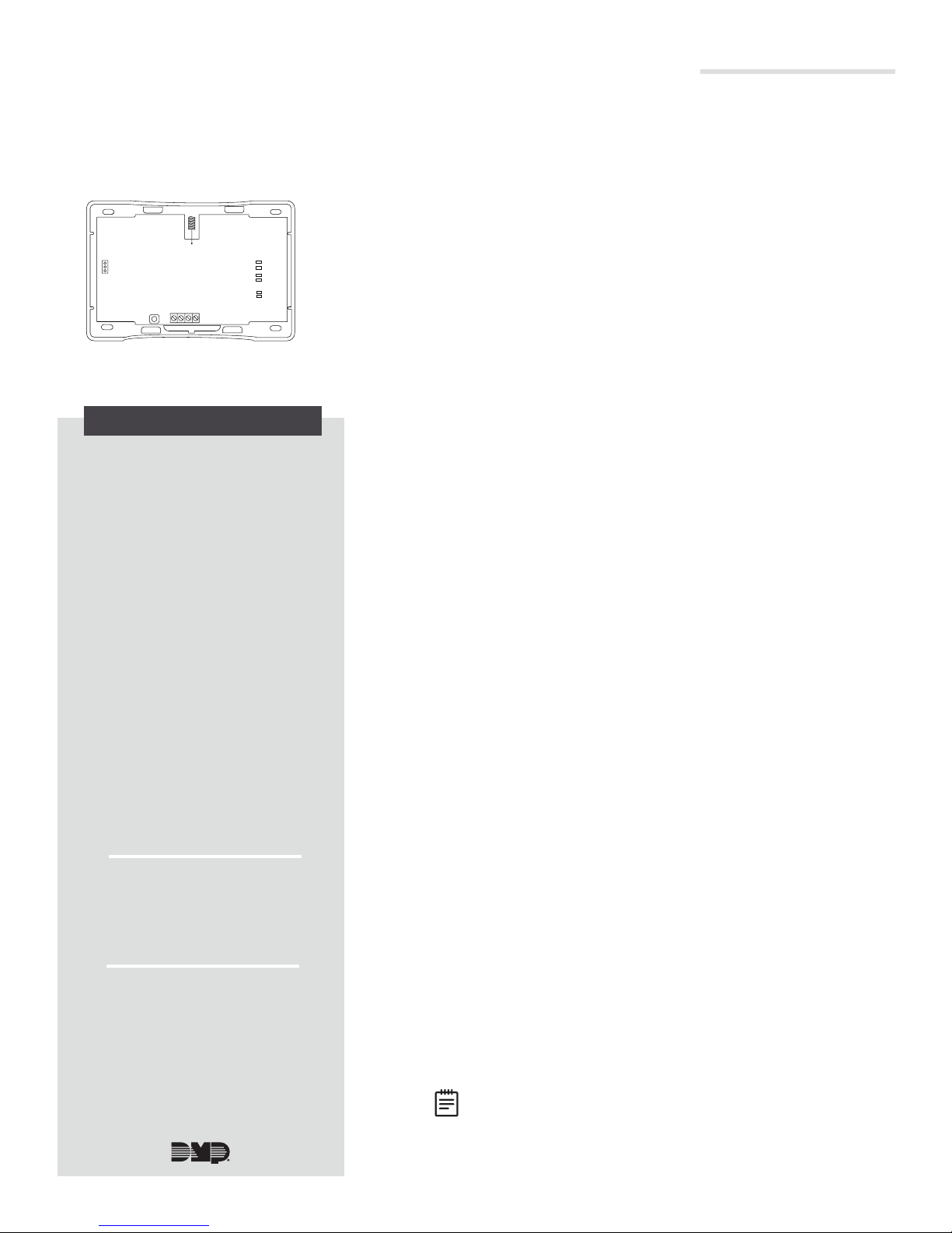
WALL
TAMPER
ENABLE
DISABLE
Figure 1: 1100XHE
Encrypted High Power
Wireless Receiver
RF RX
RF TX
PANEL RX
PANEL TX
STATUS
PWR
DESCRIPTION
The 1100XHE Encrypted High Power
Wireless Receiver provides up to
100 wireless zones for XR150 Series
panels and up to 500wireless
zones for XR550Series
panels. The 1100XHE features
128-bitAESencryption.
The 1100XHE provides two-way,
supervised communication using
900MHz frequency hopping-
spread-spectrum technology.
The 1100XHE contains additional
transmit and receive amplifiers to
enable 1100 Series operation at
greater distances or harsh building
environments. The additional gain
introduced by this amplification
may inhibit proper communication
with 1100 Series transmitters
located within 4ft of the receiver.
This distance may be 8ft when
using the 1122 PIR or 9000 Series
Wireless Keypads.
The 1100XHE is equipped with a
case and wall tamper.
Compatibility
• XR150/XR550 Series Panels
• Encryption requires panel
Version 183 or higher
What is Included?
• One 1100XHE Encrypted
High Power Wireless
Receiver
• Hardware Pack
1
2
3
1. Reset the panel.
2. At a keypad, enter 6653 (PROG) to access the
PROGRAMMER menu.
3. In SYSTEM OPTIONS, program a HOUSE CODE between
1 and 50. See House Code Explained for more information.
4. At the 1100 ENCRYPTION prompt, select ALL to only add
encrypted wireless devices to the system. Select BOTH to
allow both encrypted and non-encrypted wireless devices
to be programmed.
5. The default passphrase appears at ENTER PASSPHRASE.
Press CMD to keep the default. Press any select key or
area to change the passphrase and enter an 8-character
hexadecimal string (0-9, A-F).
6. In ZONE INFORMATION, enter a ZONE NAME and press
CMD.
7. Select the ZONE TYPE and press CMD.
8. At NEXT ZN?, select NO.
9. Select YES when WIRELESS? displays.
10. Enter the eight-digit SERIAL# and press CMD.
11. Enter the SUPRVSN TIME and press CMD.
12. At the NEXT ZN? prompt, select YES to finish
programming or select NO for additional programming
options.
MOUNT THE 1100XHE
Select a Location
When selecting a location to mount the 1100XHE, keep in mind
that the receiver should be centrally located between the
1100Series transmitters used in the installation. The 1100XHE
can be mounted up to 500ft (150m) from the panel using
22AWG or 1000ft (300m) using 18AWG. Be sure to mount
the receiver away from large metal objects because it may
impair the receiver’s performance. Do not use shielded wire
between the panel and receiver.
Mount the 1100XHE
1. Remove the cover from the plastic housing.
2. Use the included #6 screws to secure the 1100XHE to
the wall. See Figure 2 for mounting hole locations.
WIRE THE 1100XHE
Connect the red, yellow, green, and black wires to the PANEL
terminal on the 1100XHE and connect the other to the XBUS
terminal on the panel. See Figure 2.
Note: The receiver can’t operate if it’s connected to the
keypad bus.
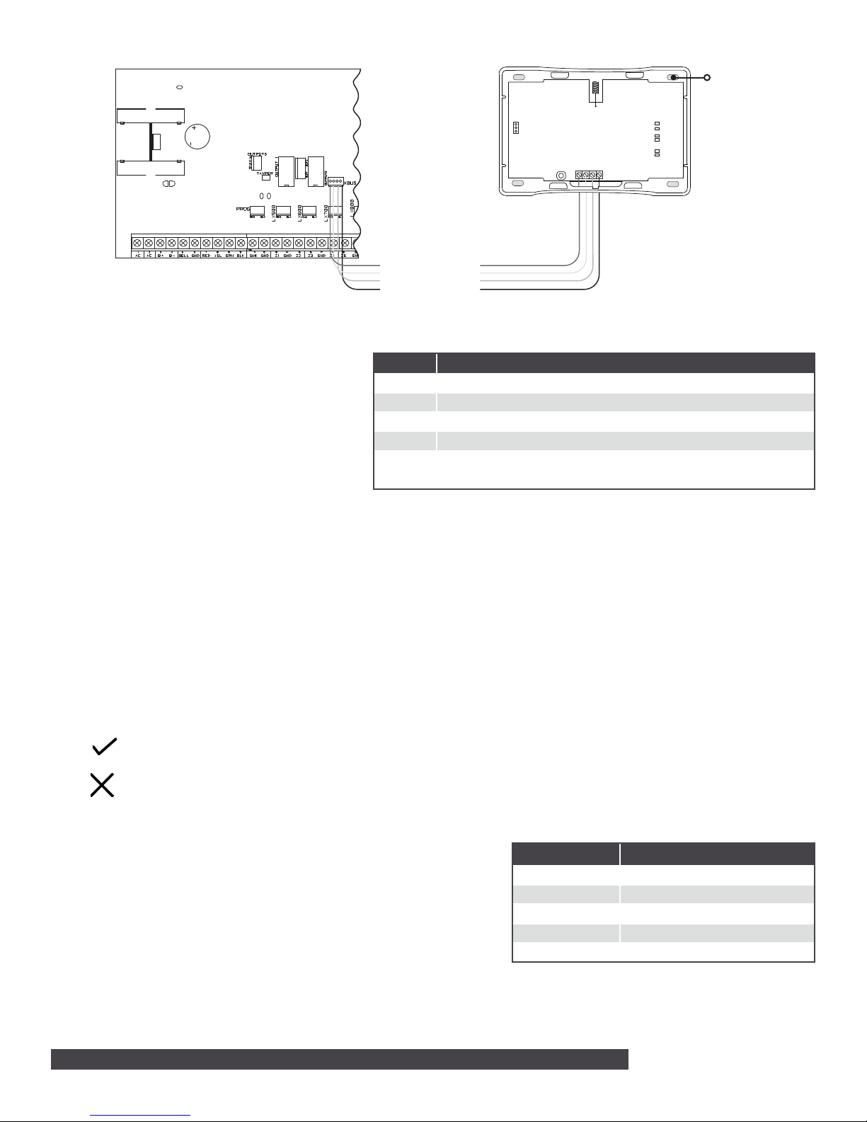
Power LED
Battery Start
XR150/XR550
XMT - Transmit LED
Series Panel
REC - Receive LED
Figure 2: Wiring The 1100XHE to the Panel
ADDITIONAL INFORMATION
Can be extended up to
500 ft from the panel using
22 AWG or 1,000 ft using
18 AWG
WALL
TAMPER
ENABLE
DISABLE
1100XHE
Receiver
PANEL
RF RX
RF TX
PANEL RX
PANEL TX
STATUS
PWR
Mounting Hole
1100XHE LED Operation
The six labeled LEDs on the 1100XHE PCB
display wireless receiver operation and activity.
See Figure 2 for LED locations and Table 1 for
LED indications.
House Code Explained
The house code identifies the panel, receiver,
and transmitters to each other. The 1100XHE
automatically sends the specified house code
LED INDICATIONS
RF RX Flashes yellow to indicate data is being received from a transmitter.
RF TX Flashes green to indicate data is being sent to a transmitter.
PANEL RX Flashes yellow to indicate data is being received from a panel.
PANEL TX Flashes green to indicate data is being sent to the panel.
STAT US Solid red to indicate memory is being uploaded. Turns o when complete.
PWR Solid green to indicate there is power to the wireless receiver.
Table 1: 1100XHE LED Indications
to wireless transmitters when transmitter serial
numbers are programmed into the panel. The
1100XHE only listens for transmissions using the
specified house code or the programmed transmitters’ serial numbers.
LED Survey Operation for 1100 Series Transmitters
1100 Series transmitters provide a survey operation that allows one person to confirm that each transmitter is
communicating with the wireless receiver or panel to easily determine the best location. Follow the directions below to
test communication of the wireless transmitters:
1. Remove the transmitter’s cover.
2. Hold the transmitter in the exact desired location.
3. Press the tamper switch to send data to the wireless receiver and determine if communication is confirmed or
faulty.
Confirmed: If communication is confirmed, the survey LED turns on when data is sent to the wireless receiver
and o when acknowledgment is received.
Faulty: If communication is faulty, the LED remains on for several seconds or flashes multiple times in quick
succession. Relocate the transmitter or the wireless receiver until the LED confirms clear communication.
Proper communication between the transmitter and wireless receiver is verified when for each press or
release of the tamper switch, the transmitter’s LED blinks immediately on and immediately o.
Programming Zones
Refer to the panel XR150/XR550 Series Programming Guide (LT-1232)
for complete wireless programming information. When any wireless
input zone for a particular address is programmed, the 1100XHE
responds to the panel for this address. Other devices, such as
keypads or hardwired zone expanders, cannot use this address. Zones
connected directly to the panel cannot be wireless. See Table 2 for
designated zone numbers.
2 1100XHE WIRELESS RECEIVER | DIGITAL MONITORING PRODUCTS
ZONE NUMBERS DESIGNATIONS
400-449 1144 Wireless Key Fobs
450-479 Slow Response Outputs (15 sec.)
480-499 Fast Response Outputs (1 sec.)
500-599 Wireless Devices (XR150)
500-999 Wireless Devices (XR550)
Table 2: Zone Number Designations
 Loading...