

Page 1
INSTALLATION NOTE
U5
1
J5
1
RED
J4
1
PROG
PANEL
J3
1
RED
Power
RXD
TXD
Status
RF RXD
RF TXD
U8
1
J4
1
U4
1
U7
J1
1
AC
12345678 10 11 12 13 14 15 169
+B BELL GND SMK GNDRED YEL GRN BLKZ1Z2Z3AC –B GND G
K6 K7
Output 1 Output 2
J10
J22
LX
Battery
Start
J23
J21
RS-232
Power
LED
J8
PROG
Out1 Out2
J2
XR100/XR100FC/XR500/XR500FC
Series Panel
R
L
X
Black
Green
Yellow
Red
Can be extended
up to 1000 feet
from the panel
Red
1100X
Receiver
J4 Not Used
XMT - Transmit LED
REC - Receive LED
1100X Wireless Receiver Quick Install
Installation
This Installation Note provides a quick review of the steps necessary to connect an 1100X Wireless Receiver to an
XR500 Series panel. As needed refer to the XR500 Series Install Guide (LT-0681), XR500 Series Programming Guide
(LT-0679), and the 1100X Install Guide (LT-0708).
1. On the XR500 Series panel, Install a jumper across the pins next to the letter “X” on the J23 Header.
2. Connect one end of the included 4-wire harness to the XR500 panel 4-pin header labeled J22 LX and run a
cable up to 1000’ to connect to the J3 header on the 1100X Wireless Receiver. This provides up to 500 wireless
zones numbered 500 to 999. A location should be selected that will be centrally located between the 1100
Series transmitters used in the installation. Install the receiver away from large metal objects. Mounting the
receiver on or near metal surfaces impairs performance. Do not use shielded wire between the panel and
receiver. When selecting the proper mounting location of a transmitter, refer to the LED Survey Operation
section of the specic installation guide for the transmitter being installed.
Note: The 1100X Wireless Receiver cannot operate if connected to the Keypad Bus.
3. Reset and restart the panel using the J16 jumper to activate the DMP Wireless Bus operation.
4. In System Options, program the House Code (1-50). In Zone Information, program the wireless zones.
Note: Do not operate transmitter devices with a battery until all wireless zones are programmed in the XR500
panel.
5. Save the changes by running the Stop routine to exit the keypad programmer or, if using Remote Link,
disconnect from the panel. Wait one minute after saving programming to memory, then test the wireless
zones.
Troubleshooting
Should wireless devices not operate, refer to the following checklist:
• Verify the XR500 panel J23 jumper is in the “X” position.
• Briey reset the panel using the J16 jumper to activate
wireless operation.
• Verify the House Code (1-50) is programmed in System
Options.
• Verify the 4-wire connector from the receiver is
connected to J22.
J23
R
L
X
Place Jumper
on DMP Wireless
Bus "X" header pins.
• Wait one minute after reset to test wireless zone(s).
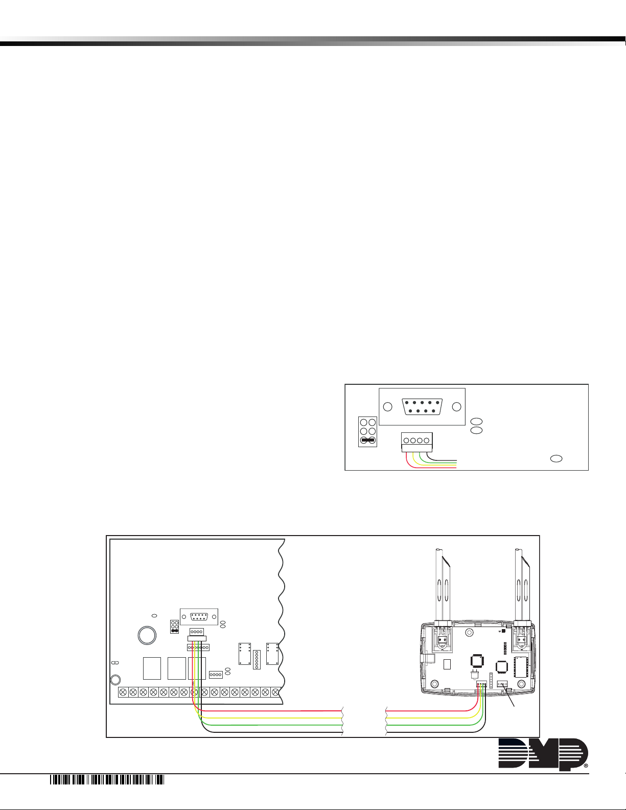
Diagrams
The gure to the right shows detailed XR500 Series panel connections.
The gure below shows the XR500 Series Panel and the 1100X Wireless Receiver connection.
J21
RS-232
J22
LX
Connect 4-wire Harness
XMT - Transmit LED
REC - Receive LED
Overcurrent
(OVC) LED
LT-0918 1.01 © 2007 Digital Monitoring Products, Inc.
7395
Page 2

Contents
Installation 1
Troubleshooting 1
Diagrams 1
 Loading...