

Page 1
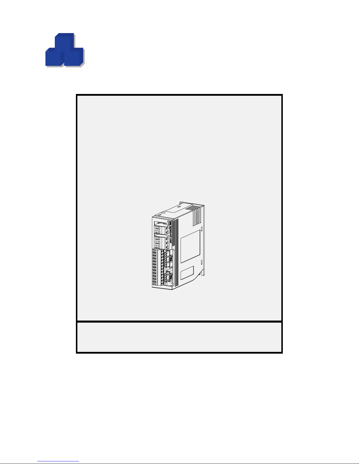
DYN2 Series
M
M
D
Dynamic Motor Motion
Technology Corporation
AC Servo Drive
Type - A General-Purpose Pulse/Analog
Specication Manual
Manual Code
Revision
This manual must be kept available for the user
Copyright © 2014 DMM Technology Corp.
Published In Canada
: DYN2MS-01E-0814A1
: A1
Hardware Version
Firmware Version
: AH10
: AH10
Page 2
■ Safety Notice ■
!
The user or operator should read through this manual completely before installation, testing, operation, or
inspection of the equipment. The DYN2 series AC Servo Drive should be operated under correct circumstances and conditions. Bodily harm or damage to equipment and system may result if specications
outlined in this document are not followed. Take extra precaution when the warning convention is used.
■ Notations Used ■
All specication and units of measurement used in the manual are in METRIC:
Mass: Kilogram [kg]
Length: Millimeter [mm]
Time: Seconds [s]
Temperature: Celsius [C]
WARNING
DYN2MS-01E-0814A1
2
Page 3

Product Manual Preface
The user or operator should read through this manual completely before installation, testing, operation,
or inspection of the equipment. The DYN2 series AC Servo Drive should be operated under correct
circumstances and conditions. Bodily harm or damage to equipment and system may result if specications outlined in this document are not followed. Take extra caution at details when the warning
convention is used.
This manual is available on the DMM Technology Corp. website. A physical copy or reference to the
on-line availability must be kept convenient to the servo drive user or operator for references.
Contact DMM Technology Corp. if the user or operator has any questions or concerns regarding use.
The DYN2 AC Servo Drive is not designed or certied to implement safety into a system and should
not be used in applications where the servo drive maintains safety to personnel or machine.
To reect improvements, additions, revisions, changes or corrections made to the product or manual,
this document is updated accordingly and divided into revisions to reect each version.
DYN2MS-01E-0814A1
3
Page 4

Manual Contents
Safety Notice 2
Notations Used 2
Product Manual Preface 3
Manual Contents 4
A.1 Introduction 5
A.2 Name Plate 5
A.3 Servo Drive Model Number 5
1 GENERAL SPECIFICATION 6
1.1 Drive Overall Specication 6
1.2 Control Block Diagram 7
1.3 Encoder Specication 7
2 CONNECTIONS AND WIRING 8
2.1 DYN2 Servo Drive Body Layout 8
2.2 Connector and Signal Specication 9
2.3 JP3 Main I/O Details 11
2.4 JP3 I/O Connection Circuit 15
2.5 Main Power Supply Requirements 19
3 START UP 20
3.1 Mounting and Installation 20
3.2 Timing Chart 21
3.3 DMMDRV Software Communication 23
4 OPERATION 24
4.1 Position Servo Mode 24
4.2 Speed Servo Mode 27
4.3 Torque Servo Mode 29
4.4 RS232 Command Input Mode 30
4.5 Absolute Zero Position Index Output (ZRI) 30
5 PARAMETERS AND TUNING 31
5.1 Parameters Outline 31
5.2 Servo Drive Gain Tuning 33
6 MAINTENANCE 35
6.1 Alarm Specications 35
6.2 Drive Maintenance 36
APPENDIX A - SERVO DRIVE DIMENSIONS 37
APPENDIX B - RS232 Protocol Denition 38
APPENDIX C - Operation Examples 39
Warranty and Liability 40
Product and Manual Disclaimer 41
DYN2MS-01E-0814A1
4
Page 5
A.1 Introduction
This manual documents all features and specications for the DYN2 series AC Servo Drive Type A General Purpose Pulse/Analog. The servo drive features standard pulse train and analog command input
modes compatible with universal motion controllers, PLC’s or CNC controllers. Control modes include position, speed or torque servo mode with standard signal connections and interfacing for seamless integration into any system. A high resolution 16-bit (65,536pulse/rev) encoder combined with outstanding 10ms
instantaneous position response optimizes performance in high-demand applications.
Gain adjustment is simplied with 3 parameter tuning for fast and easy adjustments while maintaining critical application and response exibility. All testing and tuning is done through a RS232 or USB interface
with a host PC running DMMDRV GUI software for fast and easy set up. Drive status is internally monitored by 22 parameters for consistent and reliable performance.
Standard servo motor and encoder/motor power cable pair options available. Measuring only 32mm [W] x
85mm [H] x 75mm [D], the DYN2 AC Servo drive can power up to 0.75kW (7.1Nm) capacity. The perfect
servo drive for any small to medium capacity application.
A.2 Name Plate
Note the name plate is region specic and may vary between each region model.
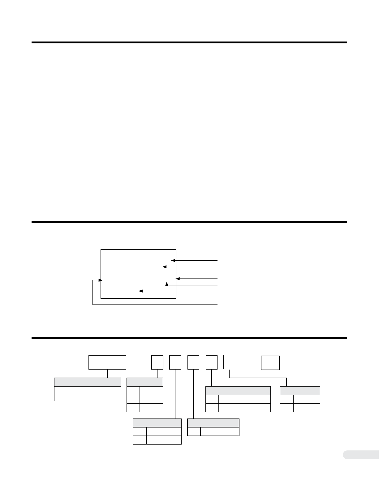
A.3 Servo Drive Model Number
DYN2 - T L A 6 S - 00
DMM Servo Drive Series
DYN2 AC Servo Drive
Low Voltage DC Input
Voltage Class
T 60V
H 48V
S 24V
Model Number
Input / Output Specications
Protection
Country of Origin
Lot / Serial Number
Hardware / Software Version
Encoder
4 14bit [16,384ppr]
6 16bit [65,536ppr]
Model Type
S Standard
** Custom
DYN2MS-01E-0814A1
Motor Capacity
1 50W - 200W
L 400W - 750W
Command Type
A Pulse / Analog
5
Page 6
1 GENERAL SPECIFICATION
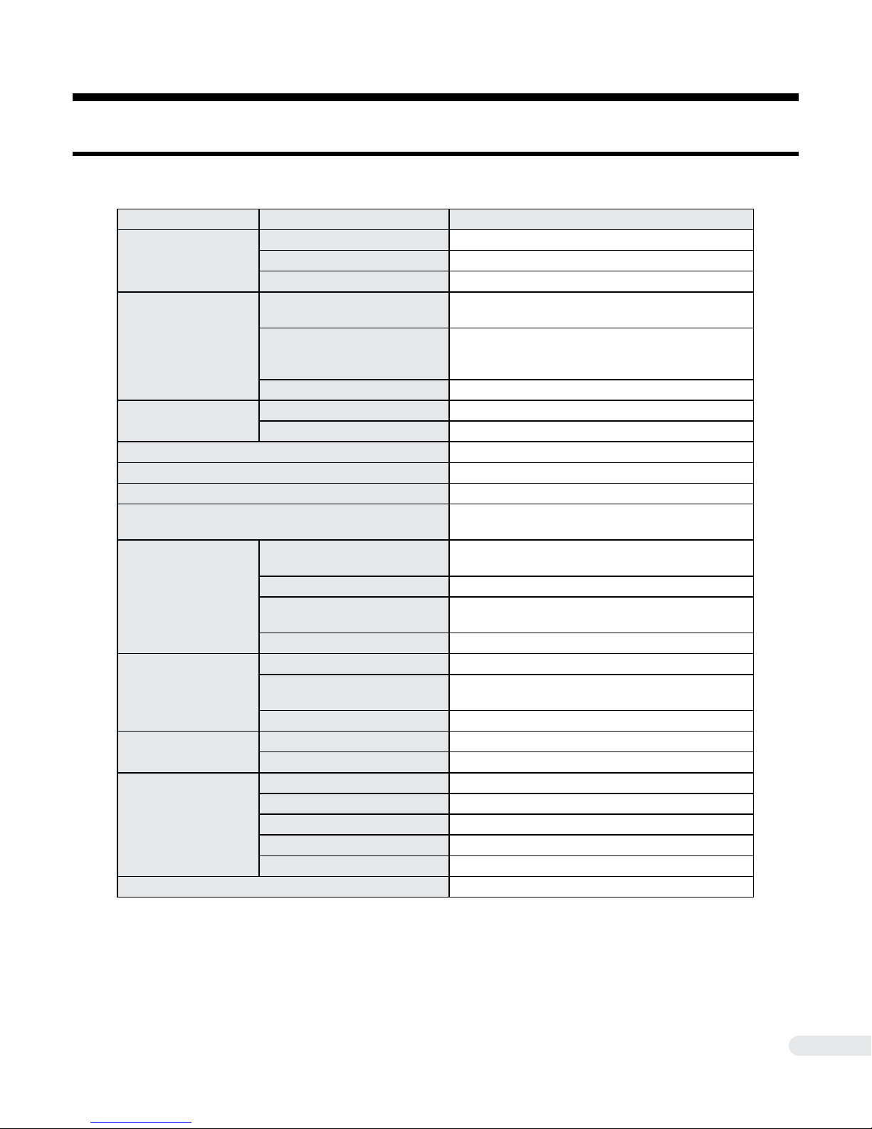
1.1 Drive Overall Specication
Data Specication
Rated Voltage 60VDC ± 10%
Input
Output
Drive Interface Power
Supply (JP2 Pin. 12)
Control Method SVPWM
Dynamic Brake Integrated
Encoder Feedback 14/16-bit Single-Turn Absolute
Protection Functions
Position Servo
Speed Servo
Torque Servo
Environment
Mass 0.2kg
Permissible Input Voltage 24VDC ~ 75VDC
Rated Current 16A
Rated Voltage
Rated Current
Motor Capacity 50W ~ 750W
Voltage 5VDC +/-%5
Max. Current Draw 50mA
Command Reference Pulse*1
Max. Input Frequency 500kHz
Input Voltage
Positioning Feedback Z Index Pulse*2
Speed Control Range 0:5000
Input Reference Voltage
Max Input Voltage ± 12VDC
Input Reference Voltage -10VDC ~ +10VDC ± %5
Max Input Voltage ± 12VDC
Protection IP10
Operation Temperature 0~55°C
Storage Temperature -20 ~ 65°C
Max. Operation Humidity 95RH% (no dew)
Max. Storage Humidity 95RH% (no dew)
Peak. +75VAC
Between any two motor phase
[L] Capacity Model: Peak. 20A
[1] Capacity Model: Peak 10A
From any single motor phase
Current, Voltage, Temperature, Over Power, Position Lost Follow
Pulse+Sign, A/B Phase Quadrature 90° Phase
Differential, CW+CCW
5VDC ± %5 (Higher voltage available as option)
Over drive photocoupler diode
-10VDC ~ +10VDC ± %5
3,000rpm at ± 5VDC
1. CW+CCW command format available as option.
2. See section 4.5 for Z index pulse details
DYN2MS-01E-0814A1
6
Page 7
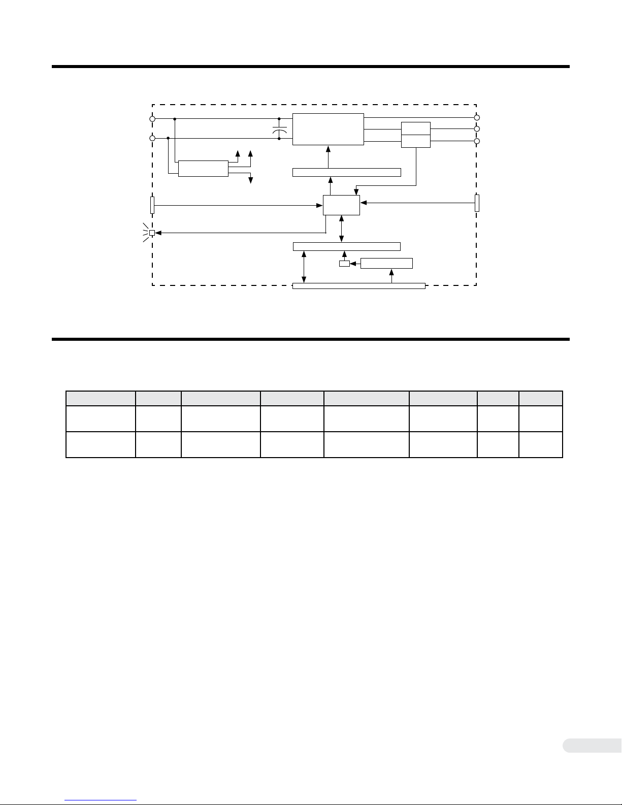
1.2 Control Block Diagram
DYN2 AC Servo Drive
Main Power
Input
+
-
Switching
Power Supply
+15VDC
+5VDC
Main Control
Inverter Circuit
Isolated Gate Control
Current
Sensor
Current
Sensor
A
B
C
RS232
Serial Port
LED S1
JP2
CPU
Isolated I/O Interface
Analog Input
A/D
Voltage Protection
JP4
JP3
Encoder
Feedback
1.3 Encoder Specication
■ Model
Model Number Type Resolution Data Type Interface Type Measurement Voltage Status
ABS-14-00 Absolute 14bit [16,384ppr] 4-Wire Serial
ABS-16-00 Absolute 16bit [65,536ppr] 4-Wire Serial
Differential Driver/
Receiver
Differential Driver/
Receiver
Magnetic +5VDC A
Magnetic +5VDC A
DYN2MS-01E-0814A1
7
Page 8
2 CONNECTIONS AND WIRING
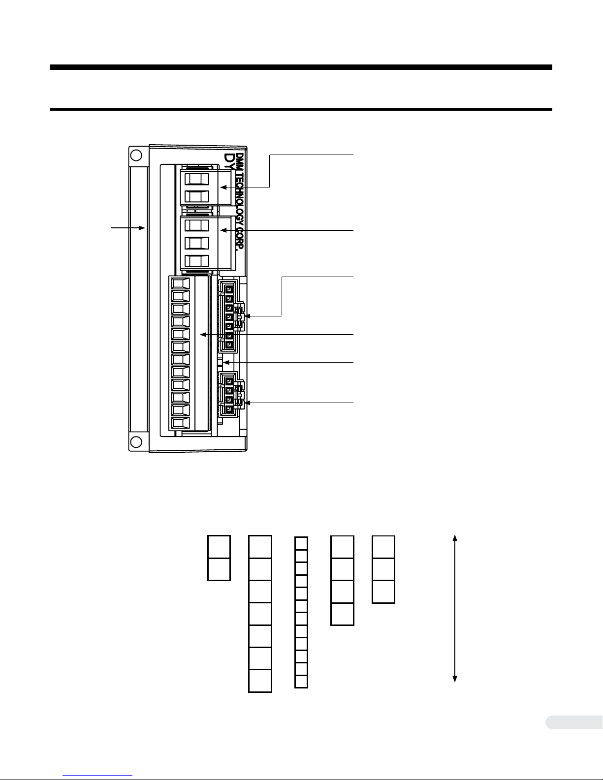
2.1 DYN2 Servo Drive Body Layout
■ JP1
Power Supply Input
(1)
■ Pin Layout
■ JP5
Servo Motor Power
■ JP2
RS232 Port to PC
■ JP3
I/O Port
■ S1 Drive Status LED
[ Green LED ]
■ JP4
Encoder Feedback Port
(1) Drive Body Grounding Terminal
[ M3 x 5mm Max. ]
*Located on left side of body
DO NOT reverse JP1 DC
input polarity!
DYN2MS-01E-0814A1
JP1
+
-
JP2
Gnd
NC
NC
NC
RxD
TxD
+5V
JP3
12
11
10
9
8
7
6
5
4
3
2
1
JP4
Gnd
S-
S+
+5V
JP5
C
B
A
Top side of servo drive
Bottom side of servo drive
8
Page 9

2.2 Connector and Signal Specication
▐ JP1 - Power Supply Input
Connector Type: 5.00mm Pitch Terminal Block
Drive Header: Phoenix MSTBA 2,5/ 2-G
Plug Connector: Phoenix MSTB 2,5/ 2-ST
2
Recommended Wire Gauge: 0.8mm
▐ JP2 RS232 Port to PC
Connector Type: 2.54mm Pitch Rectangular
Drive Header: Molex 70553-0041
Plug Connector: Molex 50-57-9407
Recommended Wire Gauge: 0.3mm
Signal Layout:
Pin 1: GND
Pin 2~4: NC
Pin 5: RS232 signal input, RxD, TTL/CMOS level.
Pin 6: RS232 signal output, TxD, TTL/CMOS level.
Pin 7: +5(V) output, <10(mA), generated in board.
(AWG18)
2
(AWG22)
In order to connect JP2 with PC’s RS232 port, an intermediate cable with level shift buffer is necessary.
Intermediate cable shipped with drive tuning cable [Model No. CA-MRS232-6].
▐ JP3 I/O Port - Position Command Input
Connector Type: 3.5mm Pitch Terminal Block
Drive Header: Phoenix MC 1,5/12-G-3,5
Plug Connector: Phoenix MC 1,5/12-ST-3,5
2
Recommended Wire Gauge: 0.6mm
(20AWG)
Signal Layout:
Pin 1: GND (Bottom side of drive)
Pin 2: Analog Command Reference ±10VDC
Pin 3: DIR-, B-, CCW- Pulse Reference
Pin 4: DIR+, B+, CCW+ Pulse Reference
Pin 5: STEP-, A-, CW- Pulse Reference
Pin 6: STEP+, A+, CW+ Pulse Reference
Pin 7: Signal Common for Pin. 8, 9, 10, 11.
Pin 8: Alarm Output
Pin 9: OnPosition Output
Pin 10: Absolute Zero Position Index Output
Pin 11: Drive Disable Input
Pin 12: Drive Internal +5VDC Supply (Top side of drive nearest to JP5)
DYN2MS-01E-0814A1
9
Page 10

▐ JP4 Encoder Feedback Port
Connector Type: 2.54mm Pitch Rectangular
Drive Header: Molex 70553-0038
Plug Connector: Molex 50-57-9404
2
Recommended Wire Gauge: 0.3mm
(AWG22)
Signal Layout:
Pin 1: +5VDC Supply
Pin 2: S+
Pin 3: S-
Pin 4: Gnd
▐ JP5 Servo Motor Power
Connector Type: 5.00mm Pitch Terminal Block
Drive Header: Phoenix MSTBA 2,5/ 3-G
Plug Connector: Phoenix MSTB 2,5/ 3-ST
2
Recommended Wire Gauge: 0.8mm
(AWG18)
Signal Layout:
Pin 1: A Phase
Pin 2: B Phase
Pin 3: C Phase
2.2 Connector and Signal Specication
Motor frame should be grounded through Drive Body Grounding Terminal [ M3 ] located on heat sink side.
Crimp an M3 terminal lug onto the servo motor frame wire (Yellow/Green) and attach the lug to the drive
body grounding terminal. Do not use a screw longer than 5mm.
DYN2MS-01E-0814A1
10
Page 11
2.3 JP3 Main I/O Details
!
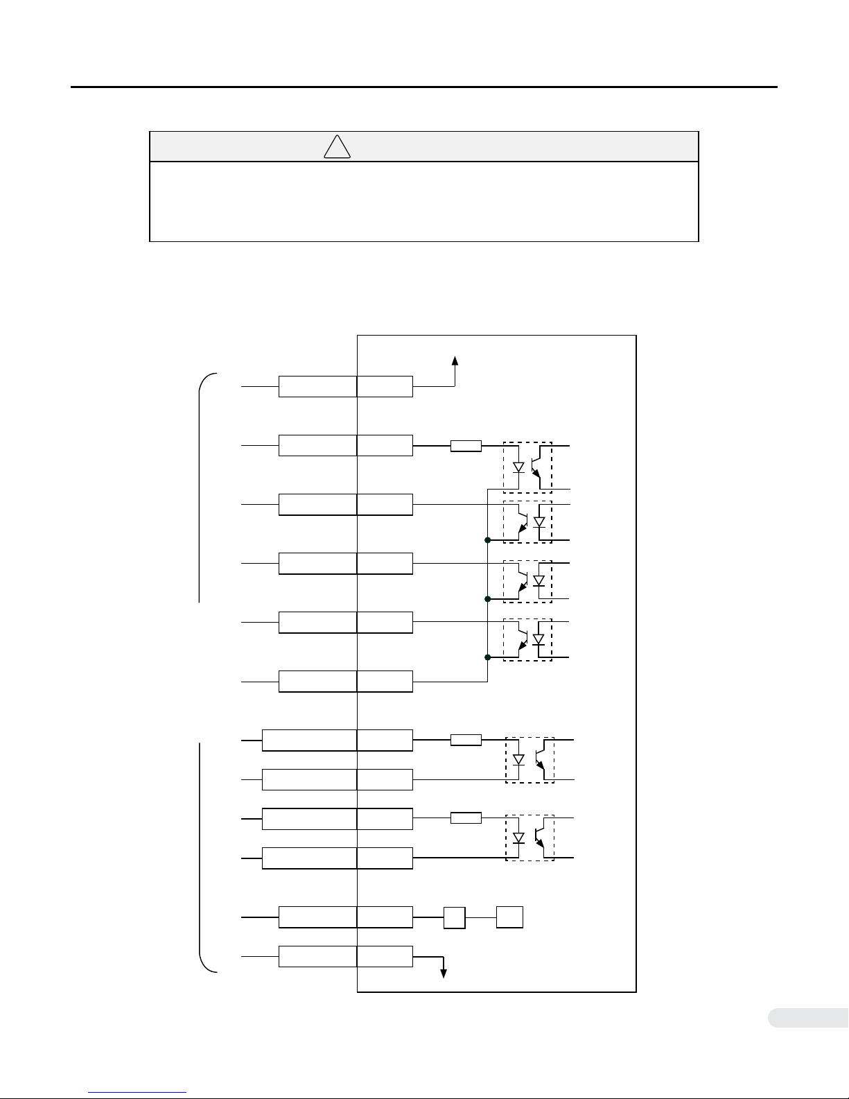
● Note the directionality of the JP3 connector and pins before making connections. Pin1
is located nearest to the bottom of the servo drive. Pin12 is located nearest terminal JP5
(Servo Motor Power).
■ Terminal Layout
WARNING
DYN2 Servo Drive
Drive internal +5VDC
+5VDC
ENA
ZRI
ONPOS
ALM
COM
( Host Controller )
PUL+, A+, CW+
PUL-, A-, CW-
12
270Ω
11
10
9
8
7
270Ω
6
5
DIR+, B+, CCW+
DIR-, B-, CCW-
DYN2MS-01E-0814A1
AGIN
GND
4
270Ω
3
2
A/D
1
11
Page 12
2.3 JP3 Main I/O Details
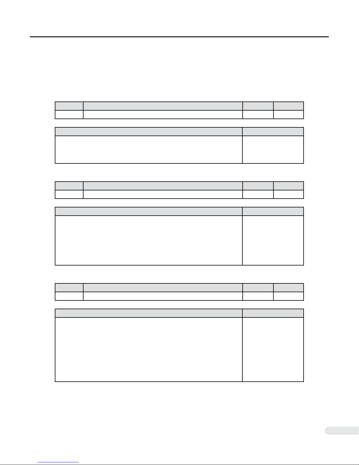
■ JP3 Signal Specication
Refer to Section 2.4 JP3 I/O Connection Circuit for example connection diagram. Standard I/O
levels are +5VDC±%10. Contact DMM if the controller uses 12~24VDC level I/O.
Pin No. Signal Symbol Type
12 Drive Internal +5VDC Supply +5VDC Output
Description Connection Circuit
- Drive internal +5VDC output
- Max Current Draw: 50mA
- Relative ground side with JP3 Pin.1
Pin No. Signal Symbol Type
11 Drive Disable Input ENA Input
N/A
Description Connection Circuit
- Apply +5VDC between Pin.7 Common to Disable servo drive
- Motor coasts when disabled (shaft free)
- Disable clears all pulse/analog commands
- Disable clears all position error
- Max. Voltage: +5VDC±%10
- Max. Current: 20mA
Pin No. Signal Symbol Type
10 Absolute Zero Position Index Output ZRI Output
Description Connection Circuit
- Transistor ON (Signal LOW) if servo on Zero Position.
- Triggered at signal falling edge
- Zero Position output xed to one mechanical motor shaft position per revolution. Accuracy maintained by absolute encoder.
- Used for precision zeroing, or indexing applications.
- Max. Voltage: 30V
- Max. Current: 30mA
[ A ]
*See section 2.4
[ B ]
*See section 2.4
DYN2MS-01E-0814A1
12
Page 13
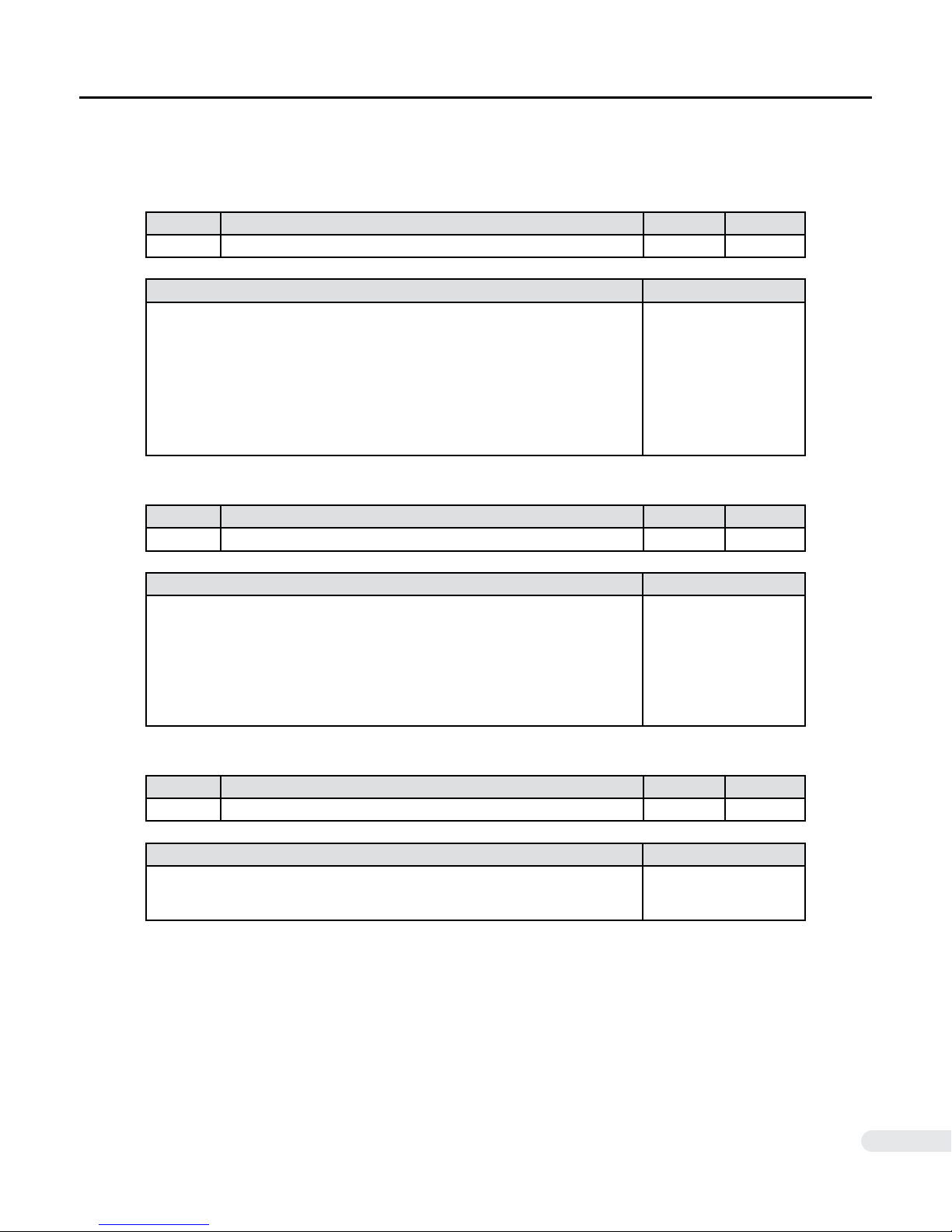
2.3 JP3 Main I/O Details
Refer to Section 2.4 JP3 I/O Connection Circuit for example connection diagram.
Pin No. Signal Symbol Type
9 OnPosition Output ONPOS Output
Description Connection Circuit
- Transistor ON (Signal LOW) if servo Off Position.
- Transistor OFF (Signal HIGH) if servo On Position.
- Servo On Position if motor position error within value set by OnPosRange
parameter.
- Max. Voltage: 30V
- Max. Current: 30mA
Pin No. Signal Symbol Type
8 Servo Alarm ALM Output
[ B ]
*See section 2.4
Description Connection Circuit
- Transistor ON (Signal LOW) if servo drive alarmed or faulted
- Servo drive triggers protective alarm relative to Current, Voltage, Temperature, Over Power, Position Lost Follow
- Max. Voltage: 30V
- Max. Current: 30mA
Pin No. Signal Symbol Type
7 Common COM Output
Description Connection Circuit
- JP3 I/O Pin. 8, 9, 10, 11 Control Signal Common.
[ B ]
*See section 2.4
[ A ] [ B ]
*See section 2.4
DYN2MS-01E-0814A1
13
Page 14
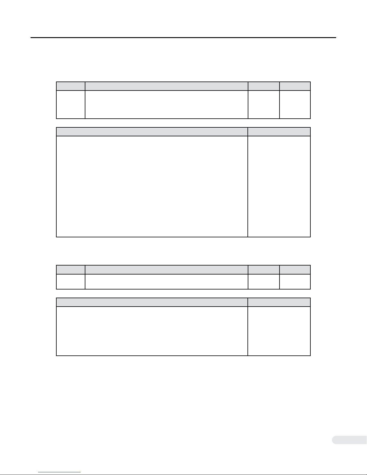
2.3 JP3 Main I/O Details
Refer to Section 2.4 JP3 I/O Connection Circuit for example connection diagram.
Pin No. Signal Symbol Type
6
5
4
3
Description Connection Circuit
- Position command reference pulse input
- Compatible pulse form include:
♦ Pulse + Direction
♦ A/B phase quadrature with 90° phase differential
♦ CW + CCW
- Max. input pulse frequency: 500kHz
- Max. Voltage: +5VDC±%10
- Max. Current: 20mA
- Line Drive / Open Collector circuit on Controller Side
- Input pulse electronically scalable with GEAR_NUM parameter
STEP+, A+, CW+ Pulse Reference
STEP-, A-. CW- Pulse Reference
DIR+, B+. CCW+ Pulse Reference
DIR-, B-. CCW- Pulse Reference
STEP+
STEPDIR+
DIR-
[ C ]
*See section 2.4
Input
Pin No. Signal Symbol Type
2
1
Description Connection Circuit
- Analog command reference for Speed/Torque servo mode
- Voltage reference ±10VDC
- ±12VDC max input voltage
- Max current: 0.6mA
DYN2MS-01E-0814A1
Analog Command Reference
Ground
AGIN
GND
[ D ]
*See section 2.4
Input
N/A
14
Page 15
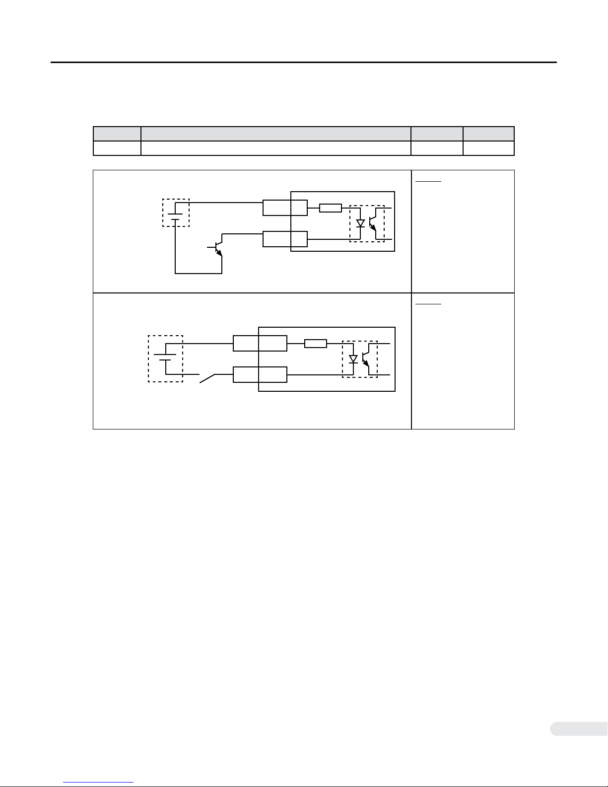
2.4 JP3 I/O Connection Circuit
■ Type [ A ] Connection Circuit - General Input Circuit
Applicable Signals:
Pin No. Signal Symbol Type
11 Drive Disable Input ENA Input
Open Collector Notes:
+5VDC
ENA
COM 7
11
270Ω
- Sink circuit shown.
Source circuit can also
be used.
Relay/Switch
+5VDC
ENA
COM 7
Notes:
270Ω
11
DYN2MS-01E-0814A1
15
Page 16
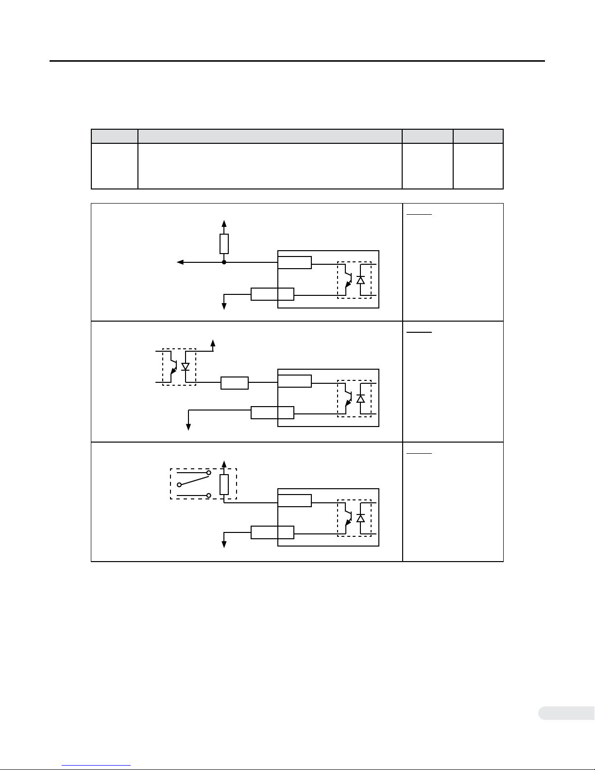
2.4 JP3 I/O Connection Circuit
■ Type [ B ] Connection Circuit - General Output Circuit
Applicable Signals:
Pin No. Signal Symbol Type
10
9
8
7
Absolute Zero Position Index Output
OnPosition Output
Servo Alarm
Common
ZRI
ONPOS
ALM
COM
Output
Output
Output
N/A
Collector Output Notes:
Photo Coupler
Relay
+5VDC
+5VDC
5~24VDC
1kΩ
10, 9, 8
COM 7
Notes:
1kΩ
10, 9, 8
COM 7
Notes:
DYN2MS-01E-0814A1
10, 9, 8
COM 7
16
Page 17
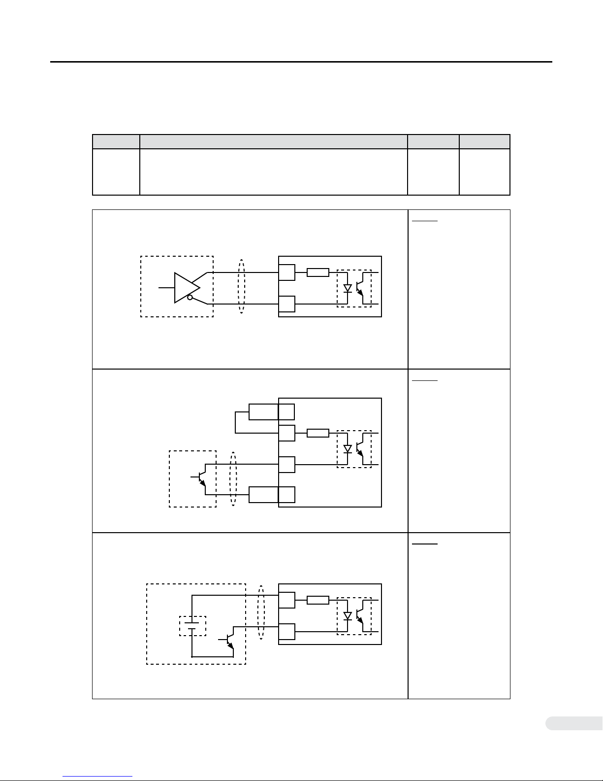
2.4 JP3 I/O Connection Circuit
■ Type [ C ] Connection Circuit - Position Reference Pulse Input
Applicable Signals:
Pin No. Signal Symbol Type
6
5
4
3
Line Driver Notes:
STEP+, A+, CW+ Pulse Reference
STEP-, A-. CW- Pulse Reference
DIR+, B+. CCW+ Pulse Reference
DIR-, B-. CCW- Pulse Reference
6, 4
5, 3
270Ω
STEP+
Input
STEPDIR+
DIR-
- Twisted pair cable with
shield grounded on
receiver side.
Open Collector
(DYN2 Internal Power Supply)
Open Collector
(External Power Supply)
+5VDC
12+5VDC
6, 4
5, 3
1GND
6, 4
5, 3
270Ω
270Ω
Notes:
- Twisted pair cable with
shield grounded on
receiver side.
Notes:
- Power supply provided by host controller or
external source.
- Twisted pair cable with
shield grounded on
receiver side.
DYN2MS-01E-0814A1
17
Page 18
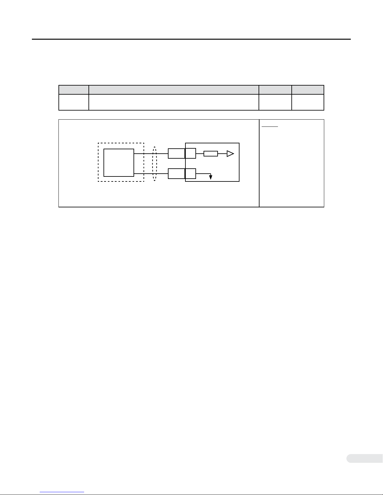
2.4 JP3 I/O Connection Circuit
■ Type [ D ] Connection Circuit - Analog Command Reference Input
Applicable Signals:
Pin No. Signal Symbol Type
2
1
Analog Command Reference
Ground
D/A Converter
Op-amp
Potentiometer
etc.
AGIN
GND
AGIN
GND
Input
N/A
Notes:
- Twisted pair cable with
shield grounded on
receiver side.
2
1
DYN2MS-01E-0814A1
18
Page 19
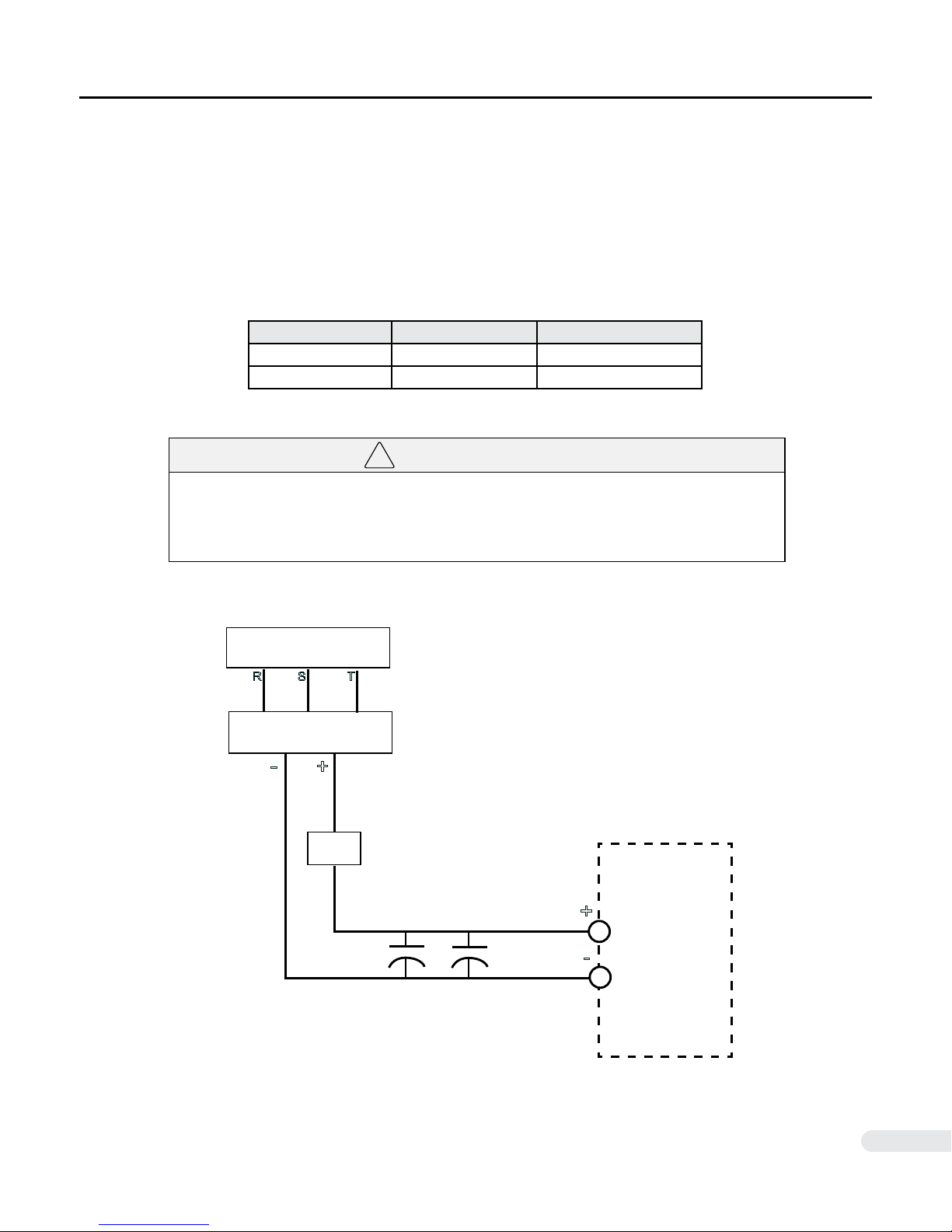
2.5 Main Power Supply Requirements
!
The DYN2 servo drive has a minimum operation input of +24VDC and max input of +75VDC. The servo
drive’s internal over-voltage alarm is triggered at +80VDC input and will shut down at this level. Consider
the voltage/speed gradient of the servo motor when selecting power supplies.
A smoothing (reservoir) capacitor is recommended after the DC power supply. The recommended capacity
is 100V 1,000uF. Connect a fuse before the servo drive according to the circuit size.
Servo Drive Model Max. Motor Capacity Recommended Fuse
DYN2-T1A6S-00 200W 20A
DYN2-TLA6S-00 750W 20A
● DO NOT reverse the polarity of the DC input power. Reversing the polarity will permanently damage the servo drive and may cause electric shock. Ensure polarity is correct
before powering ON the servo drive.
WARNING
110~240VAC Supply
R S T
AC-DC Power Supply
-
+
Fuse
1000uF
100V
1000uF
100V
DYN2 Servo Drive
JP1
+
-
DYN2MS-01E-0814A1
19
Page 20
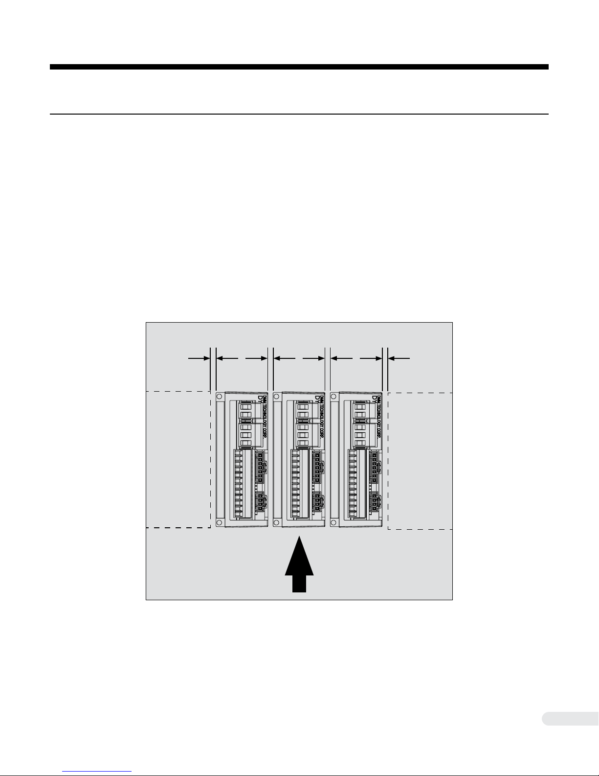
3 START UP
3.1 Mounting and Installation
The DYN2 servo drive can be mounted vertically or horizontally (vehicle mount). The servo drives should
be mounted by its rear chassis to an electrically conductive metal panel or plate. When mounting multiple
servo drives, at least 1mm clearance should be left between each unit. The small size of the DYN2 servo
drive is compatible with modular mounting. It can be placed adjacent to other devices with 1mm clearance. Also consider the size of the connectors and cables in front of the servo drive when mounting.
The control cabinet internal temperature should not exceed 40°C. If using a fan to cool the servo drives,
the air ow should parallel the direction of the heat sink n. The servo drive internally do not have a cooling fan.
(Other Devices)
>1mm >1mm
Airow
Direction
>1mm>1mm
(Other Devices)
DYN2MS-01E-0814A1
20
Page 21
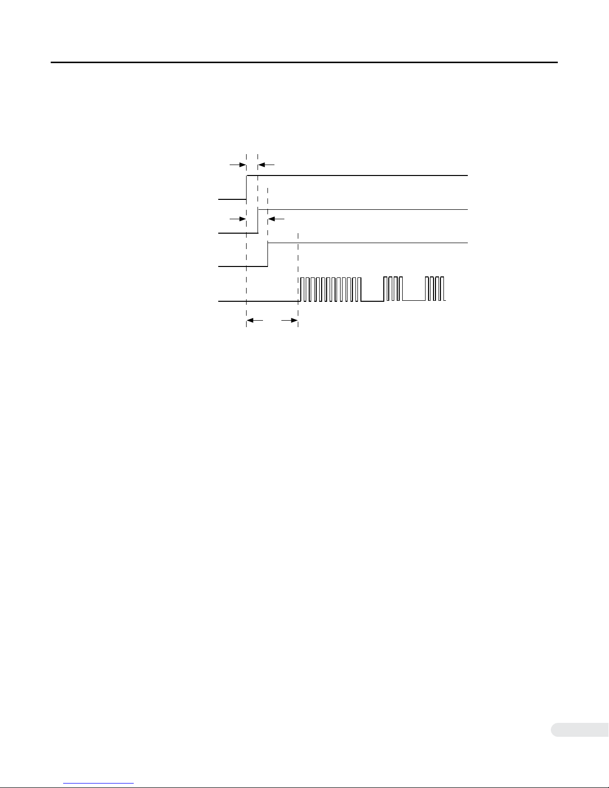
3.2 Timing Chart
■ Power ON Timing
After servo drive power ON, make sure there is at least 150ms time before sending pulse or analog command to servo drive.
Main Power Supply
50ms
ON
S1 Status LED
Servo ON
(Motor Servo Lock)
Command Reference
Input Pulse/Analog
OFF
ON
OFF
ON
OFF
HIGH
LOW
Status LED lit Green
100ms
150ms
Normal Operation
♦ Main Power Supply Cycle
Do not cycle the main power supply quickly as internal power electronics may be permanently damaged.
The main power should be turned on once during each operation cycle and should not be controllable by
software.
♦ Power Off Residual Voltage
After drive power off, the user should wait 60 seconds before touching the servo drive. A residual voltage
may remain in the servo drive after immediate power off and 60 seconds is needed for full discharge. This
time may be longer if a larger smoothing capacitor is connected to the input power line.
The residual voltage may cause the servo motor to rotate for a short period (<1 second) after immediate
power off. Consider this effect for emergency situations and take safety precaution to prevent damage to
personnel, equipment or machine.
DYN2MS-01E-0814A1
21
Page 22
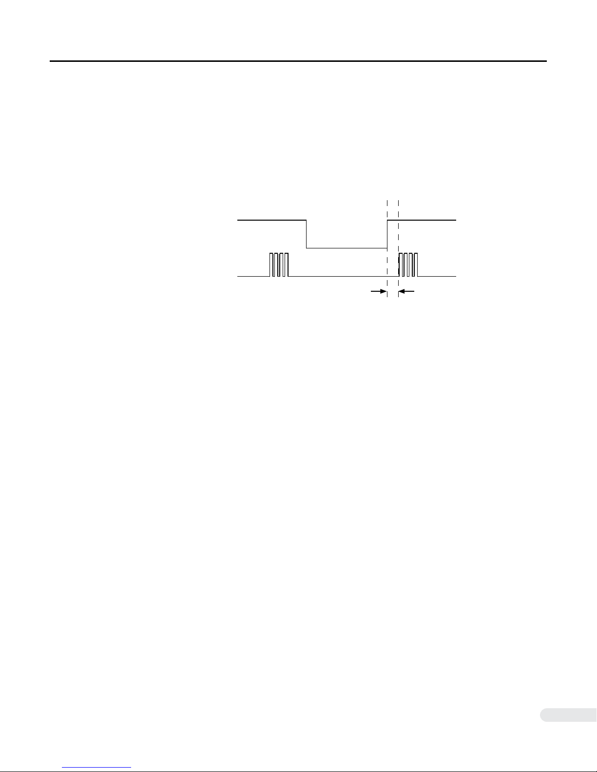
3.2 Timing Chart
■ Servo Disable / Enable Timing
When using the ENA signal to disable the servo drive to coast the servo motor, do not cycle this input
rapidly ON/OFF. If the signal is cycled too fast, the servo drive will not have enough time to initialize the
control program during Enable and can cause unwanted or dangerous results. Ensure that in the control
program, the below timing is satisfied. Once Disabled, do not Enable the servo drive during motor coast or
any time motor shaft is rotating, make sure motor shaft is completely stopped before Enable.
ON
ENA
Command Reference Input
Pulse / Analog
OFF
HIGH
LOW
Servo Enabled
Servo Disabled
20ms
DYN2MS-01E-0814A1
22
Page 23
3.3 DMMDrv Software Communication
!
♦ PC Running Requirements
Win98/XP/2000/Vista/7
250Mhz CPU
64MB RAM
250MB Hard Disk Space
The servo drive should be powered up with the servo motor encoder feedback and motor power cables
connected. The servo motor shaft will be servo-locked when powered ON. Connect the RS232 tuning
cable from port JP2 to host PC.
♦ DMMDRV Start Up
1 ) Open the DMMDRV.exe executable
2 ) Select “COMSET“ --> “COM PORT“
3 ) Change the port number to the servo drive connected RS232 port, then select “OK”
4 ) Select “SERVO SETTING”
5 ) Select DYN2 -DRIVER
6 ) Press Read on the Setting driver parameters and mode dialogue box. After approximately 1~2
seconds, the on-screen parameters will change according to the current internal parameter settings of the
connected servo drive. Ensure that the Driver Status indicates ServoOnPos to indicate that the drive has
closed the position loop with the motor and is fully operational.
WARNING
● During Test movement procedures, the servo motor can rotate very quickly in either direction. Ensure that the servo motor is free to rotate and no objects are attached to or is near
the motor shaft. Secure the motor by its ange.
♦ Test Movements
1 ) Select “RS232” under the command input mode option, then click “SAVE ALL“ to
save this setting.
2 ) Under the Test Motions menu, the user can select one of 4 test motions to JOG, STEP, SINE
or TRIM the servo motor. Only one test motion prole can be run at a time, use the radio buttons below
each section to select the movement prole.
DYN2MS-01E-0814A1
23
Page 24
4 OPERATION
4.1 Position Servo Mode
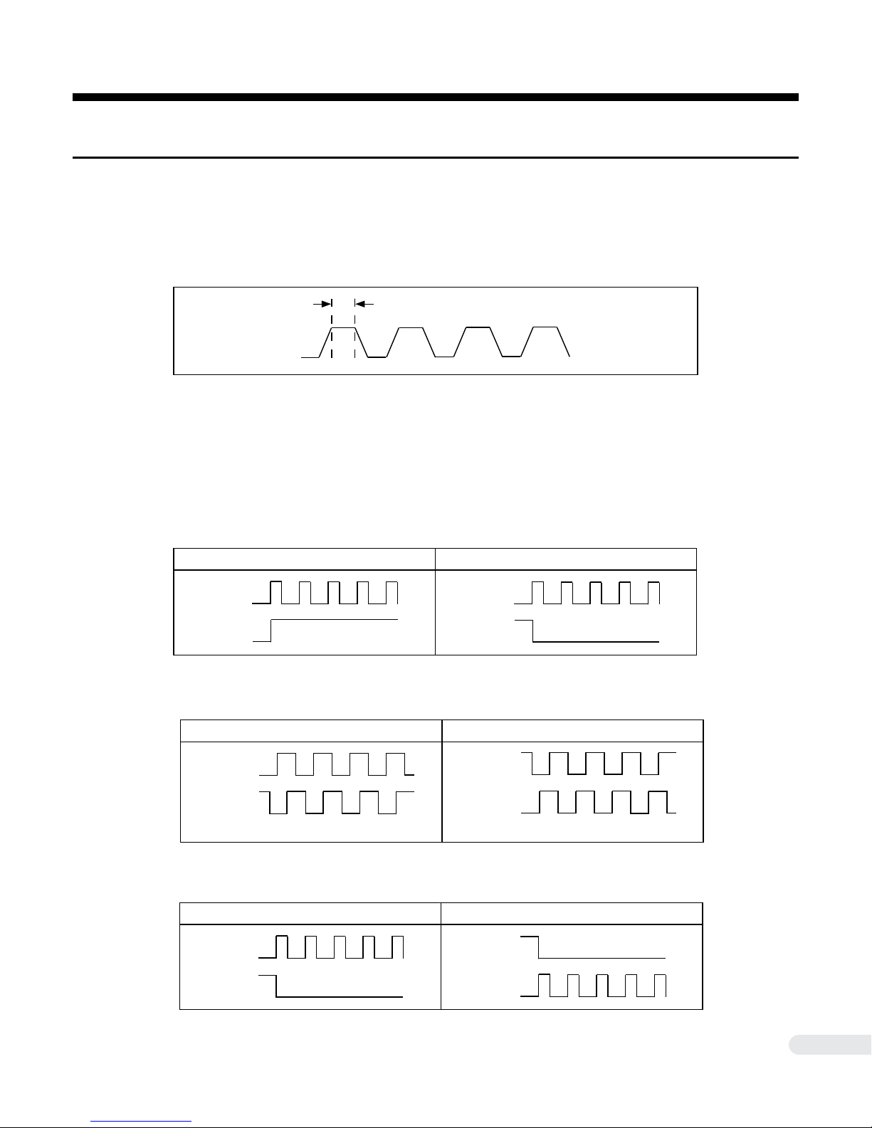
█ Pulse Specications
Voltage: +5VDC ± %10 (Contact DMM if higher level such as 12/24VDC is required)
Max pulse frequency: 500kHz
Minimum pulse width: 800us
█ Reference Pulse Format
The DYN2 servo drive accepts FORWARD reference as CLOCKWISE motor shaft rotation as viewed from
motor shaft side.
>800us
♦ Pulse + Direction
Forward Reference Reverse Reference
PUL+
JP3-6
DIR+
JP3-4
PUL+
JP3-6
DIR+
JP3-4
♦ A/B phase quadrature with 90° phase differential
Forward Reference Reverse Reference
A+
JP3-6
B+
JP3-4
A Leads B B Leads A
A+
JP3-6
B+
JP3-4
♦ CW + CCW
Forward Reference Reverse Reference
CW+
JP3-6
CW+
JP3-6
CCW+
JP3-4
DYN2MS-01E-0814A1
CCW+
JP3-4
24
Page 25
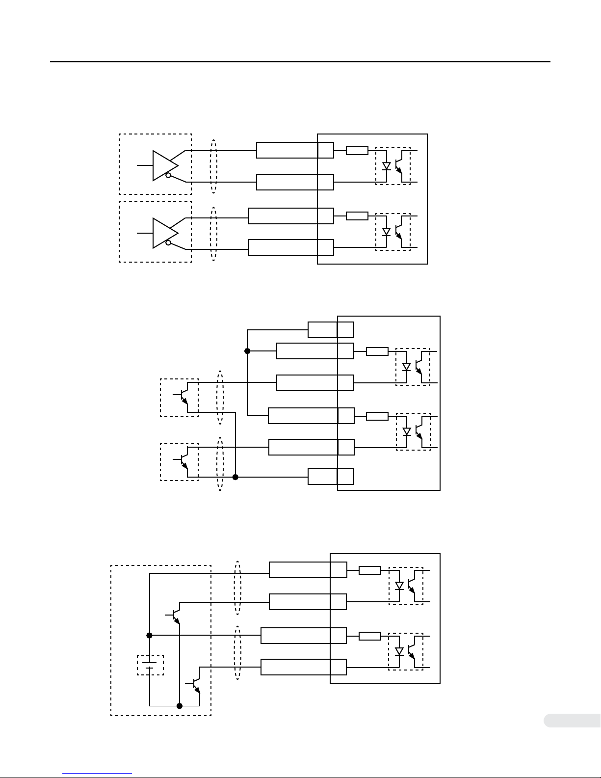
█ Connection Example
♦ Line Drive Output
PUL+, A+, CW+
4.1 Position Servo Mode
270Ω
6
PUL-, A-, CW-
DIR+, B+, CCW+
DIR-, B-, CCW-
5
4
3
♦ Open Collector Output - Internal Power Supply
PUL+, A+, CW+
PUL-, A-, CW-
DIR+, B+, CCW+
DIR-, B-, CCW-
270Ω
12+5VDC
270Ω
6
5
270Ω
4
3
♦ Open Collector Output - External Power Supply
+5VDC
DYN2MS-01E-0814A1
PUL+, A+, CW+
PUL-, A-, CW-
DIR+, B+, CCW+
DIR-, B-, CCW-
1GND
270Ω
6
5
270Ω
4
3
25
Page 26

4.1 Position Servo Mode
█ Electronic Gearing ( GEAR_NUM Parameter )
Gear number is set from 500 to 16,384, default value is 4,096. Gear number provides an electrical gear
ratio: 4096 / Gear_Num, from 0.25 ~ 8.192. For example, if Gear number = 4,096, the 16,384 input counts
from pulse will turn motor exactly one revolution. If Gear number = 500, 2,000 pulses will turn motor one
revolution.
For analog input in position servo mode, the analog input is from 0~10VDC range, by using the Gear Number, 0~10VDC analog input can turn motor from 0~90*4,096/Gear number (degrees). The gear number
has the same effect on the serial Point to Point movement or RS232 command input mode. Gear number
parameter is only effective for position servo mode.
█ Servo In Position Output Specications ( ONPOS )
On position range is a value used for determining whether the motor have reached the commanded posi-
tion or not. That on position range is selectable according to customer’s requirement. Suppose the Pset is
the commanded position, and Pmotor is the real motor position, if
|Pset - Pmotor|<=OnRange
it is said motor is ON the commanded position, otherwise not. That OnRange is set from 1~127. The real
position on range is: OnRange * 360(deg)/16,384. Set mouse curser into the OnPosition edit box, input
the desired on position value, then click the save button, On position value will be sent to the Drive with
all other parameters. The ONPOS output (JP3-9) will be HIGH if motor in position and LOW if motor off
position.
█ Servo Position Error Accumulation
The servo drive’s internal position error decides the status of the On Position signal and the Lost Phase
servo drive alarm.
The On Position signal is triggered (LOW) when the servo position error is within the OnPosRange set in
the DMMDRV program. The Lost Phase alarm is triggered when the servo motor is physically 90° or more
out of position for ~2 seconds.
The servo position error is cleared when the drive is disabled using the ENA input and does not accumulate when the drive is disabled.
DYN2MS-01E-0814A1
26
Page 27
4.2 Speed Servo Mode
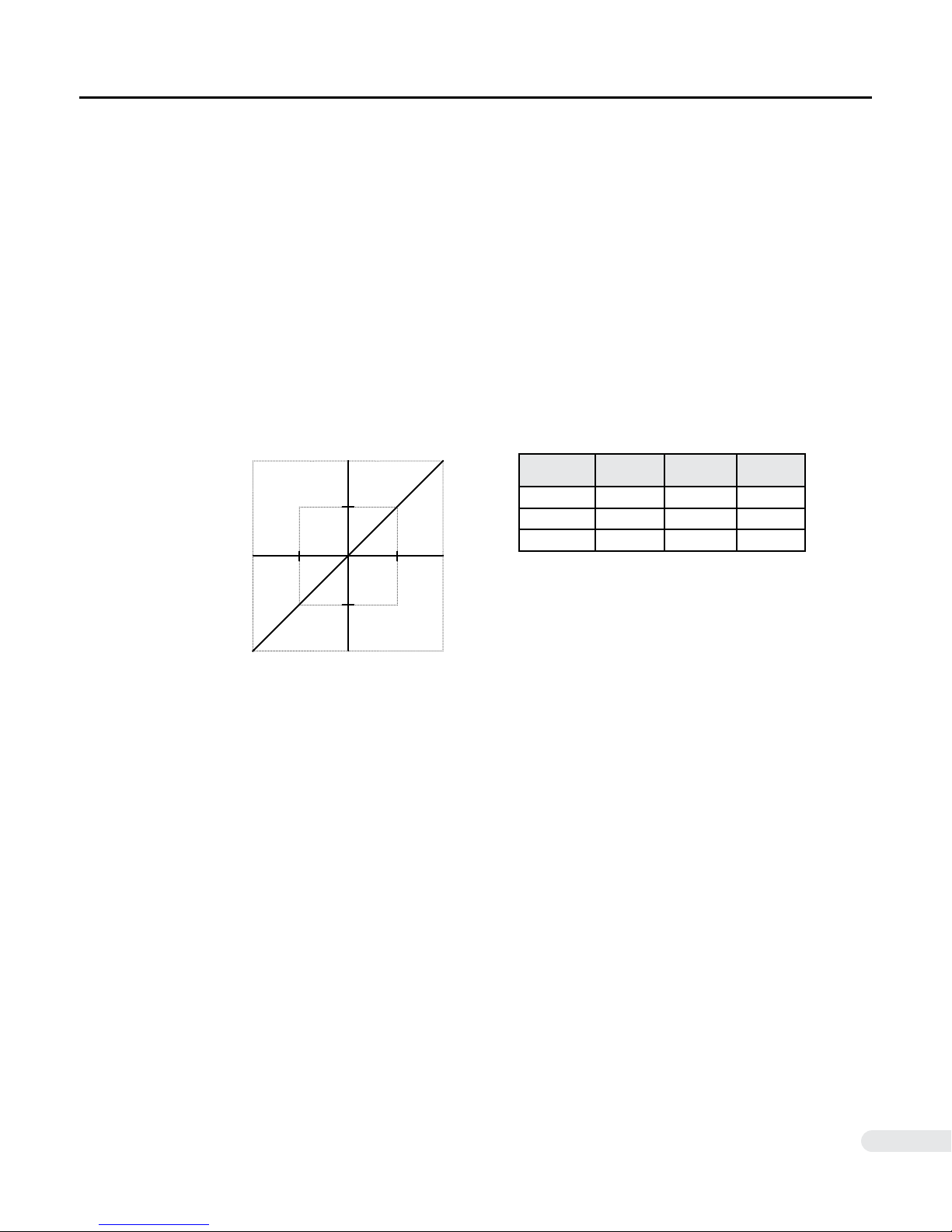
In speed servo mode, the DYN2 servo drive takes command from an external ±10VDC analog reference
voltage from the host controller to drive a linear proportional motor speed.
In speed servo mode, the torque output depends on the load on the servo motor and determined by the
motor feedback. Design the system so it can withstand the peak torque of the motor in use.
█ Control Reference
The DYN2 servo drive accepts FORWARD reference as CLOCKWISE motor shaft rotation as viewed from
motor shaft side. Positive reference voltage rotates the servo motor in the FORWARD (CLOCKWISE)
direction and negative reference voltage rotates the servo motor in the REVERSE (COUNTER CLOCKWISE) direction.
6,000rpm
3,000rpm
Motor Speed
Reference Voltage
+10V-10V -5V +5V
Reference
Voltage
+10V 6,000rpm FWD CW
+5V 3,000rpm FWD CW
-3V 1,800rpm REV CCW
Motor
Speed
Reference
Direction
Motor
Direction
DYN2MS-01E-0814A1
27
Page 28
4.2 Speed Servo Mode
█ Acceleration / Deceleration Soft Start
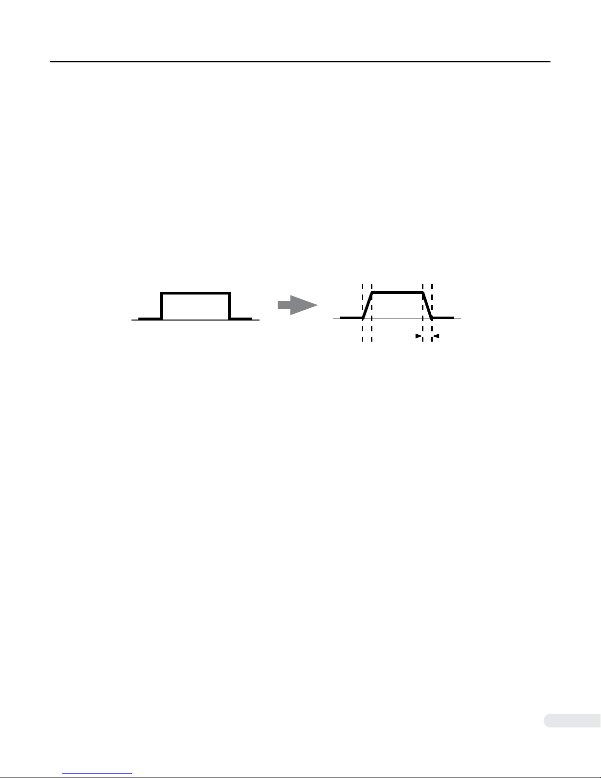
In Speed Servo Mode, the Max Acceleration parameter in the servo drive can be used to soft start/stop the
servo motor. Since the speed command is sent as a rough step reference, it is often desirable to smooth
out the servo motor’s movement dynamics. Without soft start, the servo motor can accelerate/decelerate
too instantaneously. Soft start creates a smooth s-curve motion.
The relation to physical acceleration / deceleration time is measured as the rise time from 10% of the target speed to 90% of the target speed.
2
Rise from 10% to 90% time = 59.98/(Max Acceleration)
Physical acceleration time = 1.2 * 59.98/(Max Acceleration)
seconds
2
seconds
Rough Motion
Smooth Motion!
█ Torque Filter Constant
TrqCons is a first order low-pass filter used to smooth torque delivery in speed servo mode
which improves stability and accuracy of servo motor speed. The bigger value means wider
frequency range of that filter. That filter can be expressed as:
a / ( S + a), here a = 26*TrqCons ; if TrqCons = 100, then a = 2600.
The filter is used to make the torque sent to the servo torque loop more smooth especially
for the heavier load when bigger SpeedGain setting is used. If a very quick response servo
with small load is desirable, the bigger value or even the value 127 should be used to ensure stability and fast dynamic follow.
Max Acceleration
The Torque Filter Constant parameter should only be used in speed servo mode. Leave this
parameter at “127” in position servo mode.
DYN2MS-01E-0814A1
28
Page 29
4.3 Torque Servo Mode
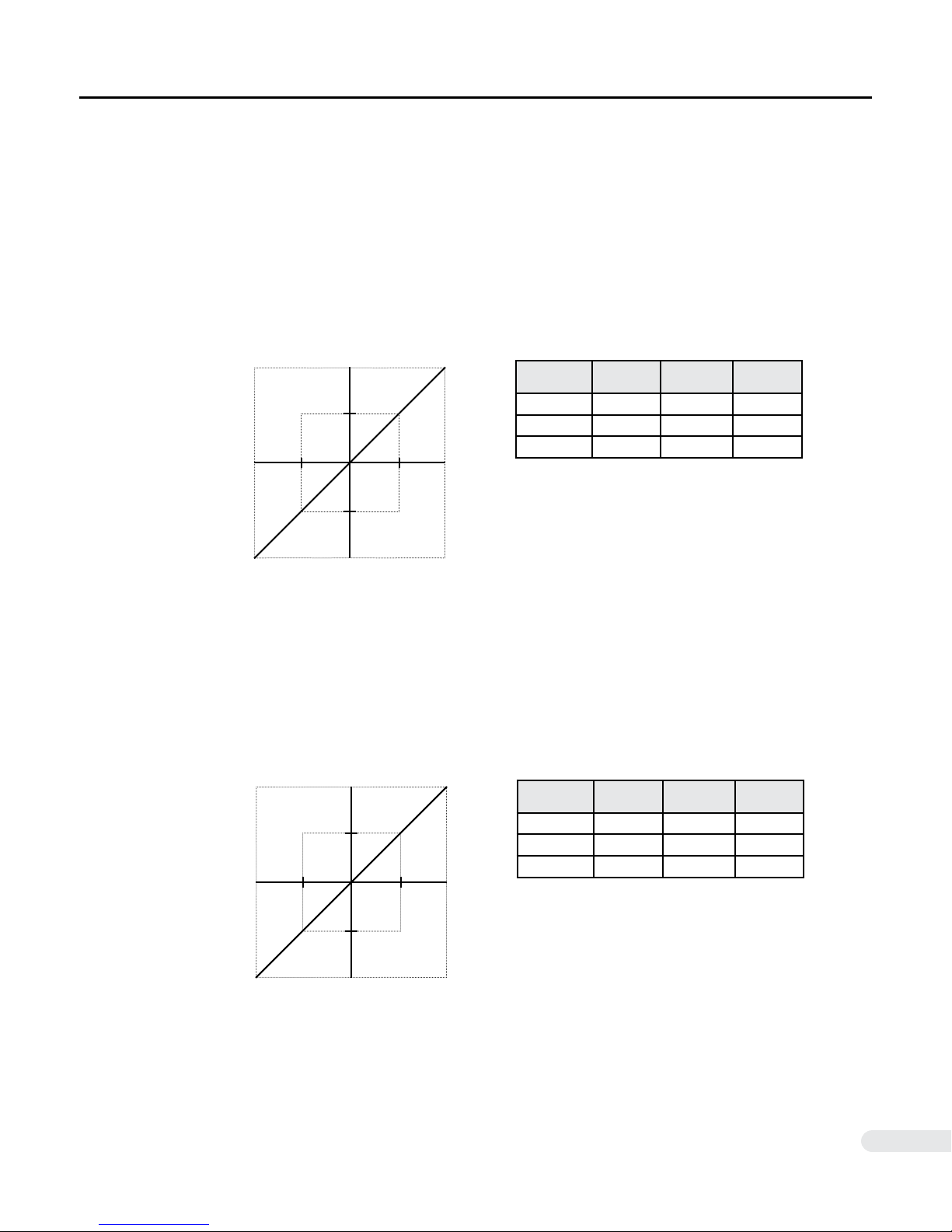
In torque servo mode, the DYN2 servo drive takes command from an external ±10VDC analog reference
voltage from the host controller to drive a linear proportional output current.
█ Control Reference - [ 1 ] Capacity Model: DYN2-T1
The DYN2 servo drive accepts FORWARD reference as CLOCKWISE motor shaft rotation as viewed from
motor shaft side. Positive reference voltage rotates the servo motor in the FORWARD (CLOCKWISE)
direction and negative reference voltage rotates the servo motor in the REVERSE (COUNTER CLOCKWISE) direction.
10.0A
5.0A
Reference Voltage
+10V-10V -5V +5V
Current Output
Reference
Voltage
+10V 10.0A FWD CW
+5V 5.0A FWD CW
-3V 3.0A REV CCW
Output
Current
Reference
Direction
Motor
Direction
█ Control Reference - [ L ] Capacity Model: DYN2-TL
The DYN2 servo drive accepts FORWARD reference as CLOCKWISE motor shaft rotation as viewed from
motor shaft side. Positive reference voltage rotates the servo motor in the FORWARD (CLOCKWISE)
direction and negative reference voltage rotates the servo motor in the REVERSE (COUNTER CLOCKWISE) direction.
20.0A
10.0A
Reference Voltage
+10V-10V -5V +5V
Reference
Voltage
+10V 20.0A FWD CW
+5V 10.0A FWD CW
-3V 6.0A REV CCW
Output
Current
Reference
Direction
Motor
Direction
DYN2MS-01E-0814A1
Current Output
29
Page 30

4.4 RS232 Command Input Mode
The RS232 port is always active after power on for DYN-series servo drive, that active RS232 port could
be used for reading and setting Drive parameters and status, also could be used for sending point to point
position command if the RS232 mode is selected for position command input.
If the position command input mode is selected as Pulse mode or Analog mode, the RS232 port is still
active as mentioned above but it only can be used for reading and setting Drive parameters. The RS232
port could be easily accessed by using the GUI interface DMMDRV.exe after the connection between PC
and the Drive’s RS232 port. This is the easiest way to tune up the servo and make some test movements.
The RS232 port could be accessed by other microcontroller, or DSP if sending and reading data by using
DYN Drive’s RS232 protocol.
The PC or DSP is working as Master and the servo drive is always as slave. Several servo drives could
be linked for a serial network integrated multi-axis control.
See (Appendix A) for DYN2 servo drive RS232 protocol definitions.
4.5 Absolute Zero Position Index Output (ZRI)
The ZRI signal is output once per motor revolution to facilitate servo homing and indexing functions. ZRI
pulse can also be used to count motor revolutions or monitor servo motor speed. Accuracy of each pulse
is maintained by 14/16-bit absolute encoder. The mechanical output position of ZRI may vary between
each servo motor. It can also be used to compensate for mechanical or ball screw backlash. A calibration
procedure is necessary to set the absolute ZRI position in the controller.
The user should calibrate the position of the ZRI output with respect to the target mechanical position. The
falling edge of the ZRI output (JP3 Pin.10) should be used as the trigger. Pulse width and rising edge of
ZRI should not be used as trigger.
ZRI
JP3 Pin.10
ZRI Falling Edge Trigger
+5V
0
DYN2MS-01E-0814A1
30
Page 31
5 PARAMETERS AND TUNING
5.1 Parameters Outline
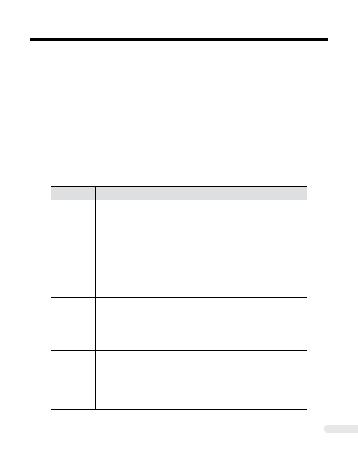
The following parameters are adjustable by connection through RS232 or USB interface from the servo
drive to the PC. No matter the command mode, the JP2 RS232 port is always active for parameter setting
and drive configuration.
The Drive configuration and servo cons are stored in the EEPROM of servo drive when the save button is
pushed or parameters setting is issued through the serial communication.
The guaranteed write cycle for the EEPROM is 1 million times. Do not use serial communication to constantly change the drive parameters as this will decrease servo drive life span. Major parameter change
and setting should only be done during initial testing and tuning. Actual drive operation should not require
constant parameter changes unless changing servo control modes on the fly through RS232.
Parameter Name Setting Range Details
Main Gain [ 1 : 127 ]
Speed Gain [ 1 : 127 ]
Integration Gain [ 1 : 127 ]
Torque Constant [ 1 : 127 ]
The main gain for the servo loop, usually to be increased
as the motor load increases. The bigger value of MainGain
means wider frequency range of servo loop relatively.
The speed gain for the servo loop, usually to be increased
as the motor load increases. The bigger value of speed
Gain means narrower frequency range of servo loop
relatively. Physically, heavier loads or higher inertia loads
should have lower dynamic ability, so the servo loop frequency range should be more narrow by using bigger value
of Speed Gain. If the Speed Gain is too high, there will
be some loud noise because the torque command will be
too coarse, not smooth, the smaller Torque Constant (see
TrqCons) could be used to attenuate this noise.
There is an integrator in the servo loop to ensure the error
between position command and real position be zero
during the steady state. Also that integrator will let servo
have more ability to attenuate the outside disturbance
torque. The bigger value of IntGain, the more ability of the
servo to attenuate the outside disturbance torque. Integration Gain should be decreased for heavier loads or higher
inertia loads.
TrqCons is a rst order lter constant, the bigger value
means wider frequency range of that lter. That lter can
be expressed as : a / ( S + a), here a = 26*TrqCons, if
TrqCons = 100, then a = 2600. That lter is used to make
the torque sent to torque loop more smooth, especially for
heavier loads when bigger SpeedGain is used. If a very
quick response servo with small load is desirable, a bigger
value or even the value 127 should be used to ensure the
stability and dynamic performance.
Applicable Servo
Mode
Position
Speed
Torque
RS232
Position
Speed
Torque
RS232
Position
Speed
Torque
RS232
Speed
Torque
RS232
DYN2MS-01E-0814A1
31
Page 32

5.1 Parameters Outline
Parameter Name Setting Range Details
Determine the S-curve acceleration when using RS232
Max Acceleration [ 1 : 127 ]
Max Speed [ 1 : 127 ]
Driver ID [ 1 : 126 ]
On Position Range [ 1 : 127 ]
mode to make point to point motion linear/circular. Also
controls the response time of the rst order low pass lter
in speed and torque servo control (soft start).
Determine the S-curve max speed when using RS232
mode to make point to point motion linear/circular.
Every drive has a unique ID number, which can be
assigned or read out by using ServoSetting dialog box.
Applicable when RS485net box not checked and there is
only one Drive connected through the RS232 port.
The default ID number for every Drive is 0. That ID number can be used for the network connection of RS485 or
for drive unit identication purposes. When RS485net box
is checked and there are more than one Drive connected
to the RS485/232 network, only the setting for the Drive
with the indicated ID number in the ServoSetting dialog
box can be read out or saved.
On position range is a value used for determining whether
the motor have reached the command position or not.
That on position range is selectable according to user’s
requirement. Suppose the Pset is the commanded position, and Pmotor is the real motor position, if
it is said motor is on the commanded position, otherwise
not.
|Pset - Pmotor|<=OnRange
Applicable Servo
Mode
RS232
Speed
Torque
RS232
Position
Speed
Torque
RS232/485
Position
Speed
Torque
RS232
Gear Num [ 500 : 16,384 ]
The amount of motor travel with reference to the number
of input pulses is set using the parameter Gear_Num.
The number of reference pulse needed for one complete
motor revolution is calculated as,
One motor revolution = 4xGEAR_NUM
For example, if Gear_Num is set to 4096, then 16,384
pulses are needed from the host controller for the motor to
make one complete revolution.
Position
RS232
DYN2MS-01E-0814A1
32
Page 33
5.2 Servo Drive Gain Tuning
The DYN2 servo drive features simple 3 parameter Gain tuning to achieve optimized smooth performance.
The user should adjust the servo gain parameters Main Gain, Speed Gain and Integration Gain until they
achieve target response qualities. These parameters are all adjustable using the DMMDRV program.
The overall method of Gain tuning follows as load mass or load inertia increase, the Main Gain and Speed
Gain parameters should be increased. If these are set too high, the servo may be over-tuned and start
vibrating or become noisy. The parameters should be increased/decreased until the motor smoothly follows command without vibration, noise or oscillations. The user can then fine tune the parameters to make
the motor “harder“ (faster response, more rigid motion) or “softer“ (slower response, smoother motion).
The servo motor should be coupled to the final machine before tuning. Make sure during tuning, the motor
is running the load and speed of the final machine or design. The user should use a trial and error method
to achieve the desired servo response.
In Speed servo mode, the Torque Filter Constant parameter can be adjusted to further smooth the torque
delivery and improve motor speed accuracy.
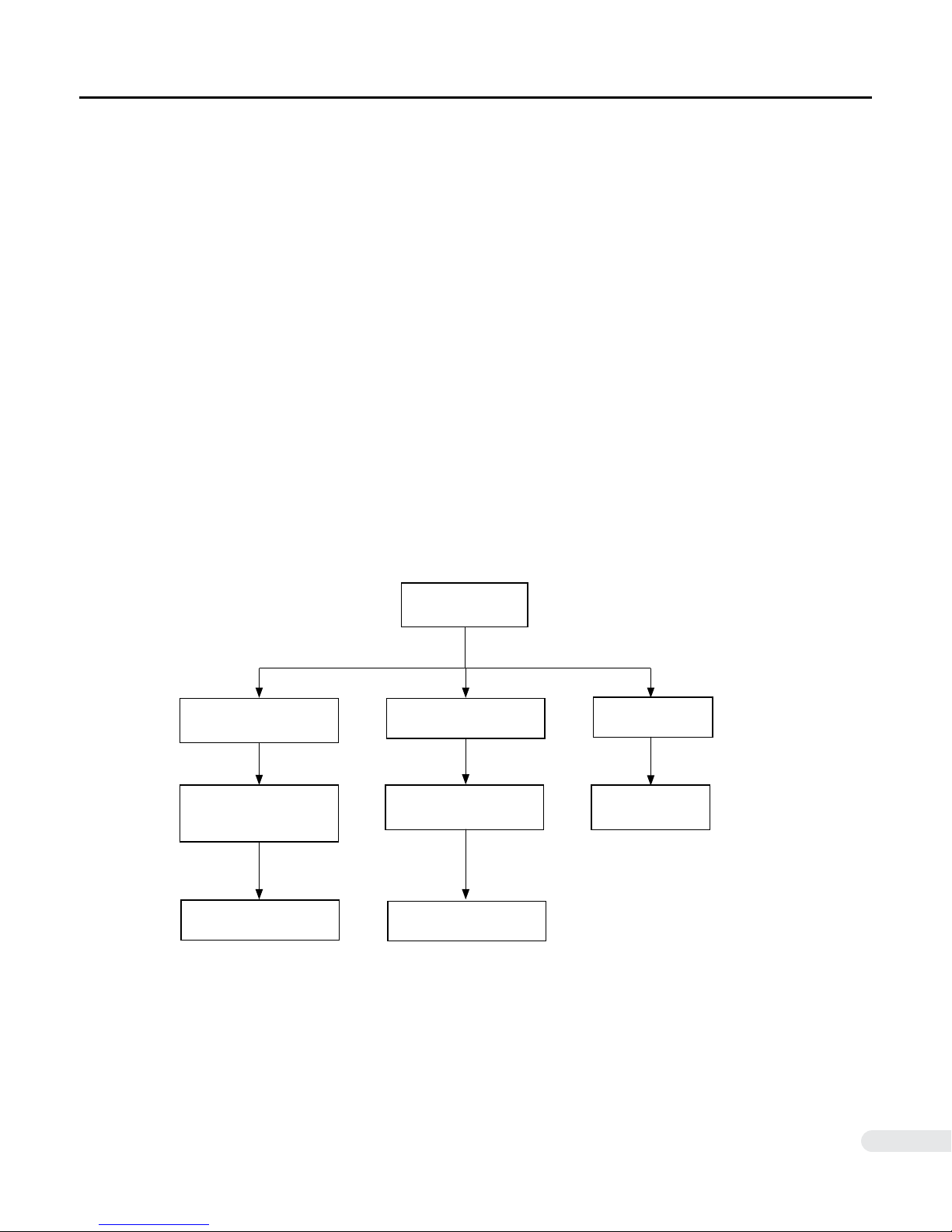
♦ Gain Tuning Procedure Flow
Position Overshooting or
Oscillation.
Increase Main Gain,
increase Speed Gain until
overshooting supressed
If still unstable
Decrease Integration Gain
Tuning Begin
Run Servo Motor
Motor Vibration/Noise
Decrease Main Gain,
decrease Speed Gain
If still unstable
Decrease Integration Gain
Speed Servo Mode
Unstable/Vibration
Decrease
Torque Filter Constant
DYN2MS-01E-0814A1
33
Page 34

5.2 Servo Drive Gain Tuning
█ Sample Load Type Tunings
♦ Ball Screw
Ball screw systems are mechanically very rigid and stiff. If high resolution pitch (e.g. 5mm
or 10mm) the default setting could even be used. The servo drive can be easily tuned
using Main Gain, Speed Gain, and Integration Gain. Increase Main Gain, Speed Gain and
Integration Gain relative to load mass until target response achieved. Decrease Integration
Gain if load inertia is big and system oscillates.
♦ Direct Mechanical Drive (Rigid systems, Robots)
Depending on load mass and inertia, increase Main Gain, Speed Gain and Integration Gain
until target response achieved. Decrease Integration Gain if load inertia is big and system
oscillates. In speed/torque servo mode, if relative load inertia is very high, the high Speed
Gain might increase motor noise, then decrease the Torque Filter Constant to attenuate
torque loop noise.
♦ Belt Drive / Pulley
Belt drive or pulley systems are low mechanical rigidity with slower response. Main Gain
and Speed Gain should be increased with higher load mass and relative load inertia. Integration Gain should be decreased to give the position loop more time ro react to the low
rigidity system.
DYN2MS-01E-0814A1
34
Page 35
6 MAINTENANCE
6.1 Alarm Specications
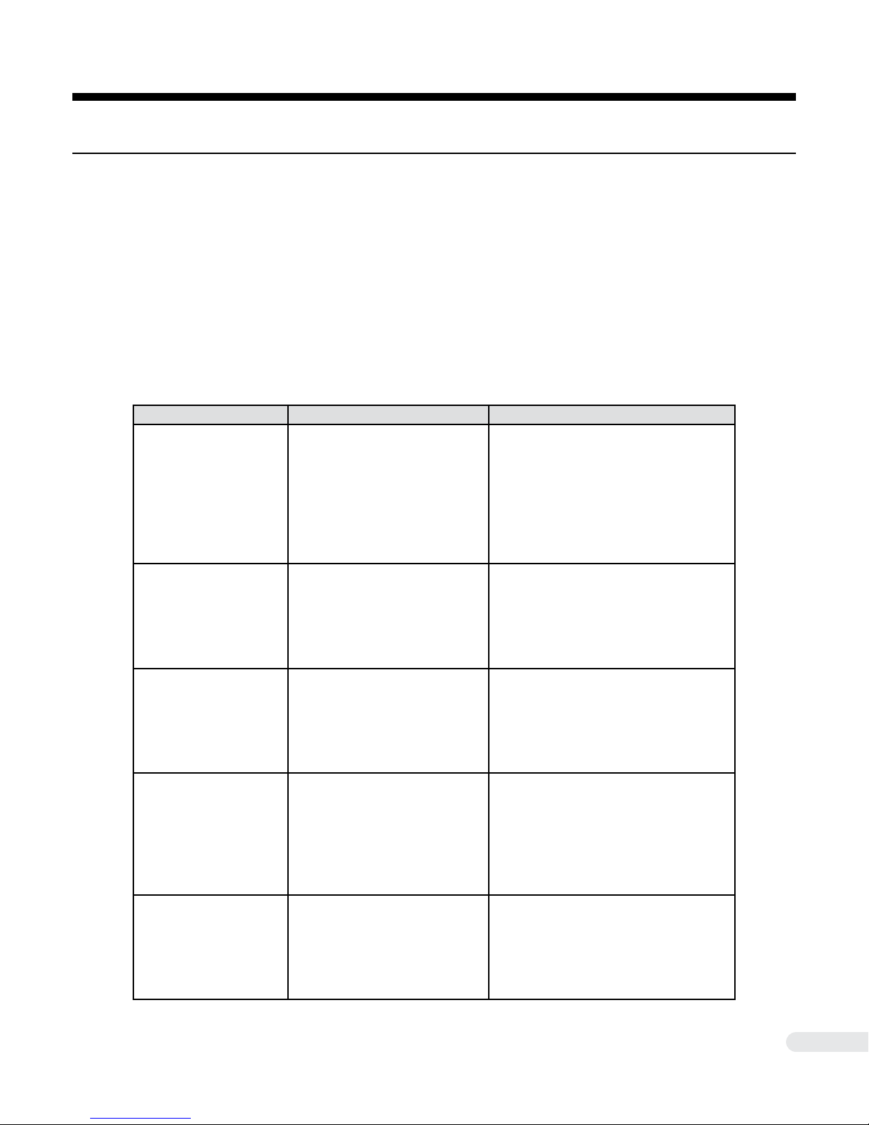
The DYN2 servo drive is protected by 5 alarms. The S1 status indicator LED will flash to indicate when an
alarm is triggered. The specific alarm status can be read using the DMMDRV program.
♦ Internal Driver Status Readout
( 1 ) Connect the PC to the servo drive JP2 port using RS232 cable
( 2 ) Press Read on the Setting driver parameters and mode main screen.
( 3 ) The Driver Status box will display the current status of the Servo Drive.
Alarm Cause Recommended Correction
Over Voltage
Over Temperature
Lost Phase
Over Power
Over Current
The internal DC bus voltage has
exceeded the allowed maximum levels. The input DC voltage is too high.
The servo drive’s protective thermal
resistor has detected an unusually
high temperature inside the drive.
The control power transistor temperature is too high.
The encoder has detected an
irresolvable position error in the motor relative to the command signal.
The servo drive has experienced an
output power exceeding the rated
value relative to the average value.
The servo motor cannot move to its
command position and there is a
backlog of current in the servo drive
to try to move the servo motor.
- Check and conrm the connections to
the servo motor.
- Check that the servo motor is driving a
mass appropriate to its size.
- Check for any mechanical irregularities
that might be preventing the motors to
move freely.
- Add an external regenerative resistor
- Check that the drive’s ventilation
openings and heat sink are not being
blocked.
- Consult the servo drive’s ambient
temperature specications and check if
the operation conditions are met.
- Check that the encoder feedback cable
is securely plugged from the servo motor
to the JP3 port of the servo drive.
- Check for any mechanical irregularities
that might be preventing the motors to
move freely.
- Check and conrm the connections to
the servo motor.
- Check that the servo motor is driving a
mass appropriate to its size.
- Check for any mechanical irregularities
that might be preventing the motors to
move freely.
- Check that the encoder feedback cable
is securely plugged from the servo motor
to the JP3 port of the servo drive.
- Check for any mechanical irregularities
that might be preventing the motors to
move freely.
DYN2MS-01E-0814A1
35
Page 36
6.1 Alarm Specications
!
♦ Alarm Motor Stop
The power to the servo motor will be stopped when an alarm is triggered. Internal servo control turns off
and servo motor shaft becomes free. Power still remains in the logic circuit for drive diagnostic and drive
status reading. All commands including pulse, analog and RS232 will be ignored and will not accumulate
the internal position error.
♦ Alarm Reset
Once servo drive triggers an alarm, the user should use the DMMDRV program to read out the alarm
condition then inspect the machine, load or operation for cause to the alarm. The problem should be fixed
before re-setting the servo drive and running again. The servo drive main power should be cycled to fully
re-set and clear the servo alarm status.
WARNING
● If the servo motor is coupled to a vertical axis that can drop due to gravity when the shaft
becomes free, take measure to prevent injury or damage when the drive alarm is triggered.
A motor with brake option may be necessary to stop vertical axis, or any axis acted on by an
external force, from dropping or crashing.
6.2 - Drive Maintenance
Do not perform maintenance on the servo drive unless instructed to do so by DMM. The servo drive cover
or chassis should never be removed as high voltage components can cause electric short, shock or other
damage upon contact. Disassembly, repairs or any other physical modification to the servo drive is not
permitted unless approved by DMM.
♦ Regular Inspection
Inspect the servo drive regularly for:
● Dirt, dust or oil on the servo drive - make sure the servo drive cooling duct and heat
sink are free from debris
● Environment - ambient temperature, humidity and vibration according to servo drive
specification
● Loose screws
● Physical damage to servo drive or internal components
DYN2MS-01E-0814A1
36
Page 37
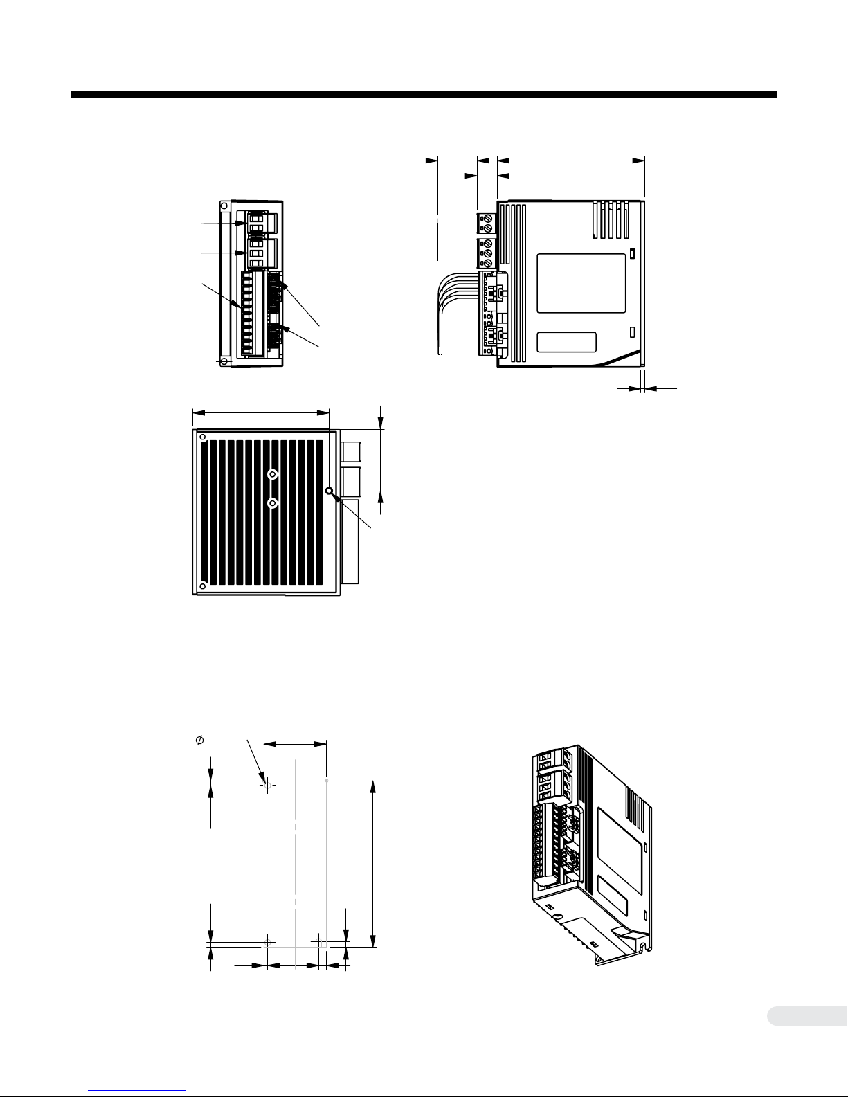
APPENDIX A - SERVO DRIVE DIMENSIONS
( Name Plate 1 )
( Name Plate 2 )
75
10
2
JP4
JP2
( Name Plate 1 )
( Name Plate 2 )
75
10
2
20
31
70
Chassis Ground
Terminal
♦ Exterior Dimensions
JP1
JP5
JP3
70
JP2
JP4
31
Chassis Ground
Terminal
20
75
10
( Name Plate 1 )
( Name Plate 2 )
2
♦ Mounting Footprint
3 x
3 Mount
2.5 2.5
2
32
4
85
3
DYN2MS-01E-0814A1
37
Page 38

APPENDIX B - RS232 Protocol Denition
*NOT INCLUDED IN MANUAL REVISION. A1
DYN2MS-01E-0814A1
38
Page 39

APPENDIX C - Operation Examples
█ Position Servo Mode - Ball Screw
1. Connect encoder feedback and motor power cable from servo drive to servo motor.
2. Connect RS232 tuning cable from servo drive JP2 to controller PC.
3. Power ON servo drive.
4. Open Windows Device Manager - Locate COM Port Number of RS232 tuning cable.
5. Open DMMDRV program.
6. Select COMSET --> COM PORT. Press “Change Port“ until RS232 tuning cable COM
port number selected. Press “ok“.
7. Select ServoSetting --> DYN2-DRIVER. Setting drive parameters and mode main screen
will open.
8. Press “Read” to read out the factory default or current setting of the servo drive. At any
time, pressing “Save All“ will save the parameters into the servo drive.
9. Under Servo Mode, select “Position Servo”.
10. Under command input mode, select “Pulse/Dir”,
“A/B Phase”, or “CW/CCW”.
11. Set GEAR_NUM parameter according to
ball screw pitch and target travel speed.
Example:
Ball screw pitch = 10mm
Reduction = 2:1
Target Speed = 15m/min
Rated Motor Speed = 3,000rpm = 50rev/s
Controller Pulse Output Frequency = 100kHz = 100,000pulse/s
3,000rpm / 2 = 1,500rpm after reduction
1,500rpm * 10mm = 15,000mm/min = 15m/min
100,000pulse/s / 50rev/s = 2,000pulse/rev
2,000pulse/rev / 4 = 500
GEAR_NUM = 500
12. Tune Gain and OnPosition Range according to machine and operation requirements.
13. Click “Save All“ when finished adjustments.
14. The servo drive is ready to accept position pulse commands.
DYN2MS-01E-0814A1
39
Page 40

Warranty and Liability
█ Warranty
Products from DMM Technology Corp. are supported by the following warranty.
● 1-year from the date of product received by customer or 14 months from the month of original
invoice.
Within the warranty period, DMM Technology Corp. will replace or repair any defective product free of
charge given that DMM Technology Corp. is responsible for the cause of the defect. This warranty does
not cover cases involving the following conditions:
● The product is used in an unsuitable or hazardous environment not outlined in this manual, resulting in damages to the product.
● The product is improperly handled resulting in physical damage to the product. Including falling,
heavy impact, vibration or shock.
● Damages resulting from transportation or shipping after the original factory delivery.
● Unauthorized alterations or modifications have been made to the product.
● Alterations have been made to the Name Plate of the product
● Damages resulting in usage of the product not specified by this manual.
● Damages to the product resulting from natural disasters.
● The product has cosmetic alterations.
● The product does not conform to the original factory manufactured standards due to unauthorized
modifications.
█ Liability
Use, operation, handling and storage of the DYN2 AC Servo Drive is solely responsible by the customer.
Any direct or indirect commercial loss, commercial profit, physical damage or mechanical damage caused
by the DYN2 AC Servo Drive is not responsible by DMM Technology Corp. The features and functionality
of the product should be used with full discretion by the customer.
Above terms are current as of August 2014
DYN2MS-01E-0814A1
40
Page 41
Product and Manual Disclaimer
█ Disclaimer
DMM Technology Corp. constantly strive to improve it’s products performance and reliability. The contents
of this manual outlines the latest features and specifications of the DYN2 AC Servo Drive and may be
changed at any time to reflect corrections, improvements or changes to the product or information in this
manual.
█ Manual Revision History
Version Manual Number Details Date
A1 DYN2MS-01E-0814A1 Release Version August 2014
█ DYN2 Servo Drive Revision History
♦ Hardware Version
Version Details Date
AH10 Release Version June 2014
♦ Software Version
Version Details Date
AH10 Release Version June 2014
DYN2MS-01E-0814A1
41
Page 42

DYN2 Series
AC Servo Drive
Type - A General-Purpose Pulse/Analog
Specication Manual
Manual Number
Revision
: DYN2MS-01E-0814A1
: A1
Electronic Version
DMM TECHNOLOGY CORP.
3125 - 21331 Gordon Way Richmond, British Columbia V6W1J9 Canada
PHONE: +1 604-370-4168
WEB: http://www.dmm-tech.com
SALES: [email protected]
INFO: [email protected]
Copyright © 2014 DMM Technology Corp.
Published In Canada
 Loading...