

Page 1
USER GUIDE
AUDIO-POD MUTE
Microphone Cough/Mute Control and
Integrated Headphone
Amplifier System
Version 1.1
DM Engineering
2174 Chandler St.
Camarillo, CA 91345-4611
805-987-7881 800-249-0487
www.DMEngineering.com
Page 2

2
Overview:
The “Audio-Pod Mute” is a Microphone Mute/Cough button control system with an
integrated headphone amplifier and switched microphone phantom power, which is
ideal for remote broadcasts, podcasts, and talk studio applications. The Microphone
in/out employs XLR type connectors.
An Audio-Pod system consists of from one to four Audio-Pod modules and a Power
Supply. One Power Supply will supply power for up to four Audio-Pod modules, and
the modules may include any of the available models and variety of options. A 10
foot Power Supply cable is supplied with each module.
Optional permanent table top tilt mounting brackets and recessed flush mounting
bezels for permanent flush mount solutions for the Audio-Pod modules are also
available.
The Microphone mute/cough circuit includes the following features:
Large LED differentially lighted Mute/Cough button is a long life reed
type silent push button
Microphone XLR in and XLR out connectors as well as Eurostyle screw
terminal termination of Mic out connection for permanent installations
Precision metal film resistors used throughout audio chain for low
noise and stability
Phantom power supplied with a rear panel switch and LED indicator
The integrated headphone amplifier section includes the following features:
Voltage Controlled Amplifier (VCA) circuitry employed (no “dirty” pots)
Power Op-Amp headphone output providing both the power and P-P
voltage required to drive headsets ranging from 8 to 600 ohms
Rear panel output phase switch (0-180O) to address bone conduction
cancellation issues sometimes experienced by users
ESD protected front panel 3.5mm and ¼” stereo headphone output
jacks
Rear panel maximum headphone gain set control to restrict the
maximum headset output to prevent possible hearing damage and
liability issue avoidance
Single ended L&R inputs via a rear panel 3.5mm jack for quick connect
applications and on Eurostyle screw terminal connectors for more
permanent connections
Precision metal film resistors used throughout the audio chain for low
noise and stability
Headphone input isolated for up to 50VDC per channel
Installation:
1. Mount the Power Supply within 10’ of the Audio-Pod location. Mounting may
be table top or under the desk mounting using the supplied mounting screws
and “keyhole” slots located on the bottom of the power supply cabinet.
(3” center to center mounting holes) Orientation may be in two different axes
depending upon user preference.
2. The Audio-Pod modules are normally desk top mounted using the supplied
rubber feet. If the optional table top or flush mounting brackets are used, refer
to the installation instructions that accompany them
Page 3
3
3. Connect the Power Supply to the Audio-Pod using the supplied 10ft. 8 pin MiniDin cables. The orientation of the connector has the flat side facing the top of
the enclosures. IMPORTANT: Assure that the Mini-Din connectors are fully
engaged with the sockets. Insert, wiggle and press firmly! Failure to
completely insert the power cables will result in hum or non-operation of the
Audio-Pod module.
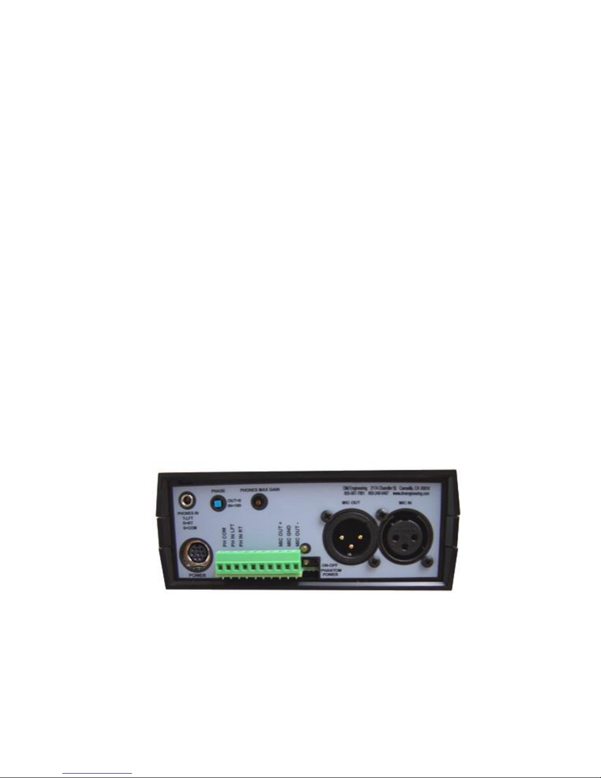
4. Connect the microphone XLR in and out connectors to the respective
receptacles. A more permanent wire output connection, balanced or
unbalanced, may be made using the Eurostyle screw terminal connector “MIC
OUT +”, “MIC GND”, and “MIC OUT –“ terminals.
5. Connect the single ended headphone inputs to the 3.5mm “PHONES IN”
connector, (lft=tip, r=ring, com=sleeve) or the “PH IN LFT”, “PH IN RT”, and
“PH COM” (headphone common or ground) terminals.
6. Connect the AC power cord to a 115VAC outlet. The LED indicator on the
power supply should light as well as the “Mute/Cough” button on the Audio Pod.
Headphone Section:
1. Select the type of headset desired and insert the jack into the appropriate
“Phones” receptacle. The rear panel “PHONES MAX GAIN SET” is factory preset to about mid range and may be adjusted to the users desired maximum
level.
2. To reset the maximum headset level, have the headset audio input source
active, slowly adjust the front panel “GAIN” control to maximum while using the
an adjusting tool to set the rear panel “PHONES MAX GAIN SET” to the
maximum level that you feel is safe for the user. This feature is included to
protect the user from possible damaging volume levels to their hearing which
may lead to possible litigation in the future.
WARNING: Listening to earphones too loudly may cause hearing loss. To
prevent hearing loss, adjust the volume to comfortable levels and avoid
prolonged use.
Operation:
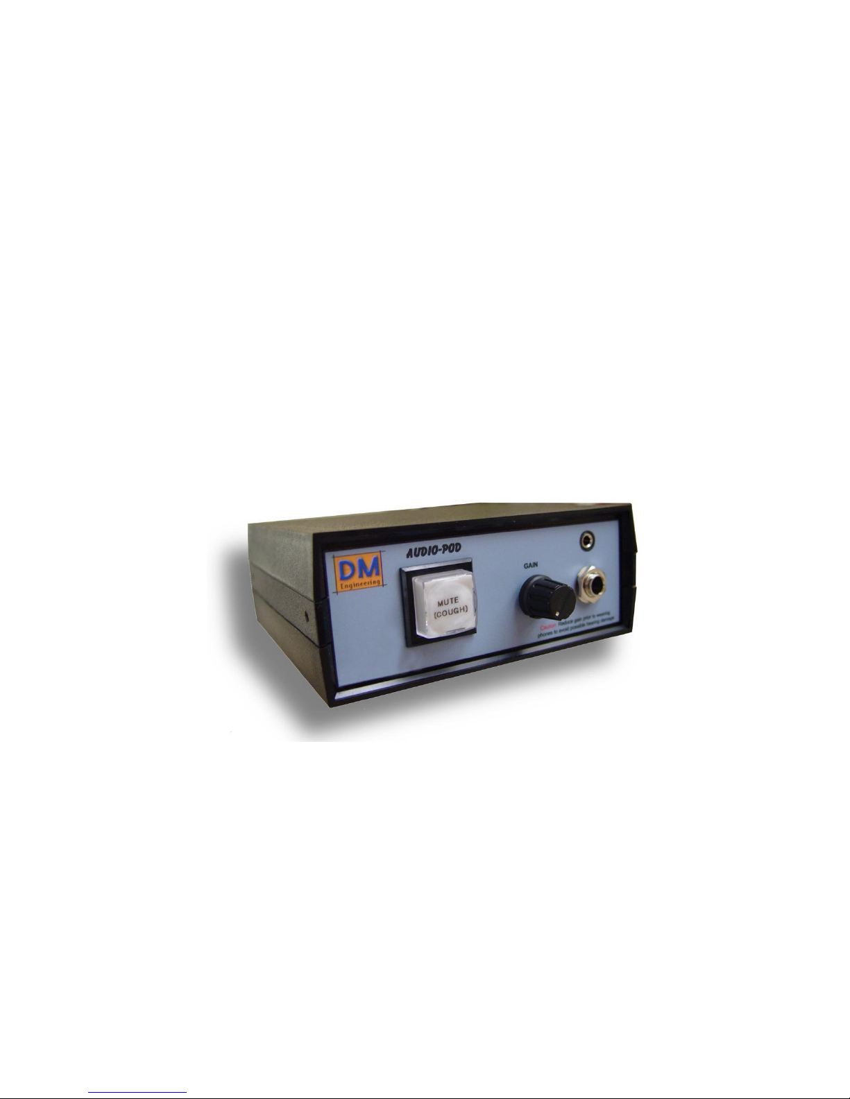
The Audio-Pod front panel control functions are as follows:
MUTE/COUGH: Mutes the microphone function.
GAIN: Sets the headset gain and is adjusted by the user to a comfortable volume
level.
PHONE JACKS: Both ¼” and 3.5mm stereo headphone jacks are supplied. The
jacks are connected in parallel and employ ESD protection circuitry for protection
from static build-up on the earphone plug that is being connected.
Page 4

4
The Audio-Pod rear panel headset control adjustments are as follows:
PHASE: Depressed for 180° phase shift in the headphone output to correct for bone
conduction issues that may arise, and left in the outermost position for 0° phase
shift.
PHONES MAX GAIN SET: Factory pre-set to approximately mid range and may be
adjusted to the users desired maximum level. (Refer to headphone section setup
instructions above.)
Note: It is imperative that the “PHASE” switch be depressed prior to opening the
Audio-Pod enclosure or damage to the switch will result. This switch damage is not
covered by the warranty provisions.
Warranty Information:
The DM Engineering Audio-Pod system is warranted for a period of one year from
the date of purchase. This warranty covers materials and workmanship only. Any
misapplication, physical or electrical damage from outside sources or by the customer is
not covered. For factory warranty repairs, the customer must pay shipping costs to the
factory, and DME will pay standard ground transportation shipping costs to return the
warranted equipment to the customer. Any priority shipping costs are to be the
responsibility of the customer as ground service is standard. Please contact the factory
for an RMA number prior to any returns. Items returned without an RMA may be
returned to the customer unopened.
Technical Support:
If you have questions, experience difficulties with the product or require further
information please contact DME at: 805-987-7881, toll free 800-249-0487, or E-mail
technical support at: [email protected], or visit www.DMEngineering.com
for the latest User Guide.
Specifications:
Case dimensions: Audio-Pod module and Power Supply: 5.09" W X 5.95" L X 2.2" H
Case material and color: ABS flame retardant plastic, black
Power supply to Audio-Pod DC power connection method: 8 pin mini-din connector
Power Supply AC input operating voltage: 105-125 VAC, 60 Hz
Microphone Mute button: Silent long life reed type with LED illumination
Microphone input impedance: 150-250Ω
Headphone gain control circuitry: VCA (voltage controlled amplifier)
Headphone amplifier input level: Stereo L & R, -20dBu to +4dBu
Headphone amplifier input impedance: 10KΩ
Headphone output: (ESD protected) 160MW per channel, 20VP-P max per channel).
Power supply AC cord length: approx. 6 ft. total
Power interface cables: 10 ft. 8 pin mini-din M-M
Mounting method: Power supply and Audio-Pod modules are supplied with rubber feet.
Screws for “key hole” type mounting of the power supply. Optional desk-top mounting
brackets for mounting the Audio-Pod at an angle and flush mounting bezels for
recessed module mounting in table tops are available.
Operating temperature: 32 to 110F
Humidity: 0 to 95% non-condensing
 Loading...