

Page 1
VCTB-4000 Four Zone, 24 Volt DC
Valve Gate Controller
And Accessories VCTBA-01 thru -05
User Manual
D-M-E Company
D-M-E Company VCTB-4000 Page 1
ED-0109-OT-024-( Preliminarry Rev E)
Page 2

SAFETY
D-M-E Company products have been designed to be safe and simple to operate. As with any electronic
equipment, you must observe standard safety procedures to protect both yourself and the equipment.
To Prevent Injuries:
• To avoid electrical shock or fire hazard, do not apply voltage to a terminal that exceeds the range
specified for that terminal.
• To avoid mechanical injury, electrical shock or fire hazard, do not operate this product with covers or
panels removed.
• To avoid electrical shock or fire hazard, do not operate this product when wet.
• To avoid injury or fire hazard, do not operate this product in an explosive atmosphere.
• To avoid burn hazards, do not operate valve gates with operator gates open. Correct hookup of valve
gates should only be performed with all operator guards in place.
• To avoid burn hazards and possible damage to equipment, do not leave hot runner systems at
elevated temperature for extended periods of time. When the mold and machine are not operating,
disconnect the molding machines injection unit from the hot runner system so that pressure may
discharge through the sprue or manifold extension nozzle. Make sure the molding machines purge
guard is in place.
To Prevent Product Damage:
⋅ Do not operate this product from a power source that applies more than the voltages specified.
⋅ Do not apply any external voltage to the injection forward input. Only a contact closure or solid state
relay should be used as an input.
DME RIGHTS
Copyright D-M-E Company 2004. All rights reserved.
D-M-E Company products are covered by USA and foreign patents, issued and pending. Information in
this publication supersedes that in all previously published material. Specifications and any changes are
reserved.
Printed in the United States of America
D-M-E Company
29111 Stephenson Highway
Madison Heights, MI 48071
D-M-E Company and D-M-E are registered trademarks of D-M-E Company.
D-M-E Company VCTB-4000 Page 2
ED-0109-OT-024-( Preliminarry Rev E)
Page 3

WARRANTY
D-M-E Company warrants that this product will be free from defects in materials and workmanship for a
period of three (3) years from the date of shipment. If any such product proves defective during this
warranty period, D-M-E Company, at its option, either will repair the defective product without charge for
parts and labor, or will provide a replacement in exchange for the defective product.
This warranty shall not apply to any defect, failure or damage caused by improper use or improper or
inadequate maintenance and care. D-M-E Company shall not be obligated to furnish service under this
warranty a) to repair damage resulting from attempts by personnel other than D-M-E Company
representatives to repair or service the product; b) to repair damage resulting from improper use or
connection to incompatible equipment; or c) to service a product that has been modified or integrated with
other products when the effect of such modification or integration increases the time or difficulty of
servicing the product.
D-M-E Company VCTB-4000 Page 3
ED-0109-OT-024-( Preliminarry Rev E)
Page 4
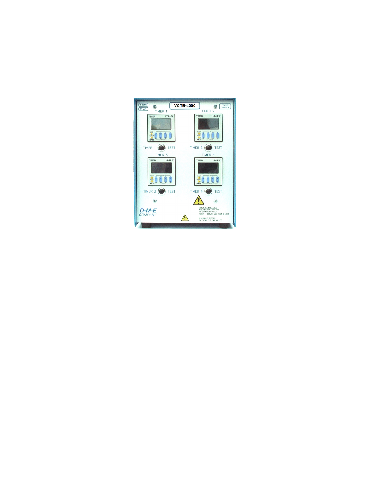
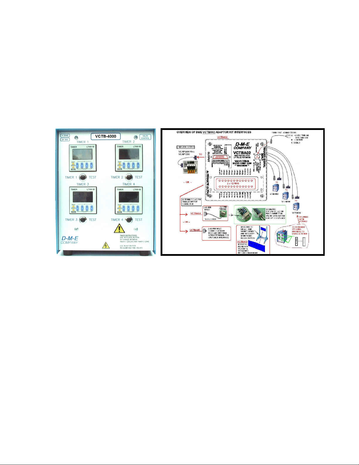
VCTB-4000
Four Zone, 24 Volt DC
Valve Gate Controller
GENERAL DESCRIPTION
This manual describes the installation,
operation and servicing of the Valve Gate
Controller.
The VCTB-4000 Valve Gate Controller is
designed to provide time based control of
up to four 24 volt DC valves used to actuate
pneumatic valve gate cylinders. It can also
be used to operate some hydraulic valves.
The VCTB-4000 is small in size so that it is
extremely portable and requires minimal
counter space.
The Controller uses DIN style solid state
timers to provide long life and high
reliability. Each timer is capable of dual time
functions so that each zone can be
programmed with a delay time (timer 1) and
an on time (timer 2). The timers in turn drive
larger solid state relays that are individually
fused against faults.
The Controller is designed to operate from a
wide supply of operating voltages (88 to 264
Volts AC) so that this one device can be
used with almost any available power
source. This also makes it easier to relocate
the controller between different plants or
even different countries. The standard
product offering comes with a 125 volt AC
plug (North American Standard). This plug
may be removed and replaced with any
number of 240 VAC plugs. Units may also
be custom ordered with other plugs, as
required.
A single DB-025 cable connects the
controller to up to four remotely located
valves minimizing required wiring and air
connections, thereby making the molding
environment neater.
DME offers valve and manifold systems that
accept the DB-025 cable directly. For other
systems that have independent valve
connections, breakout boxes are available
that accept the DB-025 connector and
provide a terminal strip for individual valve
connections.
D-M-E Company VCTB-4000 Page 4
ED-0109-OT-024-( Preliminarry Rev E)
Page 5

Test buttons are available for each zone to
assist in determining the correct hookup of
each of the valves.
UNPACKING AND INSPECTION
After unpacking, inspect your controller and
check for any damage that may have
occurred during shipment.
Check for proper operation of power switch
by turning the switch on and off with no
voltage applied.
Check all electrical connectors for visual
damage.
If any damaged is observed, return the
controller to D-M-E for repair or
replacement.
INSTALLATION
You are installing a piece of electronic
equipment, which should not be subjected to
any physical or environmental abuse.
Select a cool, dry, well-ventilated,
environmentally clean location, away from
heat, moisture and liquid carrying lines, i.e.:
water cooling hoses, hydraulic hoses, etc.
Connection of Trigger Signal
Using the cable supplied with the controller,
connect the controller to the injection
molding machine. The best way to
accomplish this is to supply a dry contact
(relay) closure that is triggered by the
injection forward signal of the molding
machine. A solid state relay contact can be
also be used. It should source power from
contact A to contact C.
Alternatively, a limit switch that is operated
from mold closure can be used as the
trigger signal. The limit switch can be
mounted to the tie bar to catch the closing
of the moving half of the mold. It may also
be mounted to the mold to detect contact of
the mold halves.
Contact B of the connector supplies a
ground signal to provide shielding of the
cable assembly.
Connection of Controller to Valves
Use an appropriate length DB-025 cable
with a male connector on one and a female
on the other to connect from the controller
to the valves. The cable must have
conductors with a minimum size of 20
gauge to run hydraulic valves.
Conductor numbers 1, 2, 3 and 4 supply
+24 VDC power to valves 1, 2, 3 and 4,
respectively. Conductor 13 supplies ground
to all of the valves.
Connection of AC Power to Controller
The standard offering of the controller is
provided with a 120 VAC connector. The
controller is designed to run from any
voltage between 88 VAC and 264 VAC.
Connect the brown conductor of the power
cable to L1 (or hot), the blue conductor to L2
(or neutral) and the green conductor with the
yellow stripe to ground. Do not operate the
controller without the ground conductor
connected.
NOTE: ALL NATIONAL AND LOCAL
ELECTRICAL CODES MUST BE
FOLLOWED WHEN CONNECTING THIS
EQUIPMENT.
Trigger Signal Connection
Black
Red
A
C
B
OPERATION
Timer Setup
Do not perform this step until all electrical
connections are performed.
Turn controller power on. The timer displays
should illuminate. If they do not illuminate,
see the Maintenance and Repair sections
below.
Each timer unit has two internal timers.
Timer 1 sets the delay between when the
trigger signal is received and the valve is to
open. This is referred to as the “delay”
D-M-E Company VCTB-4000 Page 5
ED-0109-OT-024-( Preliminarry Rev E)
Page 6

timer. Timer 2 sets the duration the valve is
open. This is referred to as the “on” timer.
Use the SET/LOCK button on the front of
the timer to select between the delay timer
(Timer 1) and the on timer (Timer 2). The
Timer unit front panel will display which
timer is selected. (See page 8)
Use the up and down arrow buttons below
the display to set the desired time value.
Each time value can be set to any value
between 00.00 seconds to 99.99 seconds.
To set any valve to open immediately, set
the delay timer (Timer 1) value to 00.00
seconds.
If the sum of the delay and the on timer is
set to a value larger than the time the
trigger signal is active, internal electronics
will automatically reset the timers at the end
of the trigger signal.
When triggered, “Timer 1” (delay timer) of
each of the timers will be displayed. The
timer will count down until it reaches zero.
When Timer 1 reaches zero, Timer 2 (on
timer) will be displayed and the timer will
count down until it reaches zero. If the
Timer 1 value is zero, Timer 2 will be
displayed when the trigger signal is
displayed, Timer 1 will not be displayed.
Proper setting of each of the “on” timers is
determined by part weight or size. For most
applications, the on timer should run
through the injection fill phase and into the
pack (and hold, if present) phases of the
injection molding machine.
NOTE: The TEST buttons on the front panel
do not actuate the timers. The buttons
bypass the timers and actuate the solid
state relays directly.
The test buttons below each of the timers
can be used to verify correct connection to
the valve gates. Warning!: verification
should be performed with the operator
gates closed to prevent injury from hot
plastic.
Verify correct operation of the timers once
the trigger signal is applied.
MAINTENANCE AND REPAIR
NOTE: DISCONNECT POWER BEFORE
SERVICING. ONLY ELECTRICIANS OR
TRAINED SERVICE PERSONNEL
SHOULD REMOVE ACCESS PANELS TO
SERVICE INTERNAL COMPONENTS.
Timers Do Not Illuminate
Make sure controller is plugged in and that
outlet power is on. Some molding machine
outlets may not be energized if machine
power is off.
If controller is plugged in and outlet has
power, check fuses 1 and 2 on top of the
controller. See the figure of the top plate.
Use only ABC-3 fuses as replacements.
(See page 7).
If a single timer does not illuminate, it may
require replacement. See timer replacement
at the end of this section. The timers are
designed to operate for 10 million cycles so
they should not require replacement very
often.
Timers Illuminate But Don’t Run
Check the trigger signal cable and make
sure it is connected. If the cable is
connected, disconnect the cable from the
controller and ensure the molding machine
provides a contact closure when expected
by checking the signal between pins A and
C.
If you can see a contact closure between
pins A and C. You can also check for the
presence of 24 volts DC between pins A and
C of the trigger signal connector on the top
of the unit.
Timer(s) Run But Valve(s) Don’t Open
Check cable connection(s) between the
controller and the valve(s). If cable damage
is suspected, replace the cable.
If the valve cable is determined to be good,
check the small fuses on top of the internal
solid state relays. If any of these fuses are
determined to be open, check the affected
zone valves and cable connections for short
D-M-E Company VCTB-4000 Page 6
ED-0109-OT-024-( Preliminarry Rev E)
Page 7

circuits. Replace defective fuses only after
determining that the related valves and
connections are in good order. The
controller was designed to run valves with
coil powers as high as 31 watts.
If the fuses on top of the solid state relays
are good, it is possible that a solid state
relay may require replacement.
Replacement fuses and relays are available
from DME. See page7.
Timer Replacement
If timer replacement appears to be
necessary, we recommend returning the unit
to DME or have it serviced by another
known qualified service technician.
Replacement timers are available from
DME. Use part number RPM-0100.
The replacement timer must be setup
before installation. A small access plate on
the right side of the timer gives access to a
bank of small switches. Open the plate. Set
all switches except switch number four to
“ON”. Replace the damaged timer making
sure to locate all wires in the proper
location. Tighten all unused screws. The
provided instructions also give details on
correct mounting of the timer.
The first time the unit is powered up, set the
timer to “Integrate A” mode by performing
the following: (1) Press and hold the
SET/LOCK button, (2) Press the right most
up or down arrow, (3) Release the
SET/LOCK button, (4) Continue pressing
the right most up or down arrow until “In-A”
is displayed, (5) Press the reset key. The
timer is now ready for use.
OUTPUT CURRENT LIMITATIONS
The controller is designed to power four
valves with a maximum power requirement
of approximately 31 watts each. This is
usually sufficient to power hydraulic valves
typically used with valve gate controls.
CONNECTORS AND CABLES:
The required power and trigger signal
cables are provided with the controller.
RETURN POLICY
The D-M-E® VCTB-4000™ is warranted for 1-year parts
and labor, excluding fuses. Contact D-M-E Customer
Service for return authorization for repairs, or warranties.
Replacement parts are also available through the
Customer Service Department.
D-M-E Customer Service
In U.S.: 1-800-626-6653
In Canada: 1-905-677-6370
SERVICE CENTER U.S.A.
D-M-E WORLD HEADQUARTERS
29111 STEPHENSON HIGHWAY
MADISON HEIGHTS, MICHIGAN 48071
TELEFAX: (248) 398-6174
D-M-E® is a registered trademark of D-M-E Company.
REPLACEMENT PARTS
DESCRIPTION
Fuse 1 and 2 ABC-3
Solid State Relay Fuses
(T5 series, 4 amp, 250
VAC)
Solid State Relay RPM-0099
Replacement Timer RPM-0100
Trigger Cable RPM-0101
CATALOG
NUMBER
RPM-0098
D-M-E Company VCTB-4000 Page 7
ED-0109-OT-024-( Preliminarry Rev E)
Page 8

2
Shield
1
5
2
3
NOTE: TRIGGER INPUT #5 (Customer Connection to Trigger signal dry contact – Injection Forward)
1. Power switch
2. Main Fuses: replace with
3. Power Entry Cord
4. Valve Output Connector
5. Trigger Signal Input
Trigger Signal Connection
TOP PLATE
Bussman ABC-3 only!
Black
Red
A
C
B
Note: Valve Output Valve # 4 Above
PINS 1, 2, 3 and 4 supply +24 VDC Control power to valves 1, 2, 3 and 4, respectively. PIN 13 supplies
ground to all of the valves.
D-M-E Company VCTB-4000 Page 8
ED-0109-OT-024-( Preliminarry Rev E)
Page 9

2
1
INSIDE OF UNIT WITH REAR COVER REMOVED
(AS VIEWED FROM REAR OF UNIT)
1. Solid State Relays (zone 1 closest,
zone 4 furthest)
2. Solid State Relay Fuses (replace
with T5 series, 4 amp, RPM-0098)
Use SET/LOCK button to
(delay) and T2 (on) timers.
Use up and down arrows
to change time values
TIMERS
change between T1
TIMER SETUP
Set all switches except 4
to ON (as shown).
Switches are on right
side of timer behind a
cover plate
TIMER TEST BUTTON
The button below each of the
timers can be used to test the
associated valve. The button
does not activate the timer
D-M-E Company VCTB-4000 Page 9
ED-0109-OT-024-( Preliminarry Rev E)
Page 10

Instructions Installation Instructions for the
VCTBA-01 Valve Gate Control Interface Accessory
( Cable is wired for 8 zones, but only controls 4 zones when connected to the VCTB4000 as shown below )
VCTBA01 shown with 2x8 Polyvalve Assembly VCTBA01 shown connected to VCTB4000 & Polyvalve Assemby
VCTBA01 ACCESSORY: VCTB4000 TO POLIVALVE 2X8 CONNECTOR
D-M-E Company VCTB-4000 Page 10
ED-0109-OT-024-( Preliminarry Rev E)
Page 11

Installation Instructions for the
VCTBA-02 Valve Gate Control Interface Accessory
& Support Accessories VCTBA-03, VCTBA-04 & VCTBA-05
D-M-E Company VCTB-4000 Page 11
ED-0109-OT-024-( Preliminarry Rev E)
Page 12

ASSEMBLY INSTRUCTIONS
Step 1. Assemble the VCTBA03 “VCTB-4000 Mounting Plate”
to the mainframe floorstand using the supplied hardware.
The mounting plate is designed to work with either the standard
“G” Series ® MFS512G or Integrity ® IFSS1000 or IFSA1000
(with or without the upright extension kit IFSE1000).
Step 2. Install the VCTB-4000 mounting studs provided with the
VCTBA03 mounting plate. The mounting plate can accommodate
one, two or three VCTB-4000 controllers.
The photo below illustrates controller positioning.
Step 3. The VCTBA02 interface accessory is to be installed on
the back side of the mounting plate. Use the (4) large flush head
bolts provided in the kit.
Step 3a. The large flush head bolts should be fastened to the
mounting plate using the provided nuts and washers.
Step 3b. When using the VCTBA02 mounted behind the VCTB4000 controllers it will be necessary to install the provided flat
washers behind the (2) center position VCTB-4000 mounting
studs.
D-M-E Company VCTB-4000 Page 12
ED-0109-OT-024-( Preliminarry Rev E)
Page 13

Step 4. Install the VCTBA02 on the studs installed in step 3
above. Note the direction of the control and trigger cables (in the
upward direction).
Step 7. Route and connect each of the three VCTBA02 trigger
cables to the associated VCTB-4000 controllers. A zone number
label identifies the cable ends.
Step 5. Install the supplied zone labels and write the associated
valve gate control zone number in the label box with an indelible
marker. NOTE that each VCTB-4000 four controllers need to be
grouped together. For example, VCTB-4000 #1 will become
zones 1-4, VCTB#2 will become zones 5-8, and so on.
Step 6. Route and connect each four-zone valve control cables of
the VCTBA02 to the associated zoned VCTB-4000 controllers. A
zone number label identifies the cable ends.
Step 8. Connect the TRIGGER INPUT CABLE of the VCTBA02
to the molding machine +24 VDC injection forward signal.
NOTE THAT THE TRIGGER INPUT OF THE VCTBA02 IS
NOT A DRY CONTACT CLOSURE CONNECTION! The
VCTBA02 trigger input requires +24 VDC to trigger the
connected VCTB-4000 controllers.
Step 9. Connect the VCTBA01 eight zone valve control cable to
the standard DB-25 output connector of the VCTBA02, and
connect to the mold valve gate control input connector.
D-M-E Company VCTB-4000 Page 13
ED-0109-OT-024-( Preliminarry Rev E)
Page 14

- OR –
Connect the VCTB04 eight zone control cable to the “alternate”
output connector of the VCTBA02.
P/N: VCTBA05
A twelve-zone control cable connection can be made using the
twelve-zone accessory output mating cable connector kit
VCTBA05.
Step 10. Mount the temperature control mainframe to the
MFS512G mainframe floorstand.
A standard MFP12G is shown above. To mount a standard
MFP8G, use the mainframe adapter plates provided with the
MFS512G floorstand kit.
Alternative Mounting: The VCTBA03 mounting plate can also
be mounted below the standard mainframe as shown above. To
use this mount, the VCTB-4000 mounting studs on the mounting
plate must be installed in the lower position. Also, will be
necessary to route the VCTBA02 control and trigger cables
between the mainframe and mounting plate before either is
mounted to the stand.
D-M-E Company VCTB-4000 Page 14
ED-0109-OT-024-( Preliminarry Rev E)
Page 15

NOTES:
ECN’S:
ECN-0622 Changed Model Number from TGV-4000 to VCTB-4000
ECN-0627 Changed pin out of valve connector
ECN-0651 Changed warranty period from 1 to 3 years
ECN-XXXX Preliminary REV E - Added VCTBA-01, VCTBA-02, VCTBA-03, VCTBA-04,
VCTBA-05 Assembly Instructions.
APPROVAL:
SENIOR PRODUCT ENGINEER: _____________________________ DATE: ______________
MANAGER OF ELECTRONICS: ______________________________ DATE: ______________
D-M-E Company VCTB-4000 Page 15
ED-0109-OT-024-( Preliminarry Rev E)
 Loading...