

Page 1
ME-X741-PS-421(B)
3-14
PSHOT625
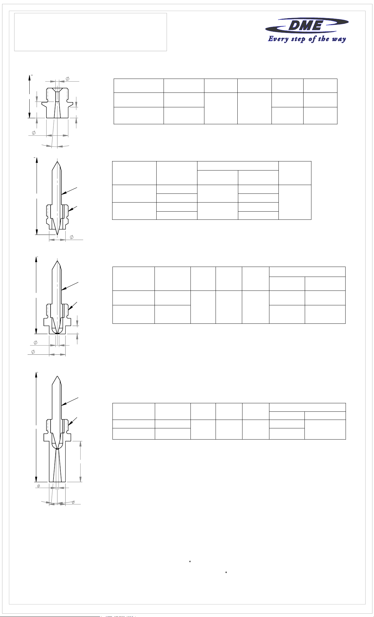
625 SERIES TIP SUB-ASSEMBLIES
PACKING SLIP
Tip Sub-Assemblies
"B"
"A"
"C"
"
A"
"T"
"L"
5°
PER SIDE
NEEDLE
RETAINER TIP
All 625 Series tips have 1"-16 UN threads
Sprue Gate/Extended Sprue Gate
TIP
SPRUE GATE
EXTENDED
SPRUE GATE
ITEM
NUMBER
"B" DIA.
EHT0022
.187
EHT0023
Point Gate (Bodyless)
TYPE
STANDARD
WEAR
RESISTANT
ITEM
NUMBER
EHT1306
EHT1311 EHT0326
EHT1307
EHT1310 EHT1354
NEEDLE
EHN0019
EHN0402
"T" DIA.
1.000
INCLUDES
RETAINER
EHT1354
EHT0326
TIP
"L"
"C"
.250 .500
1.000 1.250
"T" DIA.
.625
"A"
"O"
"T"
"A" + .750
"T"
NEEDLE
RETAINER TIP
"E"
NEEDLE
RETAINER TIP
Point Gate (Full Body)
TYPE
STANDARD
WEAR
RESISTANT
ITEM
NUMBER
EHT2021
EHT2022
"T" DIA.
1.000
Extended Point Gate (Full Body)
TYPE
STANDARD
WEAR
RESISTANT
ITEM
NUMBER
EHT2321
EHT2322
"T" DIA.
1.000
"O" DIA.
.125 .250
"O" DIA.
.125
"E"
"E"
1.000
INCLUDES
NEEDLE
EHN0019
EHN0402
INCLUDES
NEEDLE
EHN0019
EHN0402
RETAINER
TIP
EHT0036
EHT1326
RETAINER
EHN2336
"E"
"O"
5°
PER SIDE
"T"
For selection of gate diameter it is important to take into consideration the materials flow characterisitics, shear rate of resin, molding
conditions, fill time requirements, gate vestiage, wall thickness and configuration of part to be molded. Situations requiring high injection
velocities must be considered when selecting small gate diameters. High injection rates may require larger gates due to shear heat build
up (e.g. high weight thin wall applications). See material manufactures literature for further information regarding materials to be molded.
To compensate for nozzle's growth when heat is applied, the linear expansion of the nozzle (BE) at a given temperature must be added
to the nominal "A" dimension (See catalog for "A" lengths). The formula below shows how to figure boringing depth (dimension "A" + BE)
The tip of the nozzle will now be flush with the cavity line at processing temperature.
Formula for determining this expansion factor is as follows:
BE = "A" dimension x 0.0000063 x (Nozzle set point temperature - 68
EXAMPLE: Given a 4 inch "A" dimension, with a nozzle set point temperature of 500
BE = 4 x 0.0000063 x (500 - 68) = 0.011
Thus "A" + BE will be 4.011
Note: the above information is only given as an example, variations may occour based on mold configurations and cooling factor. In some
instances it may be nessessary to obtain an empirical factor.
F)
F:
Page 2
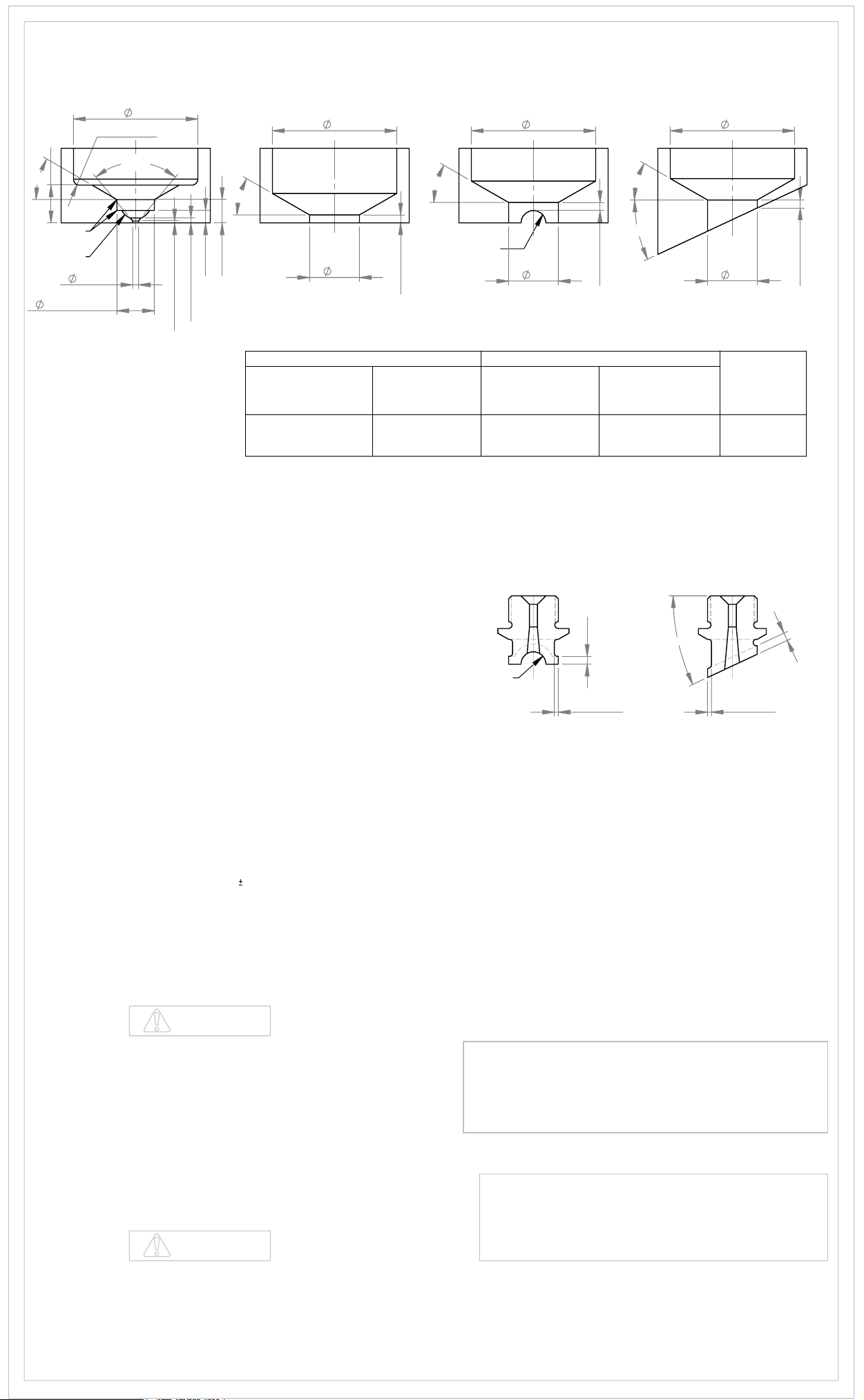
625 SERIES GATE MACHINING DIMENSIONS
0.47
30°
R.010-.015
R.312
0.6250
POINT GATE
(BODYLESS)
"N"
R0.125
80°
"O"
+
0.0005
0.0000
30°
.125
.235
.020 AT TANG.
.005 LAND MAX.
STD. SPRUE AND
POINT GATE
(FULLBODY)
"N"
+.0005
-.0000
"S"
.08 MIN.
"O" DIA.
UNFILLED RESIN
FILLED RESIN
.080 MIN. .100 MIN.
EXTENDED SPRUE
AND EXTENDED POINT
GATE (FULL BODY)
RUNNER DESIGN
30°
CUSTOMER
RADIUS TO
SUIT
+.0005
-.0000
"S"
SQ. COIL OR
CAST-IN
2.125 MAX.
30°
25°
MAX.
.08 MIN.
"N" DIA.
SQ. COIL OR
CAST-IN
1.875 MIN.
EXTENDED SPRUE
AND EXTENDED POINT
GATE (FULL BODY)
ANGLE DESIGN
"N""N"
+.0005
-.0000
"S"
.08 MIN.
"S" DIA.
1.0005
OPERATING & SERVICING INSTRUCTIONS:
All interchangeable nozzles are similar, and differ only in size and material flow
capacity.
OPERATING PROCEDURE
The nozzles are supplied with a Square (Flat) Coil or Cast-In heater equipped
with a Type "J" Thermocouple.
It is recommended to use a DME closed loop Temperature Controller for optimum
temperature control with Step Smart or Smart Step . These systems will allow
heater to dissipate any moisture and then change automatically to set point. It is
essential to use controllers with the proper votage and wattage capabilities. The
voltage and wattage of each heater is clearly marked on the heater tag. Step
Smart , Smart Step and DME are all registered trademark of DME company.
DISASSEMBLY PROCEDURE
1. Nozzle has been designed to have the tip removed in the press.
2. For removal of tip from nozzle, a 6 point deep well socket is recommended. The
nozzle must be at processing temperature and the heater should be turned off
when removing tip counter-clockwise from the nozzle.
ASSEMBLY PROCEDURE
1.Tip and nozzle thread area must be clean of any material before reassembling.
2. Apply an anti-seize compound on the tip threads.
3. Torque tip into the shank of the nozzle body. Torque and untorque two or three
times making sure there is a good contact between the tip and the nozzle.
Torque the tip into the nozzle using 30
point deep well socket is recommended.
5 ft-lbs. For protection of the tip a six
EXTENDED SPRUE
AND EXTENDED POINT
GATE (FULL BODY)
RUNNER DESIGN
MACHINING
.08
CUSTOMER
RADIUS TO
SUIT
Nozzle body head must be keyed to prevent body from turning when tip is
installed into body. Customer to torque tip into shank of nozzle body in mold
three times to set tip before marking the runner or angle on the tip. This will
ensure that the tip will line up after runner or angle is machined onto tip.
Customer may machine relief on Extended Sprue Gate Tips for molding
heat sensitive or engineering grade materials. (see drawings above)
.04-.06 .04-.06
EXTENDED SPRUE
AND EXTENDED POINT
GATE (FULL BODY)
ANGLE DESIGN
MACHINING
25°
MAX.
.08
IMPORTANT SAFETY INFORMATION
A hot-runner system includes electrical elements and may contain molten
plastic at elevated temperature and pressure. To avoid injury, exercise caution
by reading these instructions before servicing or operating the system.
These instrutions must be passed on to the end user where they should be
read before using this product. Failure to do so can result in serious injury or
death.
DANGER
Failure to comply will result in serious injury or death.
ELECTRICAL HAZARDS
Improper voltages or grounding can result in electrical shock. Use only with
proper voltage and a proper earth ground.
To avoid electrical shock, do not operate product when wet
Do not operate this equipment with covers or panels removed.
To avoid electrical shock, turn off main power disconnect and lockout/tag out
before servicing this device. Do not connect temperature sensor to electrical
power. It will damage the product and it could cause fire, severe injuries or even
death.
If green ground wire present, wire must be connected to the ground.
Do not rebend rigid leads. Rebending leads might result in damage to circuit.
Product might absorb moisture when cool. Use Voltage or power to drive out
residualmoisture before applying full power. Failure to do so may cause damage
to this product.
WARNING
Failure to comply can result in serious injury or death.
STORED ENERY AND HIGH TEMPERATURE HAZARDS
This product maintains molten plastic at high pressure. Use caution when
operating ans servicing the system.
Physical contact with molten plastic may result in severe burns. Proper
protective equipment, including eye protection, must be worn.
This product has heated surfaces. Use cation when operating ans servicing the
system to avoid severe burns. Proper protective equipment should be worn.
DME SHALL NOT BE LIABLE FOR MISUSE OR FAILURE TO
FOLLOW THE ENCLOSED INSTRUCTIONS AND SPECIFICATIONS.
DME HEREBY TO DISCLAIMS ALL IMPLIED WARRANTIES,
INCLUDING MERCHANTABILITY AND FITNESS FOR A PARTICULAR
PURPOSE IN NO EVENT SHALL DME BE RESPONSIBLE FOR LOSS
OF USE, REVENUE OR PROFIT, OR FOR INCIDENTAL OR
CONSEQUENTIAL DAMAGED.
ME-X741-PS-421(B)
3-14
PSHOT625
625 SERIES TIP SUB-ASSEMBLIES
PACKING SLIP
DME
29111 STEPHENSON HIGHWAY
MADISON HEIGHTS
MICHIGAN 48071 USA
US 800-656-6653
CANADA 800-387-6600
www.dme.net
 Loading...