

Page 1
ME-G55-0512-G 11-2010 SXP9997
INSTALLATION DATA FOR STELLAR WITH
HIGH PERFORMANCE HEATER
a) SXF5000 or SXF5100 retainer used with
SXT4010, SXT5010 or SXT5200 TIPS
b) SXT1040 - Sprue Tip
Please read carefully before installing
and/or removing nozzle from mold
FOR NOZZLE BODY P/N'S:
SXB4048, SXB4068, SXB4088, SXB4108,
SXB4128 & SXB4148
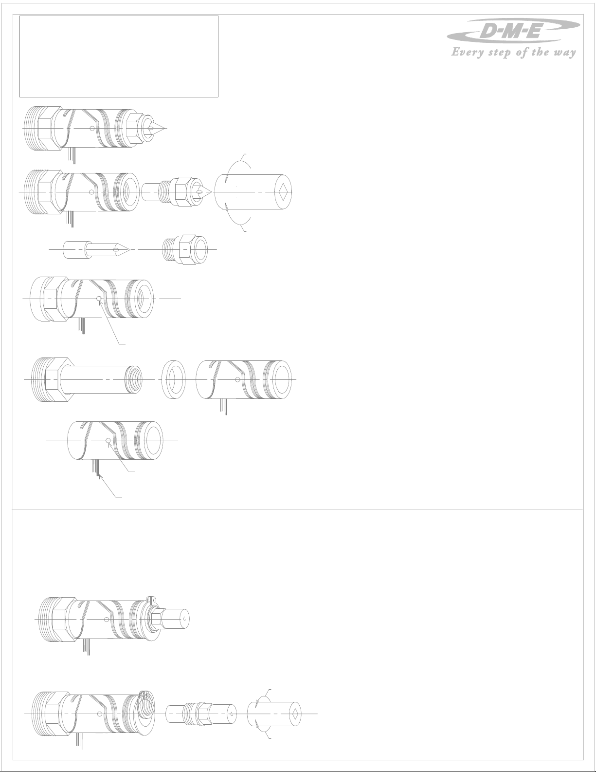
Fig. #1
Fig. #2
Fig. #3
Fig. #4
Removal Holes
Fig. #5
Removal Holes
REMOVE
SXW0003
10mm deep well
6 point socket
ASSEMBLE
10. If the heater is hard to remove use the removal holes placed
11. Bend heater and thermocouple leads only if needed to better fit
12. Slide spacer and heater over nozzle body
13.
14. Assemble tip into retainer.
15. Thread retainer clockwise into the nozzle body and torque to 11.3Nm
(8.3 ft-lbs/100 in-lbs) using DME Catalog No. SXW0003, 10mm
HEATER REPLACEMENT INSTRUCTIONS
FOR POINT GATE AND THRU HOLE TIPS
1. STELLAR nozzle sub-assembly with tip sub-assembly. (see Fig. #1)
Threaded style nozzle with point gate tip shown.
2. Safety glasses and gloves should be worn when working on the mold.
3. Turn nozzle heater on, and set at 10-38°C (50-100°F) below set
point of processing temperature to allow for easier tip removal.
4. Carefully clean plastic material from around tip and retainer.
5. Remove retainer with 10mm deep well 6 point socket turning
counterclockwise.(see Fig. #2) Socket will fit over the front seal
off area when placed on retainer hex.
DO NOT DAMAGE SEAL OFF AREA.
6. Carefully remove tip from retainer. (see Fig. #3) Inspect seal
off area for out of roundness and/or score marks and replace
retainer if either condition occurs. Inspect tip for any wear and
replace if wear has occurred.
7. Clean plastic material from thread and counterbore areas in nozzle
body to ensure proper assembly. (see Fig. #4)
8. Turn off nozzle heater and disconnect heater and thermocouple
leads from connectors on mold. Allow nozzle time to cool down.
9. Remove heater and spacer from nozzle body.
(see Fig. #5)
180 deg apart on the heater body. (see Fig. #4)
Do not use the leads to pull the heater off.
in the wire channel.
For most cases the heater leads will exit into the wire channel.
CAUTION !
REPEATED BENDING OF HEATER AND THERMOCOUPLE LEADS CAN
FRACTURE LEAD WIRES. TRY TO BEND ONLY ONCE, IF POSSIBLE.
(see Fig. #5).
DO NOT LUBRICATE OR USE ANTI-SEIZE ON RETAINER THREADS.
deep well 6 point socket tool and torque wrench. (see Fig. #2)
16. Wire heater and thermocouple leads to connectors on mold.
Fig. #6
T/C wires, Black (+) & White (-)
1. STELLAR nozzle sub-assembly with tip installed. (see Fig. #10)
Threaded style nozzle and sprue gate tip shown.
2. Safety glasses and gloves should be worn when working on the mold.
3. Turn nozzle heater on, and set at 10-38°C (50-100°F) below set
point of processing temperature to allow for easier tip removal.
4. Remove sprue gate tip with a 8mm deep well socket turning
counterclockwise. Do not damage 7mm diameter seal-off area or
front molding surface (see Fig# 11).
5. Clean plastic material from nozzle and tip threads. Also, clean
plastic material from tip counterbore in nozzle body to ensure
proper assembly.
Fig. #10
6. Turn off nozzle heater and allow to cool down.
7. Remove Heater Clip with Snap Ring Pliers.
8. Follow steps #9 to #12 from "Instructions for Point gate and thru hole tips".
REMOVE
8mm
Fig. #11
ASSEMBLE
HEATER REPLACEMENT INSTRUCTIONS
FOR SPRUE GATE TIPS
9. Place Heater Clip onto Nozzle Body using Snap Ring Pliers.
10. DO NOT LUBRICATE OR USE ANTI-SEIZE ON THREADS.
11. Thread tip clockwise into the nozzle body and torque to 16Nm
(12ft-lbs/144in-lbs) using a 8mm deep well socket
and torque wrench
12. Wire heater and thermocouple leads to connectors on mold.
(see Fig#11).
Page 2
ME-G55-0512-G 11-2010 SXP9997
INSTALLATION DATA FOR STELLAR WITH
HIGH PERFORMANCE HEATER
a) SXF5000 or SXF5100 retainer used with
SXT4010, SXT5010 or SXT5200 TIPS
b) SXT1040 - Sprue Tip
Please read carefully before installing
and/or removing nozzle from mold
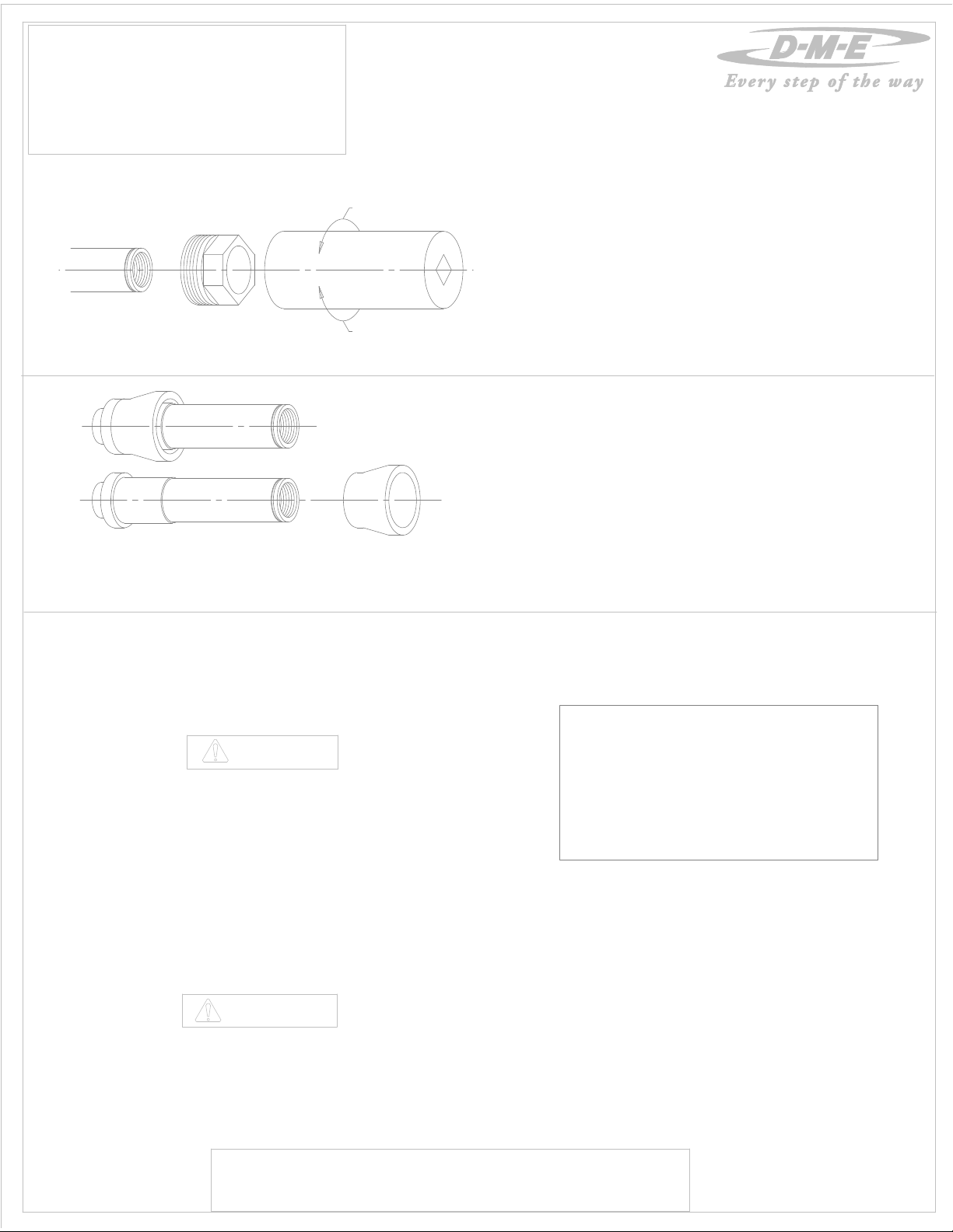
Fig. #7
NOZZLE BODY (THREADED STYLE) REMOVAL INSTRUCTIONS
NOTE: NUT SOCKET TOOL SXW0002 SHOULD BE ORDERED SEPARATELY.
REMOVE
SXW0002
ASSEMBLE
1. Steps #1 thru #9 of Instructions for Point Gate and thru hole tips
must be taken before nozzle can be removed from manifold.
2. Remove nut counterclockwise with socket tool
D-M-E cat. no. SXW0002 (see Fig. #7).
3. Remove nozzle body from manifold.
4. Clean plastic material from thread and counterbore
areas in manifold to ensure proper assembly.
5. Apply high temperature anti-seize compound to nut threads to
prevent galling or seizing. Use Fel-Pro C5A or equivalent
anti-seize compound.
6. Place nozzle body into manifold and thread nut clockwise into the
manifold and torque
to 81Nm (60 ft-lbs) using nut socket tool.
7. Follow steps #11 thru #16 of "Intructions for Point Gate &
Thru Hole hole tips" for final assembly".
8. Reassemble manifold into the mold.
NOZZLE BODY (COMPRESSION STYLE) REMOVAL INSTRUCTIONS
Fig. #8
Fig. #9
IMPORTANT SAFETY INFORMATION
A hot-runner system includes electrical elements and may contain molten
plastic at elevated temperature and pressure. To avoid injury, exercise
caution by reading these instructions before servicing or operating the
system.
These instructions must be passed on to the end user where they should
be read before using this product. Failure to do so can result in serious
injury or death.
DANGER
Failure to comply will result in serious injury or death:
ELECTRICAL HAZARDS
Improper voltages or grounding can result in electrical shock. Use only
with proper voltage and a proper earth ground.
To avoid electrical shock, do not operate product when wet.
Do not operate this equipment with covers or panels removed.
To avoid electrical shock, turn off main power disconnect and lockout /
tag out before servicing this device. Do not connect temperature sensors to
electrical power. It will damage the product and it can cause fire, severe
injuries or even death.
If green ground wire present wire must be connected to the ground.
Do not rebend rigid leads. Rebending leads might result in damage to circuit.
Product might absorb moisture when cool. Use low Voltage or power to drive
out residual moisture before applying full power. Failure to do so may cause
damage to this product.
1. Steps #1 thru #9 of Instructions for Point Gate and thru hole tips
must be taken before nozzle can be removed from mold.
2. Carefully remove manifold from mold base.
3. Remove nozzle body from manifold.
4. Remove nozzle head from nozzle body (see Fig. #8 & Fig. #9).
5. Carefully clean area where nozzle body and
manifold seat together.
6. Assemble nozzle head and nozzle into nozzle plate.
7. Reassemble manifold into the mold.
8. Follow steps #11 thru #16 of "Intructions for Point Gate &
Thru Hole hole tips" for final assembly.
9. Reassemble manifold into the mold.
WIRING INFORMATION
High Performance Heaters are supplied with 2"
pre-stripped 46" long leads.
Heaters are 230 VAC.
2 power leads are MULTI COLOR
1 ground lead is GREEN.
Thermocouples are "J" Type.
Thermocouples are supplied with 46" long leads.
1 T/C lead is WHITE and negative (-) constantan
(non-magnetic).
1 T/C lead is BLACK and positive (+) iron (magnetic).
WARNING
Failure to comply can result in serious injury or death:
STORED ENERGY AND HIGH TEMPERATURE HAZARDS
This product maintains molten plastic at high pressure. Use caution when
operating and servicing the system.
Physical contact with molten plastic may result in severe burns. Proper
protective equipment, including eye protection, must be worn. This product
has heated surfaces. Use caution when operating and servicing the system
to avoid severe burns. Proper protective equipment should be worn.
D-M-E SHALL NOT BE LIABLE FOR MISUSE OR FAILURE TO FOLLOW THE ENCLOSED
INSTRUCTIONS AND SPECIFICATIONS. D-M-E HERBY TO DISCLAIMS ALL IMPLIED
WARRANTIES, INCLUDING MERCHANTABILITY AND FITNESS FOR A PARTICULAR
PURPOSE. IN NO EVENT SHALL D-M-E BE RESPONSIBLE FOR LOSS OF USE, REVENUE
OR PROFIT, OR FOR INCIDENTAL OR CONSEQUENTIAL DAMAGED.
D-M-E COMPANY
29111 STEPHENSON HIGHWAY
MADISON HEIGHTS
MICHIGAN 48071 USA
US 800-656-6656
CANADA 800-387-6600
www.dme.net
 Loading...