

Page 1
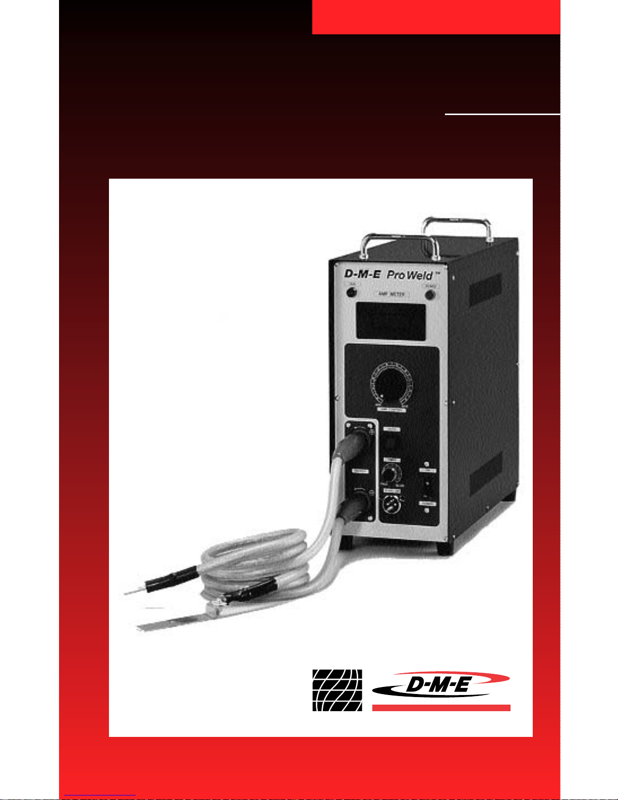
D-M-E
Pro W eld
™
USER GUIDE
Page 2

D-M-E Pro Weld
™
User Guide
PREFACE
Please read this instruction manual thoroughly before using
your D-M-E Pro Weld™system.
The D-M-E Pro Weld unit is a newly developed resistancetype micro-welding machine. It is powerful enough to weld
0.3mm thick metal sheets and has a wide selection of welding materials in sheet, wire and powder form to choose from.
Applications
♦ Welding can be made to steel molds and dies for plastics,
rubber, die casting, and compression molds.
♦ Welds can be applied on as-rolled steel, pre-hardened
steel, quenched and tempered steel, free cutting steel,
stainless steel, and others.
♦ To build up parting lines, mold seams, 3-point corners
and edges.
♦ To fill in pores, repair of pinholes.
♦ To repair wear, worn areas on slides, ejector pins,
sharp edge molds, and thin core par ts.
♦ To design modification of inser ts and cores.
♦ To add a radius to an inner corner due to a
design change.
♦ To repair the shrinkage that occurs after argon arc
and TIG welding.
♦ To repair damage due to overgrinding, from an
end mill or EDM process.
Page 3

D-M-E
Pro W eld
™
Model No. UMW0001
USER GUIDE
Page 4

2
TABLE OF CONTENTS
Applications
I. Introduction............................................................................5
Advantages 5
II. Specifications........................................................................7
Standard Accessories for Pro Weld™UMW0001 7
Additional Welding Materials 9
III. Parts Nomenclature for Pro Weld UMW0001....................11
IV. General Description of Use ................................................13
IV.1 Function 13
IV.2 Attachment of Electrodes 13
IV.3 Usage of Electrodes 13
➤ Operational Tip 14
IV.4 Start-Up Procedure 14
➤ Operational Tip 16
V. Operation ............................................................................17
V.1 Cautions in Welding Work 17
V.2 Discharge of Stored Energy 18
VI. Welding ................................................................................19
VI.1 Workpiece, Electrode, Welding Materials 19
VI.2 Pro Weld Control Features 20
➤ Operational Tip 21
VI.3 Shaping Electrodes 22
VI.4 Recommended Current Output Levels 23
VI.5 Mold Material/Welding Material 25
VI.6 Pro Weld W elding Process 27
➤ Operational Tip 28
VI.7 Roll Welding Technique 29
Table of Contents
Page 5

3
Table of Contents
VII. Examples of Welding ........................................................ 31
VII.1 Focalization of Current, Electrode Shape 31
and Formation of the Weld Spot
VII.2 Powder Metal Application 32
Welding to a 3-Point Corner, Parting Line, Edge 33
Welding to a Flat Surface 34
Welding an Inner Corner 35
Welding a Pinhole 35
Welding a Crack 36
Welding in a Rib 37
➤ Operational Tip 37
VII.3 Welding of Sheet Material 38
Proper Electrode Contact 38
Positioning of the Sheet Mater ial 38
Welding to a Flat Surface 39
Sheet Material Recession 39
Repair of a 3-Point Cor ner Collapse 40
Repair of a Parting Line or Edge 41
Repair of a Scratch or V-Notched Flaw
and Pinhole 42
Multi-Layer Padding 43
Repair of Base Metal Impurities 45
Repair of an Inner Corner 45
Welding to a Rising Wall 46
Welding to a Narrow or Concave Mold Section 46
VIII. Examples of Bad Welding Work ........................................47
VIII.1 Unconnected Weld Spots 47
VIII.2 Improperly Shaped Electrodes 47
VIII.3 Oxidized Base Metal or Electrodes 48
VIII.4 Bad Conductivity 48
IX. Maintenance Guarantee ....................................................49
Page 6

Page 7

I
I. Introduction
Please read this instruction manual thoroughly before using your
Pro Weld™system.
Pro Weld is a newly developed resistance-type welder. It effectively
builds up material to repair or redesign molds and dies. [Note: It is
not recommended for use on press dies, blow molds (usually made
from aluminum) or aluminum molds.]
The resistance welding method creates high energy discharges in
very short cycles through a capacitance circuit. Almost no heat is
created and, therefore, the base mold material is not altered or
damaged.
The Pro Weld micro welding technique is revolutionizing the repair
of molds by keeping this wor k in-house. Pro Weld welds 0.1mm,
0.2mm and 0.3mm thick metal sheets or strips, metal wire and
metal powder to the damaged area. It is extremely easy to use,
reduces downtime and improves quality.
Advantages
♦ No scaling or flaking occurs after welding as the sheet, wire and
powder metals used are free from impurities, and because the
weld has high strength, homogeneity and reliability.
♦ Easy to operate, no special training necessary.
♦ Hand and machine finishing is easier as the amount of weld
metal is not excessive.
♦ As the process emits almost no heat, there will be no shrinkage,
distortion, deformation or discoloration of the mold.
♦ No welding fumes or toxic gases are emitted.
5
Introduction
Page 8

6
Introduction
I
♦ The process is optimally suited for small areas and micro
welding.
♦ Hardening and plating can be done after welding.
♦ Welding work time is greatly reduced.Roll welding a 3/8" (10mm)
long parting line can be done in 1 minute, treating a pinhole in
30 seconds.
♦ As the capacitor system charges slowly and unloads quickly, an
input power can be used with low loading capacity.
♦ A built-in microprocessor allows stored energy to be easily
adjusted.
♦ High quality selection of welding materials in 0.1 and 0.2mm
thick metal sheet, 0.2-0.5mm diameter wire and powder metal.
♦ After the initial weld, if more padding is required, re-welding
can be done easily.
♦ Pro Weld is powerful enough to weld 0.3mm thick sheet.
Page 9
7
II. Specifications
II
Standard Accessories for Pro Weld UMW0001
Specifications
Power pack with welding cord, grounding
cord and plate, power cord, foot switch and
all accessories listed below
N51–Standard SKH-51 steel powder (50 grams)
(63 Rc; for D-2/M-2/S-7 steels)
N80–Standard NAK80 steel powder (50 grams)
(38-40 Rc; for P-20/P-21 steels)
NAK80–Standard steel sheet (10 sheets,
0.1T x 5W x 100L) (38-40 Rc; for P-20/P-21 steels)
NTA1–Ni Alloy sheet (10 sheets, 0.1T x 30W x 70L)
(135HV; for all steels)
NTA2–Ni Alloy sheet (10 sheets, 0.2T x 30W x 70L)
(135HV; for all steels)
Protective glasses
Catalog No. Description
Complete Pro Weld system includes: (Dimensions in millimeters)
UMW0001
UMW0002
UMW0003
UMW0004
UMW0005
UMW0006
UMW0007
Model Pro W eld UMW0001
Input Voltage 120 VAC
Consumable Power 600 VA
Output Power 700W
Output Voltage 0 - 9V
Output Current 0 - 1100 Amps
Control System SCR Switching System
Auto Timer On 0.5 sec.
Dimensions (inches) W6.5 x D17.75 x H16
Weight 62 lbs
Page 10
Catalog No. Description
II
Specifications
8
Protective gloves
Magnet electrode (2 dia. x 50L)
Magnet electrode (3 dia. x 50L)
Magnet electrode (4 dia. x 60L)
Magnet electrode (4 dia. x 50L)
Standard electrode (2 dia. x 50L)
Standard electrode (3 dia. x 50L)
Standard electrode (4 dia. x 50L)
Standard electrode (1.2T x 5W x 35L)
Standard electrode holder (black)
(used with UMW0015)
Magnet electrode holder (brown)
(used with UMW0011 and UMW0012)
Standard electrode holder (black)
(used with UMW0016)
Standard electrode holder (black)
(used with UMW0013)
Standard electrode holder (black)
(used with UMW0014)
Magnet electrode holder (brown)
(used with UMW0009 and UMW0010)
Tool box
Sheet metal shears
Screw and wrench set
Fuse (2A)
Insulation tape
UMW0008
UMW0009
UMW0010
UMW0011
UMW0012
UMW0013
UMW0014
UMW0015
UMW0016
UMW0017
UMW0018
UMW0019
UMW0020
UMW0021
UMW0022
UMW0023
UMW0024
UMW0025
UMW0026
UMW0027
Standard Accessories for Pro Weld UMW0001 (continued)
Complete Pro Weld system includes: (Dimensions in millimeters)
Page 11
II
9
Specifications
N-11 UMP0067 SKD-11 50 grams Rc 50-60 Min. A-2, D-2
All Die Steels
N-38 UMP0072 HPM38 50 grams Rc 30 Max. 420SS
(Prehardened)
N-39 UMP0073 PD555 50 grams Rc 50-52 STAVAX
N-40 UMP0060 Ni-Cr Alloy 50 grams Rc 36-42 All Mold Steels
N-50 UMP0062 Ni Alloy 50 grams Rc 47-53 All Mold Steels
N-61 UMP0068 SKD61 50 grams Rc 40-53 Max. H-13, 420SS
N-13 UMP0063 Ni Alloy 50 grams Rc 10-15 All Mold Steels
N-90 UMP0061 Ni Alloy 50 grams Rc 16-20 All Mold Steels
SCM, Good Choice
N-14 UMPS017 PHM-2 50 grams Rc 30-35 for P-20
SNCM, Good Choice
N-15 UMPS018 HPM17 50 grams Rc 30-35 for P-20
SNCM, Good Choice
N-16 UMPS019 2767 50 grams Rc 30-35 for P-20
N-55 UMP0071 NAK55 50 grams Rc 38-41 P-21
Welding Material: Fine Powder – Precision Work
Welding D-M-E Japanese Quantity Hardness U.S. Mold Steel
Materials Catalog No. Mold Steel Rockwell C Equivalent
SP-51 UMPS010 SKH-51 50 grams Rc 63 Min. D-2, M-2, S-7
SP-11 UMPS011 SKH-11 50 grams Rc 50 Min. A-2, D-2
SP-61 UMPS012 SKD-61 50 grams Rc 53 Max. H-13
Welding Material: Powder
Welding D-M-E Japanese Quantity Hardness U.S. Mold Steel
Materials Catalog No. Mold Steel Rockwell C Equivalent
Additional Welding Materials for Pro Weld UMW0001
Page 12
10
Specifications
II
Additional Welding Materials for Pro Weld UMW0001
Welding Material:Wire
Welding D-M-E Japanese Hardness U.S. Mold Steel
Materials Catalog No. Mold Steel Quantity / Size Rockwell Equivalent
Welding Material: Sheet
(Dimensions in millimeters)
NT-6 UMA0001 10 / 0.2T x 5w x 100L Rc 30 All Mold Steels
NS-1 UMA0054 SS Alloy 10 / 0.1T x 30w x 70L Rb 90 All Mold Steels
NS-2 UMA0055 SS Alloy 10 / 0.2T x 30w x 70L Rb 90 All Mold Steels
HPM-50 UMD0102 HPM50 10 / 0.2T x 5w x 100L Rc 38-40 P-21 Improved
HPM-38 UMD0107 HPM38 10 / 0.2T x 5w x 100L Rc 30-33 420SS
STAVAX UMD0104 STAVAX 10 / 0.2T x 5w x 100L Rc 50-52 STAVAX,420SS
SCM440,
HPM-2 UMD0101 IMPAX, 10 / 0.2T x 5w x 100L Rc 30-50 P-20
HPM-2
MAS1 UMD0103 10 / 0.2T x 5w x 100L Rc 50-53 P-20
NAK-55 UMD0106 NAK55 10 / 0.2T x 5w x 100L Rc 38-40 P-21
Welding D-M-E Japanese Hardness U.S. Mold Steel
Materials Catalog No. Mold Steel Quantity / Size Rockwell Equivalent
S2 UMA0056 SS Alloy 1 / 0.2 dia. x 5m Rb 90 All Mold Steels
S3 UMA0057 SS Alloy 1 / 0.3 dia. x 5m Rb 90 All Mold Steels
S4 UMA0058 SS Alloy 1 / 0.4 dia. x 5m Rb 90 All Mold Steels
S5 UMA0059 SS Alloy 1 / 0.5 dia. x 5m Rb 90 All Mold Steels
Page 13
11
III
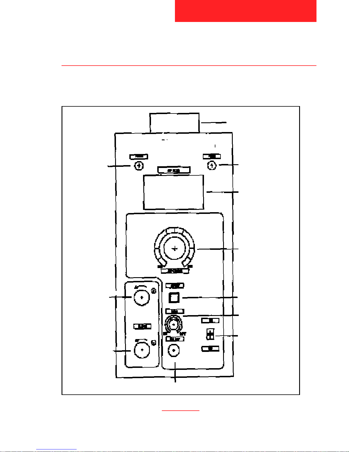
III. Parts Nomenclature for Pro Weld™ UMW0001
Parts Nomenclature for
Pro Weld™ UMW0001
D-M-E Pro Weld
™
Carrying Handle
Amp Output Meter
Slidac Amp
Output Control
Automatic/Manual
Function
Main Power
Switch
Output for
Grounding
Cord
Output for
Electrode
Holder Cord
Power Indicator
Lamp
Timer
Input for Foot Switch
Operation
Mode Lamp
Page 14
III
12
Parts Nomenclature for
Pro Weld™ UMW0001
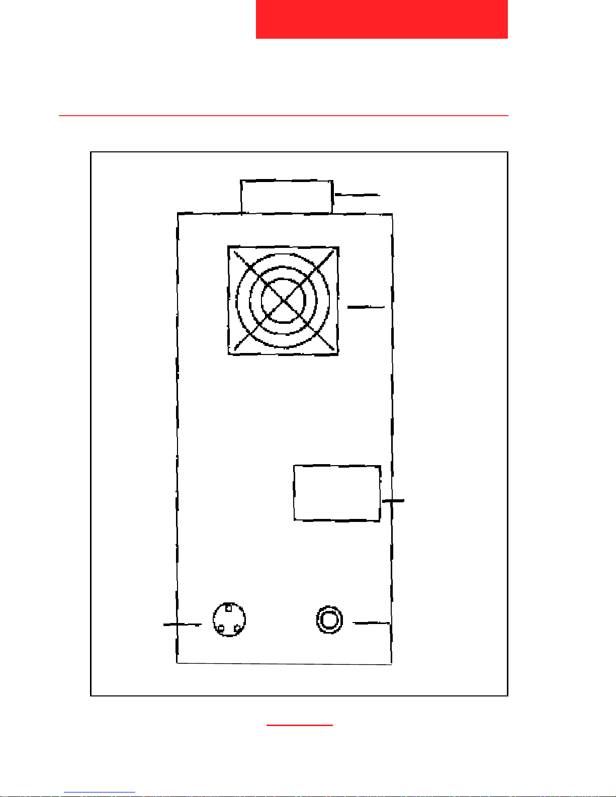
Carrying Handle
Fan
Specifications and
Serial Number
Plate
Fuse Holder/Fuse
Input Power
Socket
Pro Weld UMW0001 Back Panel
Page 15

13
IV
IV. General Description of Use
IV.1 Function
Electric power is supplied from an AC120V source. As a resistancetype micro-welding machine, Pro Weld stores current in a
capacitance circuit. Current is released by the foot switch and sent
to the electrode in the electrode holder. This release of current
causes the welding material to melt and fuse with the base metal.
IV.2 Attachment of Electrodes to the Electrode Holder
Electrodes are fixed in the Electrode Holders.To use the opposite
end of an Electrode or to replace an Electrode, use the supplied
Allen Head Wrenches. Do not over-tighten;leave approximately
25mm of the Electrode exposed.
IV.3 Usage of Electrodes
Electrodes are of two types: Magnetic Electrodes and Nonmagnetic Electrodes. Magnetic Electrodes are pre-mounted in the
brown Electrode Holders. Use these Electrodes to pick up metal
welding powders and for tacking powders on the mold repair area.
Non-magnetic Electrodes are fixed in the black Electrode Holders.
Use these to tack welding sheet and wire and to weld in place
powders, sheet and wire.
General Description of Use
Page 16

IV
Operational Tip
When using Magnetic Electrodes apply less pressure to
the workpiece. Do not exceed the Amp output guidelines
(see VI.4). To do so could cause the Electrode to demagnetize.
Apply more pressure to the work surface when using
non-magnetic Electrodes. Again, follow the Amp output
guidelines.
Use only Pro Weld Electrodes.The manufacturer does
not accept liability for other manufacturers’ electrodes.
Do not use welding rods in the Electrode Holders
because they may weld to the work surface.
IV.4 Start-Up Procedure
♦ Connect the Electrode Holder Cord to (+) Output, the Grounding
Cord to (-) Output, and Foot Switch to Foot Switch Input on the
Pro Weld according to Parts Nomenclature diagrams (see III).
♦ Check to ensure correct single phase voltage available is the
same as that marked on the specifications plate located on the
rear panel. Connect the power cable to the Main supply and put
Main power switch ON. In the ON position, the Power Indicator
Lamp will illuminate. Once the equipment has been connected as
directed, your Pro Weld is ready to operate.
♦ In the Main ON position, you may select an amperage (power)
output setting. Amperage output setting will be displayed on the
Amp meter. Use the Slidac Amp Output Control knob to
increase/decrease amperage according to the type and size of
14
General Description of Use
Page 17

Electrode selected and by the type of repair to be perfor med
(see Amp output guidelines, VI.4).
♦ With the amperage output selected, connect an Electrode Holder
with Electrode fixed to the Electrode Holder Cord by sliding it on
to the end of the cord until snug (it need not be perfectly flush).
♦ Release of amperage to the Electrode is accomplished by
depressing the Foot Switch on either the Manual or Auto
setting (10).
♦ Welding material is bonded to the base metal by pressing down
firmly on the repair area with the Electrode, then triggering the
Pro Weld with the Foot Switch, in either the Manual or Auto
setting, while slowly rolling the Electrode across the repair area.
All of the welding material must be covered
by the Electrode to ensure a 100% bond.
♦ Rolling the Electrode slowly over the welding material forms
interconnecting scallop-shaped weld spots approximately 1 to
2mm (0.04"-0.08") in diameter. This is the type of weld needed
to ensure complete bonding.
♦ If greater build-up is desired, repeat the process over the initial
build-up area, by applying another layer of powder, sheet or wire.
Pro Weld will weld 0.3mm thick metal sheet but best results are
achieved if the sheet is welded in 0.1mm thick increments.
♦ No finishing is required between applied layers; an unlimited
number of layers can be applied.
♦ Finishing of any repair area can be done by standard methods
including EDM, grinding, machining, plating, ultrasonic polishing,
or hand stoning and lapping. Diamond laps work well as all
repairs are in the hardened state.
15
IV
General Description of Use
Page 18

Operational Tip
Be sure the Electrode Holder Cord and Grounding
Cord are fully tightened in their respective sockets. If
not completely tight, conductivity will be lost resulting
in bad welding.
16
General Description of Use
IV
Page 19

17
V
V. Operation
V.1 Cautions In Welding W ork
Each Pro Weld has a caution sticker applied to the top of the unit.
Please follow these guidelines before operation:
♦ Wear the supplied goggles during operation.
♦ Both the Pro Weld and its associated cables create strong mag-
netic fields around them.To avoid any problems, please ensure
that neither the mold welder or machine cables are used in close
proximity to:
–People with medical devices like Pacemakers.
– Magnetic products such as magnetic cards, floppy discs,
audio and video tapes.
– Electromechanical devices such as watches, clocks
and televisions.
♦ Do not remove the mold welder cover.The unit’s transfor mer
carries high voltage.
♦ Ensure the welder is properly grounded.
♦ Main voltage must not exceed + or – 10% from the voltage stated
on the Specifications Plate on back panel.
♦ Unit must be cooled for 20 minutes following 60 minutes of
continuous operation. Leave the unit ON while fan is running.
♦ If the Electrodes become too warm while welding, use the
supplied gloves to protect fingers.
Operation
Page 20

18
V
V.2 Discharge of Stored Energy
Resistance type micro welding machines store voltage in condensers. It is impor tant to discharge the stored voltage when the unit is
not in use to avoid any danger and to save energy. Except at the
time of welding (which is done by the discharge of stored voltage),
Pro Weld has a special circuit which discharges the stored voltage
automatically 10 minutes after the machine’s Main Power Switch is
turned OFF.
Operation
Page 21

19
VI
VI. Welding
In welding work using a Pro Weld unit, only the duration of each
pulse (current discharge) is a constant.The variable factors are:
♦ the welding current
♦ electrode-applied pressure
♦ surface condition of the base metal, and
♦ selection of welding materials
VI.1 Workpiece, Electrode,Welding Materials
♦ Clean the mold surface of oil contamination. Remove oil on the
workpiece with acetone or some other alcohol absorbent. With a
brass or steel brush, remove any oxidation.
♦ Clean and smooth the Electrode surface with a fine emery cloth
before welding unless the Electrode is new (previously unused).
♦ Use fine emery cloth on the Copper Grounding Plate to ensure
good contact with the mold surface.
♦ Clean the welding material of oil with acetone or some other
alcohol absorbent and remove oxidation with a fine emer y cloth.
♦ Place the mold on top of the Grounding Plate. Better power
transfer and welding will be achieved if the Grounding Plate
is fixed close to the area to be repaired. Fix in place with a tension bolt, magnet or clamps. Small molds and inser ts should be
Welding
Page 22

20
VI
secured in a vise with the Grounding Plate close to the repair
area. (FIG. 1)
♦ Cut the welding material to the proper size of the area to
be repaired with supplied sheet metal shears. Place on
workpiece. (FIG. 2)
VI.2 Pro Weld Control Features
Manual Function
1. Select the Manual Function by pushing the Automatic/Manual
Function (10) so that the push button light does not illuminate.
If this button light is illuminated, the unit is in the Automatic
welding mode.
2. The manual mode is used for tack welding metal powder in
place with a magnetic electrode or metal strip or wire in place
with a standard (non-magnetic) electrode.
Welding
FIG. 1
GoodGood
GoodBad
Good
Bad
Page 23

21
VI
Operational Tip
It is important when using the Manual Function to
depress the Foot Switch correctly and in a timely fashion.
Each time the Foot Switch is depressed, current is discharged to the Electrode. If the Foot Switch is repeatedly
depressed too fast (in quick succession), the unit will not
produce a good weld.
Automatic Function
♦ Select the Automatic Function by pushing the Automatic/Manual
Function (10) so that the push button is illuminated.
♦ The Automatic mode is used for “roll-welding” weld material that
has been tacked in place. Roll welding can be done with either
magnetic or standard electrodes.
♦ In the Automatic mode, Pro Weld discharges current in constant
intervals according to the Timer Function setting.For constant
current discharges, depress the Foot Switch and leave depressed
until a new wrist position must be started in the roll welding process (see VI.7 Roll Welding Technique). Lift your foot from the Foot
Switch each time you finish a roll and before lifting the Electrode
off the weld surface to prevent excessive spar king.
Operational Tip
After roll welding powder welding material with a
magnetic Electrode, use a bare (without additional
welding material) standard Electrode with a slightly
stronger output current setting and re-roll weld the
repair area. Using this technique will create a stronger
weld. Be sure the entire repair area is covered while
re-roll welding (see Current Settings Chart VI.4).
Welding
Page 24

22
VI
Timer
1. The Timer will adjust the inter vals at which the current is
discharged.
2. The duration of each Pro Weld pulse (discharge) is 0.0040
second.
3. Tur ning the Timer knob from Slow to Fast will increase the
frequency at which each pulse is released.
4. Generally, the “Slow” settings are used when the Pro Weld unit
will be used to weld for a long time. The “Fast” settings are for
short-ter m welding lasting for several minutes.
5. As an operator becomes more accomplished, he may prefer
to operate the unit using only the Fast settings.
Fast – 300 pulses per minute
Moderate – 200 pulses per minute
Slow – 150 pulses per minute
Note: The Pro Weld’s thermal protection mechanism automatically reduces pulse rate
when the unit’s optimal internal operating temperature is exceeded. The unit will
automatically resume selected pulse rate when the unit senses it is again operating within its optimal internal temperature range. Pro Weld’s thermal protection
mechanism will not adversely affect welding results.
VI.3
Shaping of Standard (Non-magnetic) Electrodes
Although the original shapes of the Pro Weld Standard Electrodes
can do all the welding, it is recommended that the tips be shaped to
conform to the mold surfaces to be repaired.* This will improve the
efficiency of the welding process.The ver y tip of an Electrode
should have a small round curve (0.2 to 0.5mm).See FIG. 3. When
the tip is too sharp, the flow of current will concentrate to the tip and
Welding
*Magnetic Electrodes cannot be shaped without their losing magnetism.
Page 25

cause excessive spar king. Standard Electrodes are made of a silver
alloy and can be easily shaped using diamond hard tools and
emery paper.
Shape examples of the Flat Electrode, Fig.4
VI.4 Recommended Current Output Levels
Amperage output levels used during welding will vary according to:
– The type of mold repair to be welded.
– The type of welding material used for a repair.
– The type and diameter of the Electrode used for a repair.
To obtain a good strong weld, it is impor tant to acquire optimal
current values.Use the following chart as a guide to amperage
settings.While welding, keep a note pad handy and note the
optional current values used after obtaining a good weld.Amperage
output is adjusted by turning the Slidac Amp Output Control.Turning
to the right increases Amp output. Amperage levels are
indicated digitally on the Amp Meter.
23
VI
Welding
FIG. 3
FIG. 4
Good
Bad
Ra
Ra = 0.2-0.5mm
Page 26

Sheet
Mold Electrode Powder Material Wire
Repair Type Diameter 1-0.2mm 1-0.1mm Material
Tack Welding 2 200-300 300-500
Roll Welding with electrode 2
angled at 45° 3 200-400 400-600
4
5 300-500 500-700 700-900
Roll Welding with round 2
electrode angled at 10° 3 300-500 500-700
4
5 400-600 600-800 800-1000
Roll Welding to a flat 2
surface inclined at 45° 3 300-500 400-600
4
5 400-600 500-700 900-1200
Spot Welding to a flat surface 2
3 200-400 400-600 900-1100
Re-Welding powder
material. After welding
2 300-500 300-500
powder, re-weld with a
bare standard electrode
4 400-600 400-600 900-1200
for a stronger weld period.
5
Current (Amperage) Settings for Welding
24
VI
Welding
Page 27

VI.5 Mold Material/Welding Material
Pro Weld welding materials are in powder, sheet metal and wire
form. Each has a different hardness and metal mold application.
Generally, the powders, and sheets supplied standard with
Pro Weld produce a strong homogenous weld on most large
and small molds. Molds producing small par ts and made of harder
alloys should be welded using UMW0002 powder (supplied with
Pro Weld) or harder sheet material (see Welding Materials Chart
below).
Matching the base metal hardness to the welding material hardness
will produce the ideal weld but using the above described procedure
produces very good weld results.
The following charts list all the welding materials available for
Pro Weld.
25
VI
Welding
SP-51 UMPS010 SKH51 50 grams Rc 63 Min. D-2, M-2, S-7
SP-11 UMPS011 SKH-11 50 grams Rc 50 Min. A-2, D-2
SP-61 UMPS012 SKD-61 50 grams Rc 53 Max. H-13
Welding Material: Fine Powder - Precision Work
Welding D-M-E Japanese Hardness U.S. Mold Steel
MaterialsCatalog No. Mold Steel Quantity Rockwell C Equivalent
Page 28

26
VI
Welding
Welding D-M-E Japanese Hardness U.S. Mold Steel
MaterialsCatalog No. Mold Steel Quantity Rockwell C Equivalent
N-11 UMP0067 SKD11 50 grams Rc 50-60 Min. A-2, D-2
All Die Steels
N-38 UMP0072 HPM38 50 grams Rc 30 Max. 420SS
(Prehardened)
N-39 UMP0073 PD555 50 grams Rc 50-52 STAVAX
N-40 UMP0060 Ni-Cr Alloy 50 grams Rc 36-42 All Mold Steels
N-51* UMW0002 SKH51 50 grams Rc 63 Min. D-2, M-2, S-7
N-50 UMP0062 Ni Alloy 50 grams Rc 47-53 All Mold Steels
N-61 UMP0068 SKD61 50 grams Rc 40-53 Max. H-13, 420SS
N-13 UMP0063 Ni Alloy 50 grams Rc 10-15 All Mold Steels
N-80* UMW0003 NAK80 50 grams Rc 38-40 P-20, P-21
N-90 UMP0061 Ni Alloy 50 grams Rc 16-20 All Mold Steels
SCM, Good Choice
N-14 UMPS017 PHM-2 50 grams Rc 30-35 for P-20
SNCM, Good Choice
N-15 UMPS018 HPM17 50 grams Rc 30-35 for P-20
SNCM, Good Choice
N-16 UMPS019 2767 50 grams Rc 30-35 for P-20
N-55 UMP0071 NAK55 50 grams Rc 38-41 P-21
Welding Material: Powder
Welding D-M-E Japanese Hardness U.S. Mold Steel
Materials Catalog No. Mold Steel Quantity / Size Rockwell Equivalent
S2 UMA0056 SS Alloy 1 / 0.2 dia. x 5m Rb 90 All Mold Steels
S3 UMA0057 SS Alloy 1 / 0.3 dia. x 5m Rb 90 All Mold Steels
S4 UMA0058 SS Alloy 1 / 0.4 dia. x 5m Rb 90 All Mold Steels
S5 UMA0059 SS Alloy 1 / 0.5 dia. x 5m Rb 90 All Mold Steels
Welding Material:Wire
*Supplied with Pro Weld unit.
Page 29

27
VI
VI.6 Pro W eld Welding Process
A. Having selected an Electrode Holder with Electrode and
set the Amperage Control Knob to the desired output level
(see IV.4), tack (fix) the weld material to the workpiece using
the Manual (single pulse) setting. Firmly push the Electrode
onto the weld material and trigger the current discharge by
depressing the Foot Switch. Lift your foot from the Foot Switch
and move the Electrode to another spot on the
weld material. Depress the
Foot Switch
to tack the material down.
Repeat this process to tack at each end of
the weld material and at other points as needed
according to the length of the weld sheet.
Welding
FIG. 5
NT-6 UMA0001 10 / 0.2T x 5w x 100L Rc 30 All Mold Steels
NS-1 UMA0054 SS Alloy 10 / 0.1T x 30w x 70L Rb 90 All Mold Steels
NS-2 UMA0055 SS Alloy 10 / 0.2T x 30w x 70L Rb 90 All Mold Steels
NAK-80* UMW0004 NAK-80 10 / 0.1T x 5w x 100L Rc 38-40 P-20, P-21
NTA-1* UMW0005 Ni Alloy 10 / 0.1T x 30w x 70L HV135 All Mold Steels
NTA-2* UMW0006 Ni Alloy 10 / 0.2T x 30w x 70L HV135 All Mold Steels
HPM-50 UMD0102 HPM50 10 / 0.2T x 5w x 100L Rc 38-40 P-21 Improved
HPM-38 UMD0107 HPM38 10 / 0.2T x 5w x 100L Rc 30-33 420SS
STAVAX UMD0104 STAVAX 10 / 0.2T x 5w x 100L Rc 50-52 STAVAX, 420SS
SCM440,
HPM-2 UMD0101 IMPAX,HPM-2 10 / 0.2T x 5w x 100L Rc 30-50 P-20
MAS1 UMD0103 10 / 0.2T x 5w x 100L Rc 50-53 P-20
NAK-55 UMD0106 NAK55 10 / 0.2T x 5w x 100L Rc 38-40 P-21
Hardness
Welding D-M-E Japanese Roc
kwell U.S. Mold Steel
Materials Catalog No. Mold Steel Quantity / Size Vickers (HV) Equivalent
*Supplied with Pro Weld unit.
Welding Material: Sheet (Dimensions in millimeters)
Page 30

B. Turn the Auto(matic) Function to ON.Firmly push the Electrode
on the weld material. Depress the Foot Switch
and keep it depressed while slowly rolling (see VI.7, Roll Welding Technique) the electrode along the length of the
weld material. Pro Weld will continually discharge and form
overlapping weld spots (FIG. 6).
0.1-0.2mm
FIG. 6
The speed at which you roll across the weld material should be a
constant 0.1~0.2mm ever y discharge. This procedure will ensure
the strongest weld by automatically bonding the weld material to the
mold surface.
Operational Tip
Good conductivity results in a good weld. It is impor tant
to clean the surfaces of the repair area of the mold, the
mold surface in contact with the Grounding Plate, the
Grounding Plate itself, the Electrode and the Weld sheet
material.The copper Grounding Plate should be firmly
against the base metal and the Plate screw firmly tightened.This will promote good welding and reduce the
chance of spark occurring.
28
VI
Welding
Page 31

VI.7 Roll Welding Technique
A. With the Pro Weld micro welder, proper weld padding is
obtained by rolling the Electrode across all surfaces of the
weld material.This technique may take some practice.
B. It will be helpful to hold the Electrode Holder like a pencil with
the forefinger or middle finger touching and pressing on the
Electrode itself.This will ensure that proper pressure is being
applied against the weld material during machine discharge
(welding). Do not apply too much pressure to the Electrode.
Rather, try to develop a feeling with your fingers as if you can
feel the Electrode sink into the welding material upon current
discharge. Holding the Electrode Holder like a pencil will also
help you guide the Electrode across the weld material surface.
Further control can be obtained by using finger(s) from the
other hand also pressed against the Electrode.
C. Control over the “roll-welding” process is important to gain a
strong and homogenous weld. Control will also keep the
Electrode on only the weld material, and with the right amount
of pressure. Failure to use pressure on the weld mater ial
and/or rolling off the weld material onto the base metal while
the Pro Weld is discharging (Foot Switch depressed) will
cause the unit to spark. Spar king can pit the weld material,
causing a pin-hole or minor depression in the base material.
D. While roll welding, if the Electrode becomes uncomfortably
warm (this is a function of the amount of amperage selected
and the length of time the unit is allowed to constantly
discharge this current), use the supplied gloves to insulate
the fingers.
29
VI
Welding
Page 32

30
VI
E. Proper roll welding is accomplished across a strip of weld
material by holding the Electrode Holder as described above.
Then, starting at one end of the weld material, tur n your wrist
as far as comfortable in one direction and roll turning the wrist
as you roll as far as comfor table in the opposite direction. Lift
your foot off the Foot Switch each time you finish a roll and
before lifting the Electrode off the surface. This will prevent the
possibility of sparking. Continue to weld where you stopped
with the Electrode by turning your wrist again and rolling to the
opposite direction. A strong weld is obtained by rolling across
all of the weld material surface to for m overlapping weld spots.
Welding
Page 33

31
VII
VII. Examples of Welding
VII.1 Focalization of Current, Electrode Shape and Formation
of the Weld Spot
Examples of Welding
Good O Bad X
FIG. 8
Electrode Shape
Ra=0.2-0.5mm
FIG. 9
FIG. 7
Current Dispersion
Good O Bad X
Page 34

32
VII
Formation of the Weld Spot
The size of the weld spot for med dur ing roll welding will vary with
amperage output value, the end-shape of an Electrode and the
applied pressure. Generally the spot formed will be 0.2~1.0mm in
diameter per machine current discharge. Progression along the
weld is made so that one spot over laps another by half its diameter.
A second weld line should over lap the first by half in diameter as
should a third line.Welding a second layer should be done in the
same manner.
VII.2 Powder Metal Application
Powder metal is an excellent material for welding on corners,
edges and for repairing pinholes and cracks. Powder metal will
form a stronger weld for these applications than will sheet material. Powder welding is done in two steps. Using a magnetic
Electrode to pick up the powder, tack the powder in place and/or
roll weld the powder along a parting line or edge.The next step is
to re-roll weld the area using a bare standard Electrode.This two
step procedure will create a strong and completely homogeneous
weld.
Examples of Welding
D=0.2-1.0
FIG. 10
Page 35

33
VII
Welding to a 3-point corner, par ting line, edge
Roll the Electrode on a 3-point corner at various angles to ensure
weld build-up at all points of the corner. Re-roll weld with a bare
Electrode after the first layer. If second or third layers are needed,
also re-roll weld between layer applications. This will ensure a
strong weld.
Roll the Electrode along an edge or parting line in a clockwise
and counterclockwise direction to obtain weld build-up. Hold the
Electrode at different angles while rolling to cover all areas of
the repair.
Examples of Welding
FIG. 11
FIG. 12
Page 36

Welding to a Flat Surface
♦ Put a small amount of powder onto the part to be welded.
Using a standard Electrode with its end shaped like a ball point
pen (magnetic Electrodes cannot be shaped without their losing
magnetism), weld the powder down spot by spot.
♦ With a round Electrode whose edge has been shaped with a
small radius, roll weld the repair area.This Electrode can also
be used for the bare re-roll welding of the area.
Welding an Inner Corner
34
VII
Examples of Welding
FIG. 13
Page 37

♦ Put a small amount of powder onto an inner corner and use
a flat Electrode shaped like a spatula to weld the first layer
down (FIG. 14a).
♦ To add a second layer of powder material use an Electrode
with its end shaped like a ball point pen and weld spot by spot
(FIG. 14b). Also use this Electrode for bare re-roll welding.
Welding a Pinhole
Put a small amount of powder into the
hole and then for best results add a
small piece of sheet material on top of
the hole.Weld both mater ials with a
tapered Electrode. If the repair is a
deep blowhole caused by argon welding, first hammer a centering punch
into the pinhole.This expanded hole
can now have powder put into it.
Welding a Crack
For repairing cracks, first groove the crack before placing powder or
35
VII
Examples of Welding
FIG. 14
a b
FIG. 15
Page 38

welding.
Fill and weld the crack in approximately 0.15mm thick layers. Weld
one layer and then another and so on. Wire welding material is also
effective in filling and repair ing cracks.
Welding in a Rib
♦ The rib opening can be welded using a 2mm Electrode
36
Examples of Welding
VII
FIG. 16
FIG. 17
3
2
1
Page 39

VII
(UMW0013) or one shaped to a smaller diameter.
♦ For a flaw on the side of a r ib, apply powder onto the area and
use a flat Electrode with its end thinned/dressed as necessary.
♦ For flaws at the bottom of a r ib, apply powder as above and
weld with a flat electrode with its end thinned as needed.
Operational Tip
Magnetic Electrodes cannot be shaped without losing
their magnetism.To wear these Electrodes down as little
as possible, clean them when it becomes necessary
using fine sand paper. Some weld repairs will require
the use of a shaped standard (non-magnetic) Electrode.
To use powder material in a confined space, make a
paste by dipping the shaped Electrode into a drop of
light machine oil and then into the powder material.
Alternately, powder can be placed into a confined
area with, for example, an Ejector Pin that has been
magnetized.
VII.3 Welding of Sheet Material
37
Examples of Welding
FIG. 18
Page 40

Proper Electrode Contact
While welding sheet material, it is important to keep the Electrode
on the sheet to avoid sparking which could cause minor damage
to the base material.
Positioning of the Sheet Material
The sheet material should be slightly larger than the repair area
and extend beyond the edge of the area to be repaired. This is
true whether the repair is an edge, concave surface, v-notched
flaw or pinhole.
Welding to a Flat Surface
♦ Position the sheet mater ial on the repair area to be welded. Set
38
Examples of Welding
VII
FIG. 19
Good Bad
Good Bad
a = -0.5 -1.0mm b = 0 -1.0mm
a b a b
Page 41

VII
the Pro Weld to Manual Function and tack the material in place
(see FIG. 19). Be sure the Electrode end is in a rounded shape.
♦ Using a round Electrode, its edge shaped with a small radius,
include the Electrode and roll weld the sheet material. For best
results, the first layer should be
0.1mmT sheet material.The
second layer can be either 0.1T
or 0.2T. Re-roll welding the area
with slightly higher amperage
setting will strengthen the weld.
Sheet Material Recession
Sheet Material will recess 15~30%
when welded. For example,
in FIG. 21 below, if the sheet mater ial (d) = 0.2mm, after welding
(c) will = 0.15mm.Take this into consideration when doing
build-up repair or design changes.
Repair of a 3-Point Corner Collapse
This repair can be done with either powder or sheet material.
A powder repair is
39
Examples of Welding
FIG. 20
d
FIG. 21
d
c
Page 42

described in VII.2 (see FIG.22).
Repairing a 3-point corner with sheet mater ial, use the profile (side)
of a round Electrode or the side of a flat square shaped Electrode.
Cover all of the weld mater ial moving the Electrode in various
directions (see FIG. 22 and 23 below). Re-roll weld the material
at a slightly higher amperage setting to strengthen the weld. If a
second and third layer is applied, use the same procedure used
with the first layer.
Repair of a Parting Line or Edge
40
Examples of Welding
VII
FIG. 23
Movement of the Electrode in Top View
FIG. 22
Movement of the Electrode in Side View
Page 43

VII
Using the Pro Weld Sheet Metal Shears, cut a strip of sheet material large enough to cover the parting line or
edge. Set the Pro Weld to Manual Function
and tack the strip in place.Then, set Pro
Weld to Auto and, with the profile (side) of
a round Electrode, roll weld the material
ensuring that each weld spot half overlaps
the next.This should also be the case if a
second layer is added and when re-roll
welding.
Weld the strip in the 1 to 4 sequence depicted in FIG.
25 below.
Movement and angles of Electrode in side view
Repair of a Scratch or V-Notched Flaw and Pinhole
41
Examples of Welding
FIG. 24
FIG. 25
Page 44

FIG. 26
If the flaw to be repaired is more that 1mm in width or diameter,
multiple layers of sheet material must be applied in the sequence
shown in FIG. 27 below.
FIG. 27
A pinhole can be repaired using powder, sheet material or a combination of both.When using sheet material, if the hole diameter is
less than 1mm, press weld the material directly into the hole (see
FIG. 28 below).
Small diameter pinhole
FIG. 28
To repair a pinhole larger than 1mm in diameter, weld in layers. First
42
Examples of Welding
VII
Page 45

weld a small piece of material into the bottom of the pinhole and
then a full-size piece of material over the first weld.
Large diameter pinhole
FIG. 29
An alternate method of pinhole repair is done by hammering a center punch into the pinhole and onto the sheet material at the same
time. Place this material onto the pinhole and with a tapered round
Electrode tack weld the piece in place.Next and with less current,
incline and roll the Electrode around the hole for 5 or 6 discharges
of current. Use the same procedure for a second layer.
Multi-Layer Padding
Proper multi-layer padding will take some time as each layer must
be tack welded at many points and then thoroughly roll welded. Tack
weld with a round Electrode tapered and rounded like a ball point
pen.
For complete welding to the base metal, use 0.1mmT sheet material
in the first layer. Before the second layer is applied, the surface of
the first layer should be evened (flattened) out using a file. Follow
this procedure also before the welding of a third layer.This procedure will ensure a strong weld without any pockets of improperly
welded material.
VII
43
Examples of Welding
Page 46

To ensure a good, strong weld on the first layer, roll weld with a
2mm or 3mm diameter tapered Electrode with its end rounded like
a ball-point pen. For the second layer, roll welding can be done with
a round Electrode, its edge shaped with a small radius.
FIG. 30
When two pieces of sheet material are used on the same metal
face, weld the sheet mater ial par ting line with a narrow strip of
additional material.
FIG. 31
At any time during multi-layer padding or other types of welding
repairs where it is important that surrounding areas to the weld not
be touched by the Electrode, use the supplied Masking Tape and
cover those areas.
FIG. 32
44
Examples of Welding
VII
Page 47

VII
Repair of Base Metal Impurities
If the base metal surface is found to have impurities due to nitriding
etc., grind the surface by 0.1mm and then weld sheet mater ial onto
it. Add another layer as needed.
FIG. 33
Repair of an Inner Corner
To weld at an inner corner, use a length of wire material 0.2~0.4mm
in diameter. Tack the wire in place using an Electrode with its end
shaped like a ball-point pen.Weld the wire in place by using the
same Electrode and welding spot-by-spot or with a flat Electrode
shaped like a spatula with its edge rounded. Roll the Electrode from
its point down onto its side along the wire material.
FIG. 34
45
Examples of Welding
a=0.1mm
a
Page 48

Welding to a Rising Wall
In a confined area where a rising wall needs to have material
build-up, it may not be possible to roll weld. In this case, pressing
onto the weld material and triggering current discharge with the
Manual setting will be sufficient to properly weld the material in
place. Use the Masking Tape to protect any surrounding areas
not to be touched by the Electrode.
FIG. 35
Welding to a Narrow or Concave Mold Section
Using the Pro Weld micro welder, repair welding into ver y small or
very confined areas can be accomplished. It is unlikely welding of
this nature can be done by argon arc, TIG or other types of welders.
In each case, shape the Electrode according to the area to be
welded. Mask tape off any parts of the base metal to be unaffected.
FIG. 36
46
Examples of Welding
VII
Page 49

VIII
VIII. Examples of Bad Welding
VIII.1 Unconnected Weld Spots
The worst kind of welding will result if the weld spots are arranged
with any gap or clearance between them.Each weld spot must
overlap the next by half its diameter. Subsequent weld material
layers must be done in this same manner.
FIG. 37
VIII.2 Improperly Shaped Electrodes
Proper welding can only be done with Electrodes that have a rounded
end or edge with a slight radius. Electrodes with flattened ends or
those that give linear contact will cause a bad weld even if the
contact area is very small.
FIG. 38
47
Examples of Bad Welding
Page 50

VIII.3 Oxidized Base Metal or Electrodes
It is important that the mold surface and Electrode be cleaned
of any type of stain or contamination using sandpaper or alcohol
absorbent. For full details, see VI.1 Workpiece, Electrode,
Welding Materials.
FIG. 39
VIII.4 Bad Conductivity
Bad Conductivity in welding current flow will cause bad welding.
It is important to clean the surface of the mold repair area, the
mold surface in contact with the Grounding Plate, the Grounding
Plate, the Electrode and the weld sheet material. Check to ensure
the Electrode Holder Cord and Grounding Cord are fully tightened
in their sockets. The copper Grounding Plate should be placed
as close to the repair area as possible, firmly anchored against
the base material and the Plate tightening screw fully tightened.
Following all of these precautions will provide good conductivity
and result in a good weld.
48
Examples of Bad Welding
VIII
Page 51

IX
IX. Maintenance Guarantee
D-M-E guarantees the Pro Weld UMW0001 free from defects
in parts and workmanship for a period of one year from date of
shipment of the unit.Within the guarantee period, D-M-E or the
manufacturer will repair or replace defects free of any cost. All
claims must be made in writing to D-M-E stating the date of
purchase and serial number of the unit.
The Manufacturer shall in no way be liable for:
♦ Damages in shipment.
♦ Failures or damages due to misuse, abuse, improper installation
or abnormal conditions of temperature, dirt or corrosives.
♦ Failures due to operation, intentional or otherwise, above rated
capacities.
♦ Non-authorized expenses for removal, inspection, transportation,
repair or rework.
♦ Consequent damages; and
♦ If the unit has been tampered with or dismantled in any way.
49
Maintenance Guarantee
Page 52

D-M-E Company
29111 Stephenson Highway
Madison Heights, MI 48071
Phone:
(800) 626-6653 (248) 398-6000
Fax:
(248) 398-6174
D-M-E Pro Weld
™
User Guide
 Loading...